EP0472884A2 - Bathtub - Google Patents
Bathtub Download PDFInfo
- Publication number
- EP0472884A2 EP0472884A2 EP91111903A EP91111903A EP0472884A2 EP 0472884 A2 EP0472884 A2 EP 0472884A2 EP 91111903 A EP91111903 A EP 91111903A EP 91111903 A EP91111903 A EP 91111903A EP 0472884 A2 EP0472884 A2 EP 0472884A2
- Authority
- EP
- European Patent Office
- Prior art keywords
- tub
- edge part
- trough
- edge
- merges
- Prior art date
- Legal status (The legal status is an assumption and is not a legal conclusion. Google has not performed a legal analysis and makes no representation as to the accuracy of the status listed.)
- Granted
Links
Images


Classifications
-
- A—HUMAN NECESSITIES
- A47—FURNITURE; DOMESTIC ARTICLES OR APPLIANCES; COFFEE MILLS; SPICE MILLS; SUCTION CLEANERS IN GENERAL
- A47K—SANITARY EQUIPMENT NOT OTHERWISE PROVIDED FOR; TOILET ACCESSORIES
- A47K3/00—Baths; Douches; Appurtenances therefor
- A47K3/02—Baths
-
- A—HUMAN NECESSITIES
- A47—FURNITURE; DOMESTIC ARTICLES OR APPLIANCES; COFFEE MILLS; SPICE MILLS; SUCTION CLEANERS IN GENERAL
- A47K—SANITARY EQUIPMENT NOT OTHERWISE PROVIDED FOR; TOILET ACCESSORIES
- A47K3/00—Baths; Douches; Appurtenances therefor
- A47K3/16—Devices for fastening baths to floors or walls; Adjustable bath feet ; Lining panels or attachments therefor
Definitions
- the invention relates to a bathtub with an essentially oval trough in plan.
- Bathtubs of the type described above are usually set up with a rectangular bathtub box, depending on the size of the available space, the bathtub is set up with a long side and with an end face in a corner of the room or with only one long side along a building wall. If you want to create additional seating and / or storage space for such a tub, which is only set up along a building wall, i.e. is freely accessible at the end faces, without reducing the free trough space, this can only be achieved by widening the tub box accordingly. Apart from the design difficulties, however, this would make the entry into a tub with a widened tub box considerably more difficult. Another disadvantage is that the surface obtained in this way cannot be used as a seat, since it is outside the tub edge and water dripping on it then runs into the room and not into the bathtub.
- the invention is based on the object of creating a bathtub of the type described at the outset which, in the case of a large interior space, requires only a small amount of space and, with a corresponding design, also enables the arrangement of additional surfaces which are located in the region of the tub interior and can be used as seating surfaces.
- a rear longitudinal wall side of the tub trough merges into a substantially straight rear tub edge part and the other longitudinal wall side and the two end faces of the tub trough merge into an arcuate front wall part, the ends of which end with the ends of the straight tub edge part connected is.
- a bathtub has a base approximately in the form of a semicircular surface and can be set up with its straight rear bathtub edge part directly on the building wall.
- Such a bathtub can be designed with a very large interior space without the space requirement going beyond a normal rectangular bathtub.
- the arcuate course of the front tub edge part can be constructed in the form of an exact circular arc, but can also have the shape of a basket arch or a polygon with rounded corners.
- the rear longitudinal wall side of the tub trough runs almost vertically and merges directly into the straight tub edge part.
- the front longitudinal wall side of the tub trough runs at least almost vertically at least in the apex region of the curved tub edge part and merges into a flat part, which is lower than the tub edge part and merges into this.
- the boundary edge of the surface part facing the tub trough can form a chord with respect to the arc-shaped tub rim or, in another embodiment, can be curved in the opposite direction to the tub rim.
- the latter embodiment has the advantage that the accessibility in the area of the tub end face is widened without any notable reduction in the area part, so that it is also possible to set up the bathtub with a rear corner directly in a building corner without obstructing free access from both end faces.
- Another advantage of this embodiment is that there is an additional space below the surface part. This can be used, for example, when equipping the bathtub according to the invention as a so-called whirlpool tub with advantage for accommodating the pump unit. Not only is a relatively large space available here, but there is also the advantage that this space is freely accessible from the front.
- At least one end face of the tub trough runs in an arc shape and merges with the predominant part of its edge into the arcuate trough edge part.
- a relatively steep face and thus as a foot part and aligning the other face for example at an angle of 60 °, measured relative to the horizontal, and designing it as a backrest.
- the upper edge region of the end wall of the tub trough facing the corner merges into a gusset surface which in turn merges into the tub edge part.
- gusset surfaces can be formed as storage surfaces by molding troughs or the like, or can also be designed as a so-called instrument panel. It is particularly useful if the gusset surface is slightly lower than the tub edge part. With a corresponding inclination towards the tub trough, a perfect drainage of water is guaranteed.
- an apron-shaped front wall is attached to the outside, at least on the arc-shaped tub edge part. While deep-drawn baths made of plastic, for example sanitary acrylic, which are installed in bath boxes, the front surface of the bath box facing the room had to be provided with a surface coating, for example with tiles, the present invention enables an apron-shaped front wall the same material, for example sanitary acrylic. This front wall can be formed directly on the tub edge, so that the tub with the front facing the room consist of one material. This not only results in special design options, but such a tub can also be cleaned very well.
- the support frame which engages in some places, is further provided that the apron-shaped front wall is fastened to the support frame and that its upper edge engages over the free lower edge of the tub rim. It is particularly useful if at least a portion of the front wall is releasably attached. This not only results in a flawless connection of the front wall to the edge of the bathtub, but there is also the possibility, in the case of bathtubs equipped as whirlpool bathtubs, to provide easy access to the machine unit lying under the surface part facing the room.
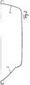
- FIG. 1 shows a deep-drawn bath 1 made of a plastic, for example sanitary acrylic, with an essentially oval bath trough 2, the rear longitudinal wall side 3 of which merges into an essentially straight rear bath rim part 4.
- the rear tub edge part 4 connects to a building wall.
- the front longitudinal wall side 5 of the tub trough and the two end faces 6 and 7 merge into an arcuate, in this case circular, front wall part 8, the ends 9, 10 of which correspond to the corresponding ends of the straight tub edge part 4 is connected.
- the tub trough 2 is arranged in such a way that the rear longitudinal wall side 3 is inclined outwards at an angle of approximately 10 °, according to the vertical, that is to say almost perpendicularly, and merges directly into the straight tub edge part 4.
- the two end faces 6 and 7 of the tub 2 which run essentially in the shape of a circular arc, merge with the major part of their upper edge into the arcuate tub edge part 8. 2, the end face 7 is inclined at an angle of approximately 60 ° with respect to the horizontal and is designed as a backrest, while the end face 7 is oriented very steeply.
- the front longitudinal wall side 5 of the tub trough 2 also extends in the apex region of the arc-shaped tub edge part 8 at a slight angle, that is to say almost perpendicularly, and merges into a flat part 11, as can be seen from the cross section in FIG. 3.
- This surface part 11 is somewhat lower than the tub edge part 8 and has a slight inclination in the direction of the tub trough 2.
- the boundary edge 12 of the surface part 11 facing the tub trough 2 is curved in the opposite direction to the tub edge part 8, so that wide entry areas 13 result in relation to the end faces 6 and 7.
- the boarding areas are easily accessible even if the bathtub directly adjoins a building wall running perpendicular to the rear bathtub edge in the area of one of its end faces.
- the surface part 11 can be provided in the region of its boundary edge 12 with an upward-pointing bead which is interrupted at the deepest point in a groove-like manner, so that a perfect drainage of water is ensured, but on the other hand there is a secure hold against slipping.
- the surface part 11 can also be profiled in its surface, For example, be corrugated or ribbed, or have an additional recessed seat recess compared to the other areas of the surface part 11.
- the end walls 6 and 7 are formed in this area in the corners formed between the straight wall part 4 and the ends 9, 10 of the arcuate tub edge part 8 in such a way that they first merge into a gusset surface 14, 15, which in turn then in merges with the tub edge in the corner area.
- the gusset surface 14 is preferably set slightly lower than the tub edge part 4, 8 in this area.
- the gusset surfaces 14, 15 can serve as storage surfaces or as a dashboard.
- a tub drain 16 is arranged centrally in the region of the side wall 3 with respect to the arch contour of the front tub edge part 8, so that there is a smooth seating possibility both with respect to the end wall 6 and the end wall 7.
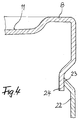
- FIG. 1 consists essentially of a profile tube space which is provided with a series of vertically extending supports which extend below the tub edge 8 and the tub edge 4 and which are each provided with adjustable adjusting elements 19 both at the upper end and at the lower end.
- the supports 18 are connected to one another via cross members 20, some of which run below and support the trough base.
- the front supports 18 are provided with fastening elements 21, on which an apron-like front wall 22, preferably releasably, is attached.
- the apron-shaped front wall 22 overlaps with its upper edge 23 the lower edge 24 of the tub edge part 8, as is shown on a larger scale in FIG. 4.
- the apron-like front wall can be in the front area, i.e. directly in their area assigned to the flat part 11, so that only this partial apron can be detached from the frame.
- a large inspection opening is thus possible if a tub designed in this way is equipped as a whirlpool tub.
- the aggregates 25 required for this, only indicated schematically, are then arranged in the space below the surface part 11 and are freely accessible from the front.
Abstract
Description
Die Erfindung betrifft eine Badewanne mit einem im Grundriss im wesentlichen ovalen Wannentrog.The invention relates to a bathtub with an essentially oval trough in plan.
Badewannen der vorstehend bezeichneten Art werden üblicherweise mit einem rechteckigen Wannenkasten aufgestellt, wobei je nach Größe des zur Verfügung stehenden Raumes die Wanne mit einer Längsseite und mit einer Stirnseite in einer Raumecke oder mit nur einer Längsseite entlang einer Gebäudewand aufgestellt wird. Will man für eine derartige Wanne, die nur längs einer Gebäudewand aufgestellt ist, also an den Stirnseiten frei zugänglich ist, ohne Verringerung des freien Trograumes zusätzliche Sitz- und/oder Ablageflächen schaffen, so ist dies nur über eine entsprechende Verbreiterung des Wannenkastens möglich. Hierdurch wäre jedoch, abgesehen von den gestalterischen Schwierigkeiten, der Einstieg in eine Wanne mit einem verbreiterten Wannenkasten nicht unwesentlich erschwert. Ein weiterer Nachteil besteht darin, daß die so gewonnene Fläche nicht als Sitzfläche verwendet werden kann, da sie außerhalb des Wannenrandes liegt und darauf abtropfendes Wasser dann in den Raum und nicht in die Badewanne abläuft.Bathtubs of the type described above are usually set up with a rectangular bathtub box, depending on the size of the available space, the bathtub is set up with a long side and with an end face in a corner of the room or with only one long side along a building wall. If you want to create additional seating and / or storage space for such a tub, which is only set up along a building wall, i.e. is freely accessible at the end faces, without reducing the free trough space, this can only be achieved by widening the tub box accordingly. Apart from the design difficulties, however, this would make the entry into a tub with a widened tub box considerably more difficult. Another disadvantage is that the surface obtained in this way cannot be used as a seat, since it is outside the tub edge and water dripping on it then runs into the room and not into the bathtub.
Der Erfindung liegt nun die Aufgabe zugrunde, eine Badewanne der eingangs bezeichneten Art zu schaffen, die bei großem Innenraum nur einen kleinen Flächenbedarf besitzt und bei entsprechender Ausgestaltung auch die Anordnung von zusätzlichen, im Bereich des Wanneninnenraums liegenden, als Sitzflächen zu benutzende Flächen ermöglicht.The invention is based on the object of creating a bathtub of the type described at the outset which, in the case of a large interior space, requires only a small amount of space and, with a corresponding design, also enables the arrangement of additional surfaces which are located in the region of the tub interior and can be used as seating surfaces.
Diese Aufgabe wird erfindungsgemäß dadurch gelöst, daß eine hintere Längswandseite des Wannentroges in einen im wesentlichen geraden hinteren Wannenrandteil übergeht und die andere Längswandseite sowie die beiden Stirnseiten des Wannentroges in einen bogenförmig verlaufenden vorderen Wandteil übergehen, der mit seinen Enden jeweils mit den Enden des geraden Wannenrandteils verbunden ist. Eine derartige Badewanne weist eine Grundfläche etwa in Form einer Halbkreisfläche auf und kann mit ihrem geraden hinteren Wannenrandteil unmittelbar an die Gebäudewand anschließend aufgestellt werden. Eine derartige Badewanne läßt sich mit sehr großem Innenraum gestalten, ohne daß der Platzbedarf über eine normale Rechteckwanne hinausgeht. Der bogenförmige Verlauf des vorderen Wannenrandteils kann hierbei in Form eines exakten Kreisbogens konstruiert sein, aber auch die Form eines Korbbogens oder eines Polygons mit abgerundeten Ecken aufweisen.This object is achieved in that a rear longitudinal wall side of the tub trough merges into a substantially straight rear tub edge part and the other longitudinal wall side and the two end faces of the tub trough merge into an arcuate front wall part, the ends of which end with the ends of the straight tub edge part connected is. Such a bathtub has a base approximately in the form of a semicircular surface and can be set up with its straight rear bathtub edge part directly on the building wall. Such a bathtub can be designed with a very large interior space without the space requirement going beyond a normal rectangular bathtub. The arcuate course of the front tub edge part can be constructed in the form of an exact circular arc, but can also have the shape of a basket arch or a polygon with rounded corners.
In einer bevorzugten Ausgestaltung der Erfindung ist vorgesehen, daß die hintere Längswandseite des Wannentroges nahezu senkrecht verläuft und unmittelbar in den geraden Wannenrandteil übergeht.In a preferred embodiment of the invention it is provided that the rear longitudinal wall side of the tub trough runs almost vertically and merges directly into the straight tub edge part.
In einer weiteren bevorzugten Ausgestaltung der Erfindung ist vorgesehen, daß die vordere Längswandseite des Wannentroges zumindest im Scheitelbereich des bogenförmigen Wannenrandteils nahezu senkrecht verläuft und in einen Flächenteil übergeht, der tiefer liegt als der Wannenrandteil und in diesen übergeht. Dies hat den Vorteil, daß der Flächenteil, der als Sitz- und/oder Ablagefläche benutzt werden kann, auf der dem Raum zugekehrten freien Längsseite des Wannentroges liegt. Da dieser Flächenteil aufgrund der geometrischen Zuordnung des im wesentlichen halbkreisförmig verlaufenden Wannenrandes einerseits und der im wesentlichen ovalen Kontur des Wannentroges andererseits verhältnismäßig groß ist, bietet dies beispielsweise behinderten Personen sowohl beim Einsteigen als auch beim Aussteigen die Möglichkeit, sich zunächst auf diesen Flächenteil zu setzen und mit sicherem Halt die Beine nacheinander über den Wannenrand zu bewegen. Da sich ein Bein immer auf dem Boden abstützt, ist auch ohne Handgriffe in den meisten Fällen ein sicherer Halt gewährleistet. Die dem Wannentrog zugekehrte Begrenzungskante des Flächenteils kann in Bezug auf den bogenförmig verlaufenden Wannenrand eine Sehne bilden oder aber in einer anderen Ausgestaltung gegenläufig zum Wannenrand gekrümmt verlaufen. Letztere Ausführungsform hat den Vorteil, daß ohne nennenswerte Reduzierung des Flächenteiles die Zugangsmöglichkeit im Bereich der Wannenstirnseite verbreitert wird, so daß auch eine Aufstellung der Badewanne mit einer hinteren Ecke unmittelbar in einer Gebäudeecke ohne Behinderung des freien Zuganges von beiden Stirnseiten her möglich ist. Ein weiterer Vorteil dieser Ausgestaltung besteht darin, daß unterhalb des Flächenteils ein zusätzlicher Raum vorhanden ist. Dieser kann beispielsweise bei einer Ausrüstung der erfindungsgemäßen Badewanne als sogenannte Whirlpool-Wanne mit Vorteil für die Unterbringung des Pumpenaggregates genutzt werden. Hier steht nicht nur ein verhältnismäßig großer Raum zur Verfügung, sondern es ist auch der Vorteil gegeben, daß dieser Raum von der Vorderseite her frei zugänglich ist.In a further preferred embodiment of the invention it is provided that the front longitudinal wall side of the tub trough runs at least almost vertically at least in the apex region of the curved tub edge part and merges into a flat part, which is lower than the tub edge part and merges into this. This has the advantage that the surface part, which can be used as a seat and / or storage surface, lies on the free long side of the tub trough facing the room. Since this area is relatively large due to the geometrical assignment of the substantially semicircular tub edge on the one hand and the substantially oval contour of the tub, on the other hand, this offers disabled people the opportunity to sit down on this area both when getting in and out to move the legs one after the other over the tub edge with a secure hold. Since one leg is always supported on the floor, a secure grip is guaranteed in most cases even without handles. The boundary edge of the surface part facing the tub trough can form a chord with respect to the arc-shaped tub rim or, in another embodiment, can be curved in the opposite direction to the tub rim. The latter embodiment has the advantage that the accessibility in the area of the tub end face is widened without any notable reduction in the area part, so that it is also possible to set up the bathtub with a rear corner directly in a building corner without obstructing free access from both end faces. Another advantage of this embodiment is that there is an additional space below the surface part. This can be used, for example, when equipping the bathtub according to the invention as a so-called whirlpool tub with advantage for accommodating the pump unit. Not only is a relatively large space available here, but there is also the advantage that this space is freely accessible from the front.
In weiterer Ausgestaltung der Erfindung ist vorgesehen, daß zumindest eine Stirnseite des Wannentroges bogenförmig verläuft und mit dem überwiegenden Teil ihres Randes in den bogenförmig verlaufenden Wannenrandteil übergeht. Hierdurch wird nicht nur eine optimale Längenausnutzung bewirkt, sondern es besteht auch hier die Möglichkeit, eine Stirnseite verhältnismäßig steil verlaufend und damit als Fußteil auszubilden und die andere Stirnseite beispielsweise unter einem Winkel von 60°, gemessen gegenüber der Horizontalen, auszurichten und als Rückenlehne auszubilden.In a further embodiment of the invention it is provided that at least one end face of the tub trough runs in an arc shape and merges with the predominant part of its edge into the arcuate trough edge part. Hereby Not only is optimal length utilization achieved, but there is also the option here of designing a relatively steep face and thus as a foot part and aligning the other face, for example at an angle of 60 °, measured relative to the horizontal, and designing it as a backrest.
In weiterer Ausgestaltung der Erfindung ist vorgesehen, daß in wenigstens einer der von dem geraden Wannenrandteil und dem bogenförmig verlaufenden Wannenrandteil gebildeten Ecken der der Ecke zugekehrte obere Randbereich der Stirnwand des Wannentroges in eine Zwickelfläche übergeht, die ihrerseits in den Wannenrandteil übergeht. Diese Zwickelflächen können durch Einformung von Mulden oder dergleichen als Ablageflächen ausgebildet oder aber auch als sogenannte Armaturenbank ausgebildet werden. Besonders zweckmäßig ist es, wenn die Zwickelfläche geringfügig tiefer liegt als der Wannenrandteil. Bei entsprechender Neigung in Richtung auf den Wannentrog ist hier ein einwandfreier Ablauf von Wasser gewährleistet.In a further embodiment of the invention it is provided that in at least one of the corners formed by the straight tub edge part and the arc-shaped tub edge part, the upper edge region of the end wall of the tub trough facing the corner merges into a gusset surface which in turn merges into the tub edge part. These gusset surfaces can be formed as storage surfaces by molding troughs or the like, or can also be designed as a so-called instrument panel. It is particularly useful if the gusset surface is slightly lower than the tub edge part. With a corresponding inclination towards the tub trough, a perfect drainage of water is guaranteed.
In weiterer Ausgestaltung der Erfindung ist vorgesehen, daß an der Außenseite zumindest an dem bogenförmig verlaufenden Wannenrandteil eine schürzenförmige Vorderwand angebracht ist. Während bei Badewannen aus Kunststoff, beispielsweise aus Sanitäracryl tiefgezogenen Badewannen, die in Wannenkästen montiert werden, die in den Raum weisende Frontfläche des Wannenkastens zusätzlich mit einer Oberflächenbeschichtung, beispielsweise mit Fliesen, versehen werden mußte, ermöglicht es die vorliegende Erfindung, hier eine schürzenförmige Vorderwand aus dem gleichen Material, beispielsweise aus Sanitäracryl, anzuschließen. Diese Vorderwand kann hierbei unmittelbar an den Wannenrand angeformt sein, so daß die Badewanne mit der in den Raum weisenden Vorderfront einheitlich aus einem Material bestehen. Hierdurch ergeben sich nicht nur besondere Gestaltungsmöglichkeiten, sondern eine derartige Wanne läßt sich auch sehr gut reinigen. Für Badewannen mit einem den Boden des Wannentroges und den Wannenrand an wenigstens einigen Stellen untergreifenden Traggestell ist in vorteilhafter Ausgestaltung der Erfindung ferner vorgesehen, daß die schürzenförmige Vorderwand am Traggestell befestigt ist und mit ihrer oberen Kante die freie Unterkante des Wannenrandes übergreift. Besonders zweckmäßig ist es, wenn zumindest ein Teilstück der Vorderwand lösbar befestigt ist. Hierdurch ergibt sich nicht nur ein einwandfreier Anschluß der Vorderwand an den Badewannenrand, sondern es besteht hier auch die Möglichkeit, bei derartigen als Whirlpool-Wannen ausgerüsteten Badewannen, einen einfachen Zugang zu der unter dem dem Raum zugekehrten Flächenteil liegenden Maschinenaggregat zu schaffen.In a further embodiment of the invention it is provided that an apron-shaped front wall is attached to the outside, at least on the arc-shaped tub edge part. While deep-drawn baths made of plastic, for example sanitary acrylic, which are installed in bath boxes, the front surface of the bath box facing the room had to be provided with a surface coating, for example with tiles, the present invention enables an apron-shaped front wall the same material, for example sanitary acrylic. This front wall can be formed directly on the tub edge, so that the tub with the front facing the room consist of one material. This not only results in special design options, but such a tub can also be cleaned very well. For bathtubs with at least the bottom of the tub and the tub edge In an advantageous embodiment of the invention, the support frame, which engages in some places, is further provided that the apron-shaped front wall is fastened to the support frame and that its upper edge engages over the free lower edge of the tub rim. It is particularly useful if at least a portion of the front wall is releasably attached. This not only results in a flawless connection of the front wall to the edge of the bathtub, but there is also the possibility, in the case of bathtubs equipped as whirlpool bathtubs, to provide easy access to the machine unit lying under the surface part facing the room.
Die Erfindung wird anhand schematischer Zeichnungen eines Ausführungsbeispieles näher erläutert. Es zeigen:
- Fig. 1
- eine Aufsicht,
- Fig. 2
- einen Längsschnitt gemäß der Linie II II in Fig. 1,
- Fig. 3
- einen Querschnitt gemäß der Linie III III in Fig. 1,
- Fig. 4
- das Detail A in Fig. 3 in größerem Maßstab.
- Fig. 1
- a supervision
- Fig. 2
- 2 shows a longitudinal section along the line II II in FIG. 1,
- Fig. 3
- 2 shows a cross section along the line III III in FIG. 1,
- Fig. 4
- the detail A in Fig. 3 on a larger scale.
In Fig. 1 ist eine aus einem Kunststoff, beispielsweise Sanitäracryl, tiefgezogene Badewanne 1 dargestellt, mit einem im wesentlichen ovalen Wannentrog 2, dessen hintere Längswandseite 3 in einen im wesentlichen geraden hinteren Wannenrandteil 4 übergeht. Der hintere Wannenrandteil 4 schließt an eine Gebäudewand an. Die vordere Längswandseite 5 des Wannentroges sowie die beiden Stirnseiten 6 und 7 gehen in einen bogenförmigen, hier kreisbogenförmig verlaufenden, vorderen Wandteil 8 über, der mit seinen Enden 9, 10 mit den entsprechenden Enden des geraden Wannenrandteils 4 verbunden ist. Der Wannentrog 2 ist hierbei so angeordnet, daß die hintere Längswandseite 3 unter einem Winkel von etwa 10°, gemssen gegenüber der Senkrechten, nach außen geneigt, also nahezu senkrecht verläuft, und unmittelbar in den geraden Wannenrandteil 4 übergeht. Die beiden im wesentlichen kreisbogenförmig verlaufenden Stirnseiten 6 und 7 des Wannentroges 2 gehen mit dem überwiegenden Teil ihres oberen Randes in den bogenförmig verlaufenden Wannenrandteil 8 über. Hierbei ist, wie im Längsschnitt gemäß Fig. 2 dargestellt, die Stirnseite 7 unter einem Winkel von etwa 60° gegenüber der Horizontalen geneigt ausgerichtet und als Rückenlehne ausgebildet, während die Stirnseite 7 sehr steil ausgerichtet ist.1 shows a deep-drawn bath 1 made of a plastic, for example sanitary acrylic, with an essentially
Die vordere Längswandseite 5 des Wannentroges 2 verläuft im Scheitelbereich des bogenförmigen Wannenrandteils 8 ebenfalls unter einem geringen Winkel nach außen geneigt, also nahezu senkrecht, und geht in einen Flächenteil 11 über, wie dies aus dem Querschnitt in Fig. 3 ersichtlich ist. Dieser Flächenteil 11 liegt etwas tiefer als der Wannenrandteil 8 und weist eine geringe Neigung in Richtung auf den Wannentrog 2 auf.The front
Wie die Aufsicht gemäß Fig. 1 erkennen läßt, ist die dem Wannentrog 2 zugekehrte Begrenzungskante 12 des Flächenteils 11 gegenläufig zum Wannenrandteil 8 gekrümmt, so daß sich in Bezug auf die Stirnseiten 6 und 7 breite Einstiegsbereiche 13 ergeben. Die Einstiegsbereiche sind selbst dann bequem zugänglich, wenn die Badewanne im Bereich einer ihrer Stirnseiten an eine senkrecht zum hinteren Wannenrandteil verlaufende Gebäudewand unmittelbar anschließt. Der Flächenteil 11 kann hierbei im Bereich seiner Begrenzungskante 12 mit einem nach oben weisenden Wulst versehen sein, der an der tiefsten Stelle rinnenartig unterbrochen ist, so daß ein einwandfreier Wasserablauf gewährleistet ist, andererseits jedoch ein sicherer Halt gegen Abrutschen gegeben ist. Der Flächenteil 11 kann auch in seiner Oberfläche profiliert, beispielsweise gewellt oder gerippt sein, oder eine zusätzliche, gegenüber den übrigen Bereichen des Flächenteils 11 noch vertiefte Sitzmulde aufweisen.As can be seen from the top view according to FIG. 1, the
In den zwischen dem geraden Wandteil 4 und den Enden 9, 10 des bogenförmigen Wannenrandteils 8 gebildeten Ecken sind bei dem dargestellten Ausführungsbeispiel die Stirnwände 6 und 7 in diesem Bereich so ausgebildet, daß sie zunächst in eine Zwickelfläche 14, 15 übergehen, die ihrerseits dann in den Wannenrand im Eckenbereich übergeht. Bevorzugt ist die Zwickelfläche 14 geringfügig tiefer gelegt als der Wannenrandteil 4, 8 in diesem Bereich. Die Zwickelflächen 14, 15 können hierbei als Ablageflächen oder aber auch als Armaturenbank dienen.In the illustrated embodiment, the
Bei dem dargestellten Ausführungsbeispiel ist ein Wannenablauf 16 im Bereich der Seitenwand 3 in Bezug auf die Bogenkontur des vorderen Wannenrandteils 8 mittig angeordnet, so daß eine glatte Sitzmöglichkeit sowohl in Bezug auf die Stirnwand 6 als auch auf die Stirnwand 7 gegeben ist.In the illustrated embodiment, a
Während es grundsätzlich möglich ist, auch eine derartige Wanne mit Hilfe eines sogenannten Wannenkastens zu montieren, bei dem bis unter den Wannenrandteil 8 reichende Wandelemente aus einem Hartschaum fest miteinander verbunden werden und die Wanne randseitig unterstützen, während der Boden mit Hilfe von Wannenfüßen abgestützt wird, ist in Fig. 3 die Befestigung mit Hilfe eines Wannengestells 17 angedeutet. Dies besteht im wesentlichen aus einem Profilrohrraum, der mit einer Reihe von vertikal verlaufenden Stützen versehen ist, die bis unter den Wannenrand 8 und den Wannenrand 4 reichen und die sowohl am oberen Ende als auch am unteren Ende jeweils mit einstellbaren Justierelementen 19 versehen sind. Die Stützen 18 sind hierbei über Querträger 20 miteinander verbunden, von denen einige unterhalb des Wannenbodens verlaufen und diesen abstützen. Die frontseitigen Stützen 18 sind hierbei mit Befestigungselementen 21 versehen, an denen eine schürzenartige Vorderwand 22, vorzugsweise lösbar, befestigt ist. Die schürzenförmige Vorderwand 22 übergreift mit ihrer oberen Kante 23 die Unterkante 24 des Wannenrandteils 8, wie dies in Fig. 4 in größerem Maßstab dargestellt ist.While it is fundamentally possible to also mount such a tub with the help of a so-called tub box, in which wall elements reaching from below the
Die schürzenartige Vorderwand kann hierbei im Frontbereich, d.h. unmittelbar in ihrem dem Flächteil 11 zugeordneten Bereich, geteilt sein, so daß nur diese Teilschürze vom Gestell lösbar ist. Damit ist eine große Revisionsöffnung möglich, wenn eine derartig ausgebildete Wanne als Whirlpool-Wanne ausgerüstet ist. Die hierzu erforderlichen, nur schematisch angedeuteten Aggregate 25 sind dann in dem Raum unterhalb des Flächenteils 11 angeordnet und frei von vorne zugänglich.The apron-like front wall can be in the front area, i.e. directly in their area assigned to the
Claims (12)
daß eine hintere Längswandseite (3) des Wannentroges (2) in einen im wesentlichen geraden hinteren Wannenrandteil (4) übergeht und die andere Längswandseite (5) sowie die beiden Stirnseiten (6, 7) des Wannentroges (2) in einen bogenförmig verlaufenden vorderen Wannenrandteil (8) übergehen, der mit seinen Enden (9, 10) jeweils mit den Enden des geraden Wannenrandteils (4) verbunden ist.Bathtub, with an essentially oval trough in the floor plan, characterized in that
that a rear longitudinal wall side (3) of the tub trough (2) merges into a substantially straight rear tub edge part (4) and the other longitudinal wall side (5) and the two end faces (6, 7) of the tub trough (2) in an arcuate front tub edge part (8) pass, which is connected with its ends (9, 10) to the ends of the straight tub edge part (4).
Applications Claiming Priority (2)
| Application Number | Priority Date | Filing Date | Title |
|---|---|---|---|
| DE4025940A DE4025940A1 (en) | 1990-08-16 | 1990-08-16 | BATHTUB |
| DE4025940 | 1990-08-16 |
Publications (3)
| Publication Number | Publication Date |
|---|---|
| EP0472884A2 true EP0472884A2 (en) | 1992-03-04 |
| EP0472884A3 EP0472884A3 (en) | 1992-09-16 |
| EP0472884B1 EP0472884B1 (en) | 1995-10-18 |
Family
ID=6412348
Family Applications (1)
| Application Number | Title | Priority Date | Filing Date |
|---|---|---|---|
| EP91111903A Expired - Lifetime EP0472884B1 (en) | 1990-08-16 | 1991-07-17 | Bathtub |
Country Status (3)
| Country | Link |
|---|---|
| EP (1) | EP0472884B1 (en) |
| AT (1) | ATE129135T1 (en) |
| DE (3) | DE4042679C2 (en) |
Cited By (3)
| Publication number | Priority date | Publication date | Assignee | Title |
|---|---|---|---|---|
| EP0564978A1 (en) * | 1992-04-07 | 1993-10-13 | HOESCH Metall + Kunststoffwerk GmbH & Co. | Trapezoidal bathtub |
| FR2690829A1 (en) * | 1992-05-08 | 1993-11-12 | Dueker Eisenwerk | Pump driven bubbling bath for washing - includes pump and control system mounted beneath bath, inside panelling to allow access |
| EP2153764A3 (en) * | 2008-08-15 | 2012-01-04 | Masco Bath Corporation | Bath system |
Families Citing this family (1)
| Publication number | Priority date | Publication date | Assignee | Title |
|---|---|---|---|---|
| DE19520273C2 (en) * | 1995-06-02 | 2000-10-26 | A & S Baeder Gmbh | bathtub |
Citations (7)
| Publication number | Priority date | Publication date | Assignee | Title |
|---|---|---|---|---|
| FR342751A (en) * | 1904-04-30 | 1904-09-16 | Bono Et Cie Soc | Bathtub equipped for showers |
| GB962141A (en) * | 1962-01-03 | 1964-07-01 | Henry Carlyle Wilson Bennetts | Baths |
| US3257669A (en) * | 1963-07-08 | 1966-06-28 | Allyn C Fay | Bath tub fitted with removable panel, center drain and wall sealing means |
| DE1921004A1 (en) * | 1969-04-24 | 1970-11-05 | Walter Thiele | Foot bath |
| DE3229451A1 (en) * | 1982-08-06 | 1984-02-09 | Reinhard 8939 Rammingen Nieberle | Bath tub |
| DE8900394U1 (en) * | 1989-01-14 | 1989-03-02 | Pauli, Willi | |
| DE8901533U1 (en) * | 1989-02-10 | 1989-04-20 | Oespag Oesterreichische Sanitaer-, Keramik- Und Porzellan-Industrie Ag, Wien, At |
-
1990
- 1990-08-16 DE DE4042679A patent/DE4042679C2/en not_active Expired - Fee Related
- 1990-08-16 DE DE4025940A patent/DE4025940A1/en not_active Withdrawn
-
1991
- 1991-07-17 EP EP91111903A patent/EP0472884B1/en not_active Expired - Lifetime
- 1991-07-17 AT AT91111903T patent/ATE129135T1/en not_active IP Right Cessation
- 1991-07-17 DE DE59106713T patent/DE59106713D1/en not_active Expired - Fee Related
Patent Citations (7)
| Publication number | Priority date | Publication date | Assignee | Title |
|---|---|---|---|---|
| FR342751A (en) * | 1904-04-30 | 1904-09-16 | Bono Et Cie Soc | Bathtub equipped for showers |
| GB962141A (en) * | 1962-01-03 | 1964-07-01 | Henry Carlyle Wilson Bennetts | Baths |
| US3257669A (en) * | 1963-07-08 | 1966-06-28 | Allyn C Fay | Bath tub fitted with removable panel, center drain and wall sealing means |
| DE1921004A1 (en) * | 1969-04-24 | 1970-11-05 | Walter Thiele | Foot bath |
| DE3229451A1 (en) * | 1982-08-06 | 1984-02-09 | Reinhard 8939 Rammingen Nieberle | Bath tub |
| DE8900394U1 (en) * | 1989-01-14 | 1989-03-02 | Pauli, Willi | |
| DE8901533U1 (en) * | 1989-02-10 | 1989-04-20 | Oespag Oesterreichische Sanitaer-, Keramik- Und Porzellan-Industrie Ag, Wien, At |
Cited By (4)
| Publication number | Priority date | Publication date | Assignee | Title |
|---|---|---|---|---|
| EP0564978A1 (en) * | 1992-04-07 | 1993-10-13 | HOESCH Metall + Kunststoffwerk GmbH & Co. | Trapezoidal bathtub |
| FR2690829A1 (en) * | 1992-05-08 | 1993-11-12 | Dueker Eisenwerk | Pump driven bubbling bath for washing - includes pump and control system mounted beneath bath, inside panelling to allow access |
| BE1007923A3 (en) * | 1992-05-08 | 1995-11-21 | Dueker Eisenwerk | BATH bubbling. |
| EP2153764A3 (en) * | 2008-08-15 | 2012-01-04 | Masco Bath Corporation | Bath system |
Also Published As
| Publication number | Publication date |
|---|---|
| EP0472884A3 (en) | 1992-09-16 |
| DE4042679C2 (en) | 2003-07-17 |
| DE59106713D1 (en) | 1995-11-23 |
| EP0472884B1 (en) | 1995-10-18 |
| DE4025940A1 (en) | 1992-02-20 |
| ATE129135T1 (en) | 1995-11-15 |
Similar Documents
| Publication | Publication Date | Title |
|---|---|---|
| DE2855993C3 (en) | coffin | |
| CH675197A5 (en) | ||
| EP0472884B1 (en) | Bathtub | |
| DE2831929A1 (en) | ARRANGEMENT OF BATHTUBS | |
| DE19606542C2 (en) | Frame made of aluminum profiles for gates | |
| DE2911359C2 (en) | ||
| DE3047509C2 (en) | Shower tray with a square installation cross-section | |
| CH667793A5 (en) | BATHTUB WITH ARMREST. | |
| EP0532827B1 (en) | Shower cabinet | |
| EP0460410B1 (en) | Bathtub with footrests | |
| DE19603408A1 (en) | Spacious vehicle for the transportation of people, especially low-floor light rail vehicles | |
| EP0386276B1 (en) | Shower partition | |
| DE3707965C2 (en) | ||
| DE60010760T3 (en) | Shower cabin and seal arrangement | |
| DE6930002U (en) | BATHTUB | |
| DE2828031C3 (en) | Partition wall for a shower or bathtub partition | |
| EP0344588A1 (en) | Shower cubicle | |
| DE19801044C2 (en) | Cladding system for a bathtub, preferably a bathtub | |
| DE19917712C2 (en) | Badkonstruktion | |
| DE3334481A1 (en) | Height-adjustable washbasin | |
| DE2518823C2 (en) | Grab bar for bathroom | |
| AT410646B (en) | DEVICE FOR PRODUCING CONCRETE PARTS | |
| AT391996B (en) | CORNER SHOWER TRAY | |
| DE7403089U (en) | bathtub | |
| DE2854176A1 (en) | UPPER FRAME PROFILE OF A SHOWER PARTITION |
Legal Events
| Date | Code | Title | Description |
|---|---|---|---|
| PUAI | Public reference made under article 153(3) epc to a published international application that has entered the european phase |
Free format text: ORIGINAL CODE: 0009012 |
|
| AK | Designated contracting states |
Kind code of ref document: A2 Designated state(s): AT BE CH DE DK ES FR GB GR IT LI LU NL SE |
|
| PUAL | Search report despatched |
Free format text: ORIGINAL CODE: 0009013 |
|
| AK | Designated contracting states |
Kind code of ref document: A3 Designated state(s): AT BE CH DE DK ES FR GB GR IT LI LU NL SE |
|
| 17P | Request for examination filed |
Effective date: 19920922 |
|
| 17Q | First examination report despatched |
Effective date: 19931220 |
|
| GRAA | (expected) grant |
Free format text: ORIGINAL CODE: 0009210 |
|
| AK | Designated contracting states |
Kind code of ref document: B1 Designated state(s): AT BE CH DE DK ES FR GB GR IT LI LU NL SE |
|
| PG25 | Lapsed in a contracting state [announced via postgrant information from national office to epo] |
Ref country code: GR Free format text: LAPSE BECAUSE OF FAILURE TO SUBMIT A TRANSLATION OF THE DESCRIPTION OR TO PAY THE FEE WITHIN THE PRESCRIBED TIME-LIMIT Effective date: 19951018 Ref country code: GB Effective date: 19951018 Ref country code: ES Free format text: THE PATENT HAS BEEN ANNULLED BY A DECISION OF A NATIONAL AUTHORITY Effective date: 19951018 Ref country code: DK Effective date: 19951018 |
|
| REF | Corresponds to: |
Ref document number: 129135 Country of ref document: AT Date of ref document: 19951115 Kind code of ref document: T |
|
| REF | Corresponds to: |
Ref document number: 59106713 Country of ref document: DE Date of ref document: 19951123 |
|
| ITF | It: translation for a ep patent filed |
Owner name: BARZANO' E ZANARDO ROMA S.P.A. |
|
| PG25 | Lapsed in a contracting state [announced via postgrant information from national office to epo] |
Ref country code: SE Effective date: 19960118 |
|
| REG | Reference to a national code |
Ref country code: CH Ref legal event code: NV Representative=s name: BOVARD AG PATENTANWAELTE |
|
| ET | Fr: translation filed | ||
| GBV | Gb: ep patent (uk) treated as always having been void in accordance with gb section 77(7)/1977 [no translation filed] |
Effective date: 19951018 |
|
| PG25 | Lapsed in a contracting state [announced via postgrant information from national office to epo] |
Ref country code: LU Free format text: LAPSE BECAUSE OF NON-PAYMENT OF DUE FEES Effective date: 19960731 Ref country code: LI Effective date: 19960731 Ref country code: CH Effective date: 19960731 Ref country code: BE Effective date: 19960731 |
|
| PLBE | No opposition filed within time limit |
Free format text: ORIGINAL CODE: 0009261 |
|
| STAA | Information on the status of an ep patent application or granted ep patent |
Free format text: STATUS: NO OPPOSITION FILED WITHIN TIME LIMIT |
|
| 26N | No opposition filed | ||
| BERE | Be: lapsed |
Owner name: HOESCH METALL + KUNSTSTOFFWERK G.M.B.H. & CO. Effective date: 19960731 |
|
| REG | Reference to a national code |
Ref country code: CH Ref legal event code: PL |
|
| PGFP | Annual fee paid to national office [announced via postgrant information from national office to epo] |
Ref country code: AT Payment date: 19970730 Year of fee payment: 7 |
|
| PG25 | Lapsed in a contracting state [announced via postgrant information from national office to epo] |
Ref country code: AT Free format text: LAPSE BECAUSE OF NON-PAYMENT OF DUE FEES Effective date: 19980717 |
|
| PGFP | Annual fee paid to national office [announced via postgrant information from national office to epo] |
Ref country code: NL Payment date: 19980731 Year of fee payment: 8 Ref country code: FR Payment date: 19980731 Year of fee payment: 8 |
|
| PG25 | Lapsed in a contracting state [announced via postgrant information from national office to epo] |
Ref country code: FR Free format text: THE PATENT HAS BEEN ANNULLED BY A DECISION OF A NATIONAL AUTHORITY Effective date: 19990731 |
|
| PG25 | Lapsed in a contracting state [announced via postgrant information from national office to epo] |
Ref country code: NL Free format text: LAPSE BECAUSE OF NON-PAYMENT OF DUE FEES Effective date: 20000201 |
|
| NLV4 | Nl: lapsed or anulled due to non-payment of the annual fee |
Effective date: 20000201 |
|
| REG | Reference to a national code |
Ref country code: FR Ref legal event code: ST |
|
| PGFP | Annual fee paid to national office [announced via postgrant information from national office to epo] |
Ref country code: DE Payment date: 20020717 Year of fee payment: 12 |
|
| PG25 | Lapsed in a contracting state [announced via postgrant information from national office to epo] |
Ref country code: DE Free format text: LAPSE BECAUSE OF NON-PAYMENT OF DUE FEES Effective date: 20040203 |
|
| PG25 | Lapsed in a contracting state [announced via postgrant information from national office to epo] |
Ref country code: IT Free format text: LAPSE BECAUSE OF NON-PAYMENT OF DUE FEES Effective date: 20050717 |