EP0472233A2 - Zweigangnachschaltgetriebe - Google Patents
Zweigangnachschaltgetriebe Download PDFInfo
- Publication number
- EP0472233A2 EP0472233A2 EP91201996A EP91201996A EP0472233A2 EP 0472233 A2 EP0472233 A2 EP 0472233A2 EP 91201996 A EP91201996 A EP 91201996A EP 91201996 A EP91201996 A EP 91201996A EP 0472233 A2 EP0472233 A2 EP 0472233A2
- Authority
- EP
- European Patent Office
- Prior art keywords
- final drive
- selectively
- gear
- transmission
- stage final
- Prior art date
- Legal status (The legal status is an assumption and is not a legal conclusion. Google has not performed a legal analysis and makes no representation as to the accuracy of the status listed.)
- Granted
Links
Images

Classifications
-
- F—MECHANICAL ENGINEERING; LIGHTING; HEATING; WEAPONS; BLASTING
- F16—ENGINEERING ELEMENTS AND UNITS; GENERAL MEASURES FOR PRODUCING AND MAINTAINING EFFECTIVE FUNCTIONING OF MACHINES OR INSTALLATIONS; THERMAL INSULATION IN GENERAL
- F16H—GEARING
- F16H48/00—Differential gearings
- F16H48/06—Differential gearings with gears having orbital motion
- F16H48/08—Differential gearings with gears having orbital motion comprising bevel gears
-
- B—PERFORMING OPERATIONS; TRANSPORTING
- B60—VEHICLES IN GENERAL
- B60K—ARRANGEMENT OR MOUNTING OF PROPULSION UNITS OR OF TRANSMISSIONS IN VEHICLES; ARRANGEMENT OR MOUNTING OF PLURAL DIVERSE PRIME-MOVERS IN VEHICLES; AUXILIARY DRIVES FOR VEHICLES; INSTRUMENTATION OR DASHBOARDS FOR VEHICLES; ARRANGEMENTS IN CONNECTION WITH COOLING, AIR INTAKE, GAS EXHAUST OR FUEL SUPPLY OF PROPULSION UNITS IN VEHICLES
- B60K17/00—Arrangement or mounting of transmissions in vehicles
- B60K17/04—Arrangement or mounting of transmissions in vehicles characterised by arrangement, location or kind of gearing
- B60K17/06—Arrangement or mounting of transmissions in vehicles characterised by arrangement, location or kind of gearing of change-speed gearing
- B60K17/08—Arrangement or mounting of transmissions in vehicles characterised by arrangement, location or kind of gearing of change-speed gearing of mechanical type
-
- F—MECHANICAL ENGINEERING; LIGHTING; HEATING; WEAPONS; BLASTING
- F16—ENGINEERING ELEMENTS AND UNITS; GENERAL MEASURES FOR PRODUCING AND MAINTAINING EFFECTIVE FUNCTIONING OF MACHINES OR INSTALLATIONS; THERMAL INSULATION IN GENERAL
- F16D—COUPLINGS FOR TRANSMITTING ROTATION; CLUTCHES; BRAKES
- F16D41/00—Freewheels or freewheel clutches
- F16D41/06—Freewheels or freewheel clutches with intermediate wedging coupling members between an inner and an outer surface
- F16D41/08—Freewheels or freewheel clutches with intermediate wedging coupling members between an inner and an outer surface with provision for altering the freewheeling action
- F16D41/086—Freewheels or freewheel clutches with intermediate wedging coupling members between an inner and an outer surface with provision for altering the freewheeling action the intermediate members being of circular cross-section and wedging by rolling
- F16D41/088—Freewheels or freewheel clutches with intermediate wedging coupling members between an inner and an outer surface with provision for altering the freewheeling action the intermediate members being of circular cross-section and wedging by rolling the intermediate members being of only one size and wedging by a movement not having an axial component, between inner and outer races, one of which is cylindrical
-
- F—MECHANICAL ENGINEERING; LIGHTING; HEATING; WEAPONS; BLASTING
- F16—ENGINEERING ELEMENTS AND UNITS; GENERAL MEASURES FOR PRODUCING AND MAINTAINING EFFECTIVE FUNCTIONING OF MACHINES OR INSTALLATIONS; THERMAL INSULATION IN GENERAL
- F16H—GEARING
- F16H3/00—Toothed gearings for conveying rotary motion with variable gear ratio or for reversing rotary motion
- F16H3/44—Toothed gearings for conveying rotary motion with variable gear ratio or for reversing rotary motion using gears having orbital motion
- F16H3/62—Gearings having three or more central gears
-
- F—MECHANICAL ENGINEERING; LIGHTING; HEATING; WEAPONS; BLASTING
- F16—ENGINEERING ELEMENTS AND UNITS; GENERAL MEASURES FOR PRODUCING AND MAINTAINING EFFECTIVE FUNCTIONING OF MACHINES OR INSTALLATIONS; THERMAL INSULATION IN GENERAL
- F16H—GEARING
- F16H37/00—Combinations of mechanical gearings, not provided for in groups F16H1/00 - F16H35/00
- F16H37/02—Combinations of mechanical gearings, not provided for in groups F16H1/00 - F16H35/00 comprising essentially only toothed or friction gearings
- F16H37/04—Combinations of toothed gearings only
- F16H37/042—Combinations of toothed gearings only change gear transmissions in group arrangement
- F16H37/046—Combinations of toothed gearings only change gear transmissions in group arrangement with an additional planetary gear train, e.g. creep gear, overdrive
Definitions
- This invention relates to final drive arrangements for a power transmission, and more particularly, to such final drive arrangements wherein two speed ratios are provided within the final drive.
- US-A-4,412,459 describes an arrangement in accordance with the preamble of claim 1 and provides a planetary gear set which is a single ratio assembly.
- a two-stage final drive in accordance with the present invention is characterised over US-A-4,142,459 by the features specified in the characterising portion of claim 1.
- the present invention provides a two-stage final drive arrangement which can be incorporated into many existing vehicle powertrains between the transmission output and the differential gear unit input.
- two underdrive gear ratios are provided through the use of a stepped pinion planetary gear arrangement having a sun gear input, two ring gear reaction elements and a carrier output.
- the ring gear which provides reaction for the lowest of the two-speed ratios is controlled by both a roller brake and a selectively engageable friction brake.
- the friction brake will, of course, provide reaction force independent of the direction of rotation.
- the roller brake in the preferred embodiment has a selectively operable control element which permits the roller brake to be operable independently of the direction of rotation of the reaction member.
- the roller brake can provide a reaction member whenever the transmission is conditioned for Park, Reverse, Neutral or forward drive operation.
- the roller brake must permit overrunning during the selection of the higher ratio. This is accomplished by providing control springs disposed to abut each roller thereby preventing the normal camming action associated with one-way roller devices. To permit or enforce the camming action in both directions of rotation, the control spring is manipulated to a position wherein the outer surface of the roller is abutted tangentially by the spring at the point of contact with the cam surface, thereby limiting the circumferential movement of the rollers relative to the cam surface.
- the conventional park brake mechanism can be utilized in the transmission such that engagement between a brake pawl in the final drive differential carrier is not required.
- the use of a two-stage final drive will benefit a three or four speed automatic transmission by increasing the ratio coverage without requiring a design change of the gear ratios and elements found in the three or four speed transmission.
- the added ratio coverage permits the transmission to be utilized with existing engines and transmission combinations with a wider variety of vehicles.
- the present invention preferably provides an improved final drive arrangement disposed between a transmission output member and a differential input member, wherein a planetary gear arrangement incorporates an input sun gear and two selectively operable reaction ring gears to establish two underdrive ratios, and further wherein, one of the ring gear members has operatively connected therewith a selectively controllable roller brake mechanism for providing two-way braking whenever the transmission output is in a Low or Reverse operating mode and an overrun condition when the other reaction ring gear of the final drive arrangement is selectively retarded to provide a high speed ratio.
- the present invention may also provide an improved two-stage final drive arrangement, as described above, wherein the selectively operable roller brake mechanism will establish a reaction member within the two-stage final drive arrangement whenever the transmission is conditioned for Park, Reverse, Neutral or Low gear operation.
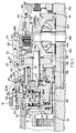
- FIG. 1 a two-stage final drive or planetary arrangement 10 disposed between a transmission output member 12 and a differential gear assembly 14.
- the transmission output member 12 is a component in a conventional three speed automatic transmission, such as that shown in US-A-4,223,569.
- the transmission includes a housing or casing 16 in which the transmission components, not shown, are enclosed and a transmission output shaft 18 which is drivingly connected with the transmission output member 12.
- the transmission output member 12 has a conventional park gear 20 formed on the outer surface thereof which is selectively engaged in a well-known manner by a conventional parking pawl, not shown.
- An extension housing 22 is secured to the transmission housing 16 and also to an end cover or differential housing 24.
- the two-stage final drive 10 is disposed mainly within the extension housing 22 and includes a sun gear 26, a pair of ring gears 28 and 30, and a planet carrier assembly 32.
- the planet carrier assembly 32 is comprised of a plurality of stepped pinions 34, each of which is rotatably journalled on a pinion pin 36 secured in a pair of planet carrier side plates 38 and 40.
- the sun gear 26 is drivingly connected to the transmission output shaft 18 for continuous rotation therewith thereby establishing an input member for the two-stage final drive 10.
- the ring gear 28 has an outer drum surface 42 which is encircled by a conventional double wrap band 44.
- the ring gear 28 also has a hub portion 46 which is rotatably supported on a support member 48, which in turn is secured to the extension housing 22 through an outer race 50 of a roller brake 52.
- the outer race 50 is splined to the extension housing 22 at 54 so as to be rotatably fixed thereto.
- the hub portion 46 of the ring gear 28 also provides an inner race 56 for the roller brake 52.
- a plurality of rollers 58 are disposed between the inner race 56 and outer race 50.
- the inner race 56 has a smooth cylindrical surface 60 in contact with the rollers 58 and the outer race 50 has a cam surface 62 disposed in contact with the rollers 58.
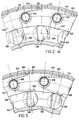
- a plurality of finger springs or torsion springs 64 and 66 are rotatably journalled on support posts 68 and 70, respectively, which in turn are secured to retainer plates 72 and 74.
- the retainer plates 72 and 74 are interconnected by a plurality of bridging plates 76, which pass through openings 78 formed in the outer surface of the outer race 50.
- Each spring 64 and 66 has an extension, such as 80, shown in Figures 2 and 3, which abut a wall 82 formed in the retainer plate 72, or a wall 84 formed in the retainer plate 74.
- the retainer plate 74 has a drive plate 86 secured thereto and extending radially outward from the outer race 50.
- the drive plate 86 is retained in a notch 88 formed in a control piston 90 which is slidably disposed in a cylinder 92 formed in the extension housing 22.
- the control piston 90 is urged upward, as viewed in Figure 4, by a spring 94 and downward to the position shown by fluid pressure selectively admitted in a conventional manner through passage 96 to the cylinder 92.
- the retainer plates 72 and 74 are positioned to provide the spring position, shown in Figure 2, wherein a control finger 98 of each finger spring 64, 66 is positioned to prevent the rollers 58 from causing braking operation between the inner and outer races 56, 50 when the inner race is rotated in the clockwise direction when viewed in Figure 2.
- the rollers 58 will engage in the cam surface 62, such that the inner race 56 will be held stationary. This corresponds to forward rotation of the ring gear 28.
- Forward rotation of the ring gear 28 will occur whenever the transmission output shaft 18 and therefore sun gear 26 are rotated in the reverse direction.
- Forward and reverse rotational directions refer to the direction of vehicle travel as determined by the gear ratio selected in the transmission.
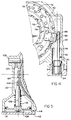
- the ring gear 28 also has associated therewith the double wrap brake band 44 which, as seen in Figure 5, has one end 100 grounded by a reaction pin 102 secured in the extension housing 22 and the other end 104 selectively controlled by a piston rod 106 which is driven by a pressure operated piston 108 slidably disposed in a cylinder 110 formed in the housing 22.
- a cap member 112 seals the cylinder 110 from atmosphere, such that fluid pressure can be admitted through a passage 114 to cause the piston 108 to move upwardly against a return spring 116 to enforce contraction of the brake band 44 on to the outer drum surface 42, thereby preventing rotation of the ring gear 28.
- the ring gear 28 can be controlled or connected to ground by either the double acting roller brake 52 or the brake band 44. It is also obvious that the roller brake 52 can be selectively controlled to permit the one-way operation, thus permitting free wheeling of the ring gear 28 when the sun gear 26 is rotated in the forward direction by the transmission output shaft 18.
- the planet carrier assembly 32 When the ring gear 28 is held stationary and the sun gear 26 is rotated in either the forward or reverse direction, the planet carrier assembly 32 will rotate in the same direction as the sun gear 26, but at a reduced speed determined by the number of teeth on the sun gear 26 and the ring gear 28.
- the ring gear 30 meshes with a large diameter gear portion 118 of the stepped pinions 34.
- a hub 120 is secured to the ring gear 30 and rotatably supported by a support member 122 secured in the differential housing 24.
- the hub 120 has formed thereon a spline portion 124 which engages a plurality of friction plates 126 which are components within a disc brake 128.
- a plurality of friction discs 130 and a back plate 132 are splined to the differential housing 24 and also are components of the disc brake 128.
- the disc brake 128 has a pressure operated engaging piston 134 which is slidably disposed in the differential housing 24 and selectively operated in a conventional manner by fluid pressure introduced in a cylinder or chamber 136.
- the engaging piston 134 When fluid pressure is introduced in the chamber 136, the engaging piston 134 will move leftward, as viewed in Figure 1, to cause frictional engagement between the friction plates 126 and friction discs 130 to provide securement of the ring gear 30 with the differential housing 24.
- a plurality of return springs 138 are provided which will ensure rightward movement of the engaging piston 134 when the fluid pressure in chamber 136 is relieved.
- the planet carrier assembly 32 When the disc brake 128 is engaged and the ring gear 30 is held stationary, the planet carrier assembly 32 will rotate in the same direction as the sun gear 26 but at a reduced speed.
- the speed of the planet carrier assembly 32 will depend upon the number of teeth on the sun gear 26 and the ring gear 30. Since the ring gear 30 is larger than the ring gear 28, the speed of the planet carrier assembly 32 will be greater when the ring gear 30 is restrained as compared to the restraining of ring gear 28 at any given input speed of the sun gear 26.
- the ring gear 30 is a high speed reaction member and the ring gear 28 is a low speed reaction member.
- the carrier side plate 38 is formed integral with or otherwise secured to a differential carrier 140, which is a component in the differential gear assembly 14.
- the differential carrier 140 rotates in unison with the planet carrier assembly 32 and thus will be driven either forwardly or reversely. The direction of rotation will depend on the gear selection in the main transmission.
- the output will rotate at a speed relative to the speed of transmission output member 12, depending upon which of the ring gears 28 or 30 is held stationary.
- the differential gear assembly 14 also includes a pair of side gears 142 and 144 and a pair of pinion gears 146.
- the pinion gears 146 are rotatably supported on the pins 148 which are secured in the differential carrier 140.
- the side gears 142 and 144 are connected with respective differential output shafts 150 and 152, which in turn, are connected in a conventional manner to the drive wheels of the vehicle.
- a chart shown in Figure 6 describes the operation of the two-stage final drive when combined with a three-speed transmission.
- the roller brake 52 is in a bidirectional mode in Park and Reverse, and is always in the overrunning mode to provide the fourth or highest speed ratio. The higher speed ratio is provided when the main transmission has achieved its highest speed ratio with the two-speed planetary then being shifted from the low to the high ratio.
- roller brake 52 acting as a two-way brake is important during the manipulation of the main transmission to the Park setting.
- the transmission output member 12 In the Park setting, the transmission output member 12 is held stationary. However, the vehicle will not be held stationary unless there is a ground member formed in the two-stage final drive 10. If the roller brake 52 were only a one-way device, the vehicle would be free to roll in the forward direction during Park. However, since the roller brake 52 is conditioned, as shown in Figure 3, during the Park setting, the ring gear 28 will provide a reaction and therefore prevent inadvertent movement of the vehicle.
- Figures 7 and 8 provide an alternative embodiment, wherein the roller brake 52' is a one-way device and therefore will restrain the ring gear 28' from rotation in only one direction.
- a disc brake 160 is provided to control the positive grounding of the ring gear 28'.
- a secondary mechanical braking arrangement 161 is provided for the ring gear 28'.
- This mechanical braking arrangement 161 includes a gear 162 which is formed on the output surface of the ring gear 28', and a pawl 164 which is pivotally disposed in the extension housing 22 on a pin 166 and urged into engagement with the gear 162 by a spring 168.
- a selectively controllable fluid operated piston 170 is provided to control pivoting of the pawl 164 about the pin 166 to enforce disengagement between the pawl 164 and the gear 162.
- the gear 162 is configured such that during engagement with the pawl 164, rotation in the clockwise direction is restricted while rotation in the counterclockwise direction is permitted due to the angular shape of the pawl 164 engaged with the gear 162.
Landscapes
- Engineering & Computer Science (AREA)
- General Engineering & Computer Science (AREA)
- Mechanical Engineering (AREA)
- Chemical & Material Sciences (AREA)
- Combustion & Propulsion (AREA)
- Transportation (AREA)
- Structure Of Transmissions (AREA)
Applications Claiming Priority (2)
| Application Number | Priority Date | Filing Date | Title |
|---|---|---|---|
| US07/571,813 US5046997A (en) | 1990-08-24 | 1990-08-24 | Two-stage final drive |
| US571813 | 2000-05-16 |
Publications (3)
| Publication Number | Publication Date |
|---|---|
| EP0472233A2 true EP0472233A2 (de) | 1992-02-26 |
| EP0472233A3 EP0472233A3 (en) | 1992-04-22 |
| EP0472233B1 EP0472233B1 (de) | 1995-01-25 |
Family
ID=24285176
Family Applications (1)
| Application Number | Title | Priority Date | Filing Date |
|---|---|---|---|
| EP91201996A Expired - Lifetime EP0472233B1 (de) | 1990-08-24 | 1991-08-01 | Zweigangnachschaltgetriebe |
Country Status (3)
| Country | Link |
|---|---|
| US (1) | US5046997A (de) |
| EP (1) | EP0472233B1 (de) |
| DE (1) | DE69106980T2 (de) |
Cited By (3)
| Publication number | Priority date | Publication date | Assignee | Title |
|---|---|---|---|---|
| RU2353836C2 (ru) * | 2007-03-27 | 2009-04-27 | Борис Васильевич Пылаев | Реверсивная зубчатая обгонная муфта |
| DE102016201225A1 (de) * | 2016-01-28 | 2017-01-26 | Schaeffler Technologies AG & Co. KG | Planetengetriebe für ein Kraftfahrzeug |
| DE102016201223A1 (de) * | 2016-01-28 | 2017-03-09 | Schaeffler Technologies AG & Co. KG | Planetengetriebe für ein Kraftfahrzeug |
Families Citing this family (6)
| Publication number | Priority date | Publication date | Assignee | Title |
|---|---|---|---|---|
| US5397282A (en) * | 1993-09-07 | 1995-03-14 | Weidman; William A. | Two-speed planetary final drive system with self-timed freewheeler shifts |
| JPH07293644A (ja) * | 1994-04-25 | 1995-11-07 | Toyota Motor Corp | 遊星歯車装置 |
| JP3287972B2 (ja) | 1995-03-06 | 2002-06-04 | トヨタ自動車株式会社 | 電気自動車用動力伝達装置 |
| US5695030A (en) * | 1995-10-16 | 1997-12-09 | Applied Kinetics Corporation | Park mechanism for automotive transmission |
| DE10047308A1 (de) * | 2000-09-25 | 2002-05-02 | Ims Morat Soehne Gmbh | Zweistufige Getriebeanordnung |
| US20120149520A1 (en) * | 2010-12-13 | 2012-06-14 | Toyota Motor Engineering & Manufacturing North America, Inc. | Hydraulic Free Multispeed Transmissions for Electric Vehicles and Fuel Cell Hybrid Vehicles and Systems for Shifting the Same |
Family Cites Families (11)
| Publication number | Priority date | Publication date | Assignee | Title |
|---|---|---|---|---|
| US1965266A (en) * | 1932-10-31 | 1934-07-03 | Perfecto Gear Differential Co | Speed change axle |
| US2700311A (en) * | 1949-11-25 | 1955-01-25 | Falk Corp | Counterrotating drive |
| GB952861A (en) * | 1959-05-30 | 1964-03-18 | Ferguson Res Ltd Harry | Improvements relating to motor-vehicle transmission mechanisms with anti-skid means |
| US4114478A (en) * | 1977-01-03 | 1978-09-19 | Borg-Warner Corporation | Planetary transmission mechanism |
| US4412459A (en) * | 1981-04-15 | 1983-11-01 | Eaton Corporation | Controlled differential |
| FR2532708A3 (fr) * | 1981-08-24 | 1984-03-09 | Clocheau Michel | Transmission automatique pour vehicules a moteurs transversaux |
| JPS6078832A (ja) * | 1983-10-05 | 1985-05-04 | Honda Motor Co Ltd | 全輪駆動車用駆動装置 |
| DE3345322C1 (de) * | 1983-12-15 | 1985-05-15 | Getrag Getriebe- Und Zahnradfabrik Gmbh, 7140 Ludwigsburg | Getriebeanordnung |
| US4779699A (en) * | 1986-04-30 | 1988-10-25 | Mazda Motor Corporation | Four wheel drive vehicle with inter-axle differential having dual planetary gear sets |
| IT1211424B (it) * | 1987-10-26 | 1989-10-18 | Treviglio Bergamo A | Gruppo epicicloidale in power shifta tre rapporti di velocita per cambi di trattori |
| US4976670A (en) * | 1989-06-02 | 1990-12-11 | General Motors Corporation | Power transmission |
-
1990
- 1990-08-24 US US07/571,813 patent/US5046997A/en not_active Expired - Lifetime
-
1991
- 1991-08-01 DE DE69106980T patent/DE69106980T2/de not_active Expired - Fee Related
- 1991-08-01 EP EP91201996A patent/EP0472233B1/de not_active Expired - Lifetime
Cited By (3)
| Publication number | Priority date | Publication date | Assignee | Title |
|---|---|---|---|---|
| RU2353836C2 (ru) * | 2007-03-27 | 2009-04-27 | Борис Васильевич Пылаев | Реверсивная зубчатая обгонная муфта |
| DE102016201225A1 (de) * | 2016-01-28 | 2017-01-26 | Schaeffler Technologies AG & Co. KG | Planetengetriebe für ein Kraftfahrzeug |
| DE102016201223A1 (de) * | 2016-01-28 | 2017-03-09 | Schaeffler Technologies AG & Co. KG | Planetengetriebe für ein Kraftfahrzeug |
Also Published As
| Publication number | Publication date |
|---|---|
| US5046997A (en) | 1991-09-10 |
| DE69106980D1 (de) | 1995-03-09 |
| EP0472233B1 (de) | 1995-01-25 |
| DE69106980T2 (de) | 1995-05-24 |
| EP0472233A3 (en) | 1992-04-22 |
Similar Documents
| Publication | Publication Date | Title |
|---|---|---|
| EP1544508B1 (de) | Getriebe mit wählbarer Bremsen-Freilaufkupplung | |
| US3300001A (en) | Transmission braking arrangement | |
| JPS6112139B2 (de) | ||
| US5951432A (en) | Planetary gear transmission | |
| US5234389A (en) | Releasable overrunning coupling power transmission mechanism acting in cooperation with a friction brake | |
| EP0472233B1 (de) | Zweigangnachschaltgetriebe | |
| EP0479347A2 (de) | Umlaufrädergetriebeeinheit mit einem Planetenradsatzpaar | |
| US4649771A (en) | Planetary gear drive with clutching assembly | |
| US7101306B2 (en) | Bi-directional four-mode clutch for providing low and reverse gear ratios in a transmission | |
| GB2216966A (en) | Hydraulic coupling with centrifugal lock-up clutch slip-clutch | |
| US4242924A (en) | Transmission mechanism | |
| US5129871A (en) | Nonsynchronous five-speed transaxle having bidirectional coupling | |
| AU7226600A (en) | Power train for automatic transmissions | |
| JP2960020B2 (ja) | パワートランスミッション | |
| US4186625A (en) | Reversible transmission | |
| US4946429A (en) | Power transmission with a continuously variable speed range | |
| JP2960033B2 (ja) | パワートランスミッション | |
| US3862581A (en) | Four speed transmission | |
| US3842691A (en) | Planetary transmission | |
| US4074592A (en) | Direct drive transmission with hydraulically actuated forward and reverse clutches | |
| US3539039A (en) | Transmission output shaft brake mechanism | |
| US6193626B1 (en) | Powertrain with a multi-speed transmission | |
| JPS6146699B2 (de) | ||
| US6832674B2 (en) | Bi-directional four-mode clutch | |
| US6745880B1 (en) | Two-way clutch assembly having selective actuation |
Legal Events
| Date | Code | Title | Description |
|---|---|---|---|
| PUAI | Public reference made under article 153(3) epc to a published international application that has entered the european phase |
Free format text: ORIGINAL CODE: 0009012 |
|
| AK | Designated contracting states |
Kind code of ref document: A2 Designated state(s): DE FR GB |
|
| PUAL | Search report despatched |
Free format text: ORIGINAL CODE: 0009013 |
|
| AK | Designated contracting states |
Kind code of ref document: A3 Designated state(s): DE FR GB |
|
| 17P | Request for examination filed |
Effective date: 19920613 |
|
| 17Q | First examination report despatched |
Effective date: 19940111 |
|
| GRAA | (expected) grant |
Free format text: ORIGINAL CODE: 0009210 |
|
| AK | Designated contracting states |
Kind code of ref document: B1 Designated state(s): DE FR GB |
|
| REF | Corresponds to: |
Ref document number: 69106980 Country of ref document: DE Date of ref document: 19950309 |
|
| ET | Fr: translation filed | ||
| PLBE | No opposition filed within time limit |
Free format text: ORIGINAL CODE: 0009261 |
|
| STAA | Information on the status of an ep patent application or granted ep patent |
Free format text: STATUS: NO OPPOSITION FILED WITHIN TIME LIMIT |
|
| 26N | No opposition filed | ||
| PGFP | Annual fee paid to national office [announced via postgrant information from national office to epo] |
Ref country code: GB Payment date: 19980804 Year of fee payment: 8 |
|
| PGFP | Annual fee paid to national office [announced via postgrant information from national office to epo] |
Ref country code: FR Payment date: 19980828 Year of fee payment: 8 |
|
| PGFP | Annual fee paid to national office [announced via postgrant information from national office to epo] |
Ref country code: DE Payment date: 19980925 Year of fee payment: 8 |
|
| PG25 | Lapsed in a contracting state [announced via postgrant information from national office to epo] |
Ref country code: GB Free format text: LAPSE BECAUSE OF NON-PAYMENT OF DUE FEES Effective date: 19990801 |
|
| GBPC | Gb: european patent ceased through non-payment of renewal fee |
Effective date: 19990801 |
|
| PG25 | Lapsed in a contracting state [announced via postgrant information from national office to epo] |
Ref country code: FR Free format text: LAPSE BECAUSE OF NON-PAYMENT OF DUE FEES Effective date: 20000428 |
|
| PG25 | Lapsed in a contracting state [announced via postgrant information from national office to epo] |
Ref country code: DE Free format text: LAPSE BECAUSE OF NON-PAYMENT OF DUE FEES Effective date: 20000601 |
|
| REG | Reference to a national code |
Ref country code: FR Ref legal event code: ST |