EP0470296A1 - Freiträger-Lagergestell - Google Patents
Freiträger-Lagergestell Download PDFInfo
- Publication number
- EP0470296A1 EP0470296A1 EP90124709A EP90124709A EP0470296A1 EP 0470296 A1 EP0470296 A1 EP 0470296A1 EP 90124709 A EP90124709 A EP 90124709A EP 90124709 A EP90124709 A EP 90124709A EP 0470296 A1 EP0470296 A1 EP 0470296A1
- Authority
- EP
- European Patent Office
- Prior art keywords
- individual
- storage rack
- vertical
- rack according
- another
- Prior art date
- Legal status (The legal status is an assumption and is not a legal conclusion. Google has not performed a legal analysis and makes no representation as to the accuracy of the status listed.)
- Granted
Links
Images


Classifications
-
- B—PERFORMING OPERATIONS; TRANSPORTING
- B65—CONVEYING; PACKING; STORING; HANDLING THIN OR FILAMENTARY MATERIAL
- B65G—TRANSPORT OR STORAGE DEVICES, e.g. CONVEYORS FOR LOADING OR TIPPING, SHOP CONVEYOR SYSTEMS OR PNEUMATIC TUBE CONVEYORS
- B65G1/00—Storing articles, individually or in orderly arrangement, in warehouses or magazines
- B65G1/02—Storage devices
-
- A—HUMAN NECESSITIES
- A47—FURNITURE; DOMESTIC ARTICLES OR APPLIANCES; COFFEE MILLS; SPICE MILLS; SUCTION CLEANERS IN GENERAL
- A47B—TABLES; DESKS; OFFICE FURNITURE; CABINETS; DRAWERS; GENERAL DETAILS OF FURNITURE
- A47B96/00—Details of cabinets, racks or shelf units not covered by a single one of groups A47B43/00 - A47B95/00; General details of furniture
- A47B96/14—Bars, uprights, struts, or like supports, for cabinets, brackets, or the like
- A47B96/145—Composite members, i.e. made up of several elements joined together
- A47B96/1458—Composite members, i.e. made up of several elements joined together with perforations
Definitions
- the invention relates to a storage rack, in particular to a cantilever storage rack which can be loaded on one or both sides and has at least two spaced-apart and braced pillars, which pillars are each operatively connected to the floor with a cantilever-shaped foot element and supported in the vertical direction support arms arranged at a distance from each other, the individual stand column having two upwardly tapering and parallel side walls with grid-like recesses for fastening the support arms, and two end walls connecting the two side walls and designed as an attachment for the support arms and inclined backwards upwards having.
- the known storage racks have at least two vertical columns arranged in a row one behind the other and connected to one another by a strut, on which support arms are arranged on either one or on both sides to accommodate a load.
- the individual support arm is arranged to be adjustable by means of a plug pin at certain intervals, stepwise in height, on the stand column provided with recesses arranged in a grid pattern.
- the pedestal is box-shaped in cross-section and essentially consists of two beams that are connected to one another, for example over the entire vertical length, by welding.
- the individual carrier is formed from a trapezoidal sheet and provided with the correspondingly spaced recesses by bending (folding) into a [-shaped profile carrier, such that viewed from one side, the surface (side wall) upwards is tapered.
- the two webs of the two profiled beams which are connected to one another form an abutment surface (end wall) for the support arms which is inclined backwards upwards and has two edges oriented parallel to one another.
- the problem with the known pillars is that they are relatively labor-intensive (cutting, punching, folding, welding and aligning) and thus also the cost-intensive manufacture of such pillars.
- the invention is therefore based on the object while maintaining the outer shape of the side and end walls to improve a pillar in such a way that at least the trimming and folding process is no longer necessary and the welding is reduced so that the pillar is not or only slightly must be aligned.
- the individual standing column has at least two vertical supports connected to one another by a plurality of spacers arranged at a distance from one another in the vertical direction and each spaced apart by trapezoidal tapering gaps, the individual vertical support having two in cross section about [-shaped and so interconnected profile body includes that its outer, parallel legs are formed together with the gaps as the two tapered side walls and its flanges arranged parallel to each other as the two backward inclined end walls.
- the storage rack 100 comprises three stand columns 10, 10 'and 10 "which are arranged at a distance from one another and which are each supported on the floor by a foot element 15, 15' and 15" which is arranged orthogonally and is designed accordingly.
- the strut 16 which is designed as a stabilization of the bearing frame 100 and is dash-dotted in FIG
- the struts 16 and 16 'shown in the lines are preferably arranged and fastened at a height offset from one another between the standing columns 10, 10' and 10 ".
- the fastening of the struts 16, 16 'to the corresponding straps 6, 6', 7.7 'and 8 , 8 '(FIG. 2) provided pillars 10, 10', 10 "are made, for example, by means of a screw or welded connection, not shown.
- each individual pillar 10, 10' and 10 is in the vertical direction provided with spaced-apart and appropriately designed recesses or openings. The recesses to be described in connection with FIG.
- the storage rack 100 is shown in a side view and the stand column 10 can be seen with the support arms 11, 12, 13 and 14 arranged laterally at a distance from one another in the vertical direction, and the foot element 15.
- the standing column 10 is fastened to the foot element 15, for example, by a screw connection 60, 60 '; 61, 61'.
- the foot element 15 has two longitudinal members 50, 50 'and is closed on its end face in a manner not shown with a plate 52.
- the foot elements 15 ', 15 "are designed analogously.
- two further support arms 112, 113 which are arranged at a distance from one another in the vertical direction, and a second foot element 115 are provided on the stand column 10 in a variant.
- the storage rack 100 ' which is provided from the individual standing columns arranged in series and with the support arms 11, 12, 13, 14 and 112, 113, is designed as a cantilever bearing rack that can be loaded on both sides.
- the stand 10 is shown in a view in FIG. 3 and a first vertical support 20 and a second vertical support 30 can be seen.
- the two vertical supports 20, 30 are spaced 40.40 '; 41.41' spaced from one another in the vertical direction. ; 42, 42 'and 43, 43' are connected to one another in such a way that the two vertical supports 20 and 30, starting from the foot part F, form the pillar 10 tapering upwards with a gap C to the head part K.
- the tabs 6, 6', 7.7 'and 8.8' are arranged, which are used to fasten the strut 16, shown schematically in FIG. 16 'are provided and designed.
- Recesses are provided in each vertical support 20, 30 in the vertical direction and at uniform intervals, not specified in more detail, the recesses in one vertical support 30 generally being 18, 18 'and in the other vertical support 20 being generally 19,19' are.
- the individual recess 18 is arranged at an angle a with its inner edge (not designated in more detail) with respect to the outer edge 36 of the vertical support 30.
- the angle a is chosen, for example, to be 10 °, so that the individual support arm 12, which is provided with a correspondingly designed holding part 5 (designated only once in FIG. 2), is arranged on the vertical support 30 with a predetermined, slightly upward slope and by the plug pin 17 'is held in place.
- the standing column 10 is shown in a side view in the direction of the arrow X (FIG. 3) and one can see the vertical support 20 formed from two profile bodies 21, 21 'and the spacers 41, 41' in the vertical direction at a distance from one another; 42,42 'and 43,43' arranged tabs 6,6 '; 7,7' and 8,8 'for the struts 16,16' (Fig.1).
- FIG. 5 shows the column 10 in the profile cross section according to the line VV in FIG. 3 on a larger scale and one recognizes the profile bodies 21, 21 'of the one vertical support 20 and the profile bodies 31, 31' of the other vertical support 30, which are also shown in the profile cross section the two vertical supports 20 and 30 connecting spacers 41 and 41 '.
- the individual spacer 41, 41 ' lies against the inside of the profile bodies 21, 21' and 31, 31 'with correspondingly bent sections 44, 44' (only designated once).
- the vertical support 20 comprises the first and the second profile body 21, 21 '.
- the profile body 21 is essentially [-shaped and has two legs 23 and 25 arranged parallel to one another and a flange 24 connecting the legs 23, 25 to one another.
- One leg 23 is provided, for example, with a bent section 22 at its free end and somewhat larger in relation to the opposite leg 25.
- the vertical support 30 comprises the first and the second profile body 31, 31 ', the profile body 31, 31' formed from the individual parts being designed analogously to the profile body 21, 21 'described above, which the parts 22', 23 ', 24' and 25 'or the parts 32.32'; 33.33 '; 34.34 'and 35.35'.
- FIG. 5 also shows the recesses 18, 18 'arranged in the legs in the vertical support 30 and the recesses 19, 19' in the vertical support 20.
- the two opposite profile bodies 21, 31 are connected to one another by the spacer 41 and the profile bodies 21 ', 31' by the spacer 41 'and essentially form the two opposite longitudinal sides or side walls of the pillar 10, designated A and A'
- the two shorter legs 25, 25 'of the profile body 21, 21' and the two shorter legs 35, 35 'of the profile body 31, 31' are in the state by a welded connection oriented in the horizontal direction in the region of the two butt points 27, 27 'of the Flanges 24,24 'interconnected.
- the two flanges 24 and 24 ' essentially form the two opposite narrow sides or end walls of the pillar 10, designated B and B'.
- the vertical support 20 comprises the two profile bodies 21, 21 'and the vertical support 30 the two profile bodies 31, 31', the two vertical supports 20, 30 with the spacers 40, 40 '; 41 arranged and attached to them , 41 '; 42,42' and 43,43 'and together with the correspondingly fastened foot element 15 (not shown) together form the stand column 10 which is designed as a structural unit.
- FIG. 6 shows the foot element 15 shown in side view according to the direction of the arrow X 'in FIG. 2, as well as a section of the stand column 10, for example detachably attached thereto. Only one screw connection 60, 60' is described below as an exemplary embodiment.
- the second screw connection 61, 61 'arranged at a distance from it is designed analogously.
- the foot element designated as a whole by 15, has the two longitudinal beams 50, 50 ', which are essentially [-shaped in profile cross section and are directed towards one another with their vertical webs 51, 51', spaced apart from one another.
- the standing column 10 is arranged between the two longitudinal beams 50, 50 'and the two profile bodies 21, 21' of the one vertical beam 20 can be seen.
- the individual screw connection 60 essentially comprises a threaded bolt 57, a nut 59 with correspondingly assigned washers 54, 58 and two spacer sleeves 55, 56 which are inserted coaxially one inside the other.
- the first spacer sleeve 55 is arranged between the opposite legs 23, 23 'of the profile body 21, 21' and extends from one inner wall 26 to the other inner wall 26 '.
- the first spacer sleeve 55 is penetrated by the second spacer sleeve 56, the second spacer sleeve 56 penetrating the webs 51, 51 'of the side members 50, 50' and terminating at both ends with the outside of the webs 51, 51 '.
- the first spacer sleeve 55 can be attached to the respective inner wall 26, 26 ′, for example, by tack welding.
- the screw connection 60 'arranged at a distance from it and the screw connections 61, 61' (FIG. 2) are designed analogously.
- the two longitudinal beams 50, 50 ' are firmly screwed to the stand column 10 arranged therebetween. Due to the special design of the screw connection 60, 60 'and 61, 61', a stable connection of the pedestal 10 to the foot element 15 is achieved without the deformation of the longitudinal members 50, 50 'and those arranged between them due to the action of the screwing force Vertical beam 20.30 takes place.
- a correspondingly designed reinforcement plate 62 is provided between the leg 23 'of the profile body 21' and the web 51 'of the side member 50'.
- the reinforcement plate 62 can either be on the web 51 'of the side member 50' or else on the leg 23 'of the profile body 21'
- a further reinforcing plate 62 can additionally be arranged on the side of the web 51 ′ facing the washer 54 ′.
Landscapes
- Engineering & Computer Science (AREA)
- Mechanical Engineering (AREA)
- Assembled Shelves (AREA)
- Furniture Connections (AREA)
- Casings For Electric Apparatus (AREA)
- Fittings On The Vehicle Exterior For Carrying Loads, And Devices For Holding Or Mounting Articles (AREA)
- Liquid Crystal (AREA)
- Supporting Of Heads In Record-Carrier Devices (AREA)
- Micromachines (AREA)
Abstract
Description
- Die Erfindung bezieht sich auf ein Lagergestell, insbesondere auf ein ein- oder doppelseitig belastbares Freiträger-Lagergestell mit mindestens zwei im Abstand zueinander angeordneten und durch Verstrebungen miteinander verbundenen Standsäulen, welche Standsäulen jeweils mit einem auslegerartig ausgebildeten Fusselement wirkverbunden am Boden abgestützt sind und in vertikaler Richtung im Abstand zueinander angeordnete Tragarme aufnehmen, wobei die einzelne Standsäule zwei nach oben hin sich verjüngende und parallel zueinander angeordnete Seitenwände mit rasterartig verteilten Ausnehmungen für die Befestigung der Tragarme sowie zwei die beiden Seitenwände miteinander verbindende und als Anlage für die Tragarme rückwärts nach oben geneigt ausgebildete Stirnwände aufweist.
- Die bekannten Lagergestelle haben mindestens zwei in Reihe hintereinander, vertikal angeordnete und durch eine Verstrebung miteinander verbundene Standsäulen, an welchen für die Aufnahme einer Last entweder auf einer oder aber auf beiden Seiten entsprechend ausgebildete Tragarme angeordnet sind. Der einzelne Tragarm ist mittels einem Steckbolzen in bestimmten Abständen, stufenweise in der Höhe an der mit rasterartig verteilt angeordneten Ausnehmungen versehenen Standsäule verstellbar angeordnet. Die Standsäule ist im Profilquerschnitt kastenförmig ausgebildet und besteht im wesentlichen aus zwei, beispielsweise über die gesamte vertikale Länge durch Schweissen miteinander verbundene Träger. Der einzelne Träger ist dabei aus einem trapezartig zugeschnittenen und mit den entsprechend im Abstand zueinander angeordneten Ausnehmungen versehenen Blech durch Biegen (Abkanten) zu einem [-förmigen Profilträger geformt, derart, dass von der einen Seite her gesehen die Fläche (Seitenwand) nach oben hin verjüngend ausgebildet ist. In zusammengeschweisstem Zustand bilden die beiden miteinander verbundenen Stege der beiden Profilträger eine nach oben hin rückwärts geneigte und mit zwei parallel zueinander orientierten Kanten versehene Anlagefläche (Stirnwand) für die Tragarme. Das Problem der bekannten Standsäulen liegt in der verhältnismässig arbeitsaufwendigen (Zuschneiden, Stanzen, Abkanten, Schweissen und Ausrichten) und somit auch der kostenintensiven Herstellung derartiger Standsäulen.
- Der Erfindung liegt somit die Aufgabe zugrunde unter Beibehaltung der äusseren Formgebung der Seiten- und Stirnwände eine Standsäule dahingehend zu verbessern, dass mindestens der Zuschneide- und Abkantvorgang nicht mehr erforderlich ist und das Schweissen so verringert wird, dass die Standsäule gar nicht oder aber nur geringfügig ausgerichtet werden muss.
- Diese Aufgabe wird gemäss der Erfindung dadurch gelöst, dass die einzelne Standsäule mindestens zwei durch mehrere in vertikaler Richtung im Abstand zueinander angeordnete Abstandhalter miteinander verbundene und jeweils durch trapezartig sich nach oben verjüngende Spalte im Abstand zueinander angeordnete Vertikalträger aufweist, wobei der einzelne Vertikalträger zwei im Profilquerschnitt etwa [-förmig ausgebildete und derart miteinander verbundene Profilkörper umfasst, dass dessen äusseren, parallelen Schenkel zusammen mit den Spalten als die beiden sich verjüngenden Seitenwände und dessen parallel zueinander angeordneten Flanschen als die beiden rückwärts geneigten Stirnwände ausgebildet sind.
- Weitere Merkmale der Erfindung ergeben sich aus der folgenden Beschreibung in Verbindung mit dem in der Zeichnung dargestellten Ausführungsbeispiel und den weiteren Patentansprüchen.
- Die Erfindung wird nachstehend anhand der Zeichnung beschrieben. Es zeigt:
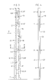
- Fig.1 ein in perspektivischer Ansicht dargestelltes Lagergestell mit drei im Abstand zueinander angeordneten Standsäulen,
- Fig.2 das in Seitenansicht dargestellte Lagergestell gemäss Fig.1,
- Fig.3 eine in Ansicht dargestellte Standsäule für das Lagergestell gemäss Fig.1,
- Fig.4 die in Seitenansicht gemäss Pfeilrichtung X in Fig.3 dargestellte Standsäule,
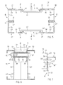
- Fig.5 die gemäss der Linie V-V in Fig.3 im Profilquerschnitt dargestellte Standsäule,
- Fig.6 ein gemäss Pfeilrichtung X' in Fig.2 in Seitenansicht dargestelltes Fusselement mit der daran angeordneten und befestigten Standsäule des Lagergestells, und
- Fig.7 ein Variante der Befestigung der Standsäule am Fusselement.
- Fig.1 zeigt in perspektivischer Seitenansicht ein in der Gesamtheit mit 100 bezeichnetes Lagergestell, welches als einseitig belastbares Freiträger-Lagergestell zur Aufnahme einer schematisch dargestellten Last 110 ausgebildet ist.
- Das Lagergestell 100 umfasst im dargestellten Ausführungsbeispiel drei im Abstand zueinander angeordnete Standsäulen 10, 10' und 10", welche jeweils mit einem orthogonal dazu angeordneten und entsprechend ausgebildeten Fusselement 15,15' und 15" am Boden abgestützt sind.
- Zwischen den Standsäulen 10 und 10' sowie 10'und 10" ist jeweils mindestens eine, die einzelnen Standsäulen miteinander verbindende, schematisch dargestellte Verstrebung 16,16' vorgesehen. Die als Stabilisierung des Lagergestells 100 ausgebildeten und in Fig.1 durch die strichpunktierten Linien dargestellten Verstrebungen 16 und 16' sind vorzugsweise höhenversetzt zueinander zwischen den Standsäulen 10,10' und 10" angeordnet und befestigt. Die Befestigung der Verstrebungen 16,16' an den mit entsprechenden Laschen 6,6',7,7' und 8,8' (Fig.2) versehenen Standsäulen 10,10',10" erfolgt beispielsweise durch eine nicht näher dargestellte Schraub- oder Schweissverbindung.
- Im dargestellten Ausführungsbeispiel sind an jeder einzelnen Standsäule 10;10' und 10" vier in der Höhe versetzt zueinander angeordnete Tragarme 11,12,13,14 und 11',12',13',14' sowie 11",12",13",14" angeordnet und jeweils durch mindestens einen schematisch dargestellten Steckbolzen 17,17',17" gehalten. Zur stufenweisen Verstellung der Tragarme und zur Aufnahme der in Fig.1 an jeder Standsäule nur einmal bezeichneten Steckbolzen 17,17',17" ist jede einzelne Standsäule 10, 10'und 10", wie in Fig.3 schematisch dargestellt, in vertikaler Richtung mit in Abständen zueinander verteilt angeordneten und entsprechend ausgebildeten Ausnehmungen oder Durchbrüchen versehen. Die in Verbindung mit Fig.3 noch zu beschreibenden Ausnehmungen in den einzelnen Vertikalträgern der Standsäulen 10,10',10" sind dabei korrespondierend zueinander angeordnet, so dass beim Anbringen der einzelnen Tragarme 11,12,13,14 und 11',12',13',14' sowie 11",12",13",14" die ohne weitere Hilfmittel einsteckbaren Steckbolzen 17,17', 17" die entsprechende Standsäule im wesentlichen quer zur vertikalen Richtung durchdringen.
- In Fig.2 ist das Lagergestell 100 in Seitenansicht dargestellt und man erkennt die Standsäule 10 mit den seitlich daran, in vertikaler Richtung im Abstand zueinander angeordneten Tragarmen 11,12,13 und 14 sowie das Fusselement 15.
- Die Standsäule 10 ist beispielsweise durch eine Schraubverbindung 60,60';61,61' am Fusselement 15 befestigt. Das Fusselement 15 hat zwei Längsträger 50,50' und ist an seiner Stirnseite in nicht näher dargestellter Weise mit einer Platte 52 verschlossen. Die Fusselemente 15',15" sind analog ausgebildet.
- Die spezielle Ausgestaltung der Schraubverbindungen 60, 60' und 61,61' für die Befestigung - Standsäule am Fusselement - werden später noch in Verbindung mit Fig.6 im einzelnen beschrieben.
- An dieser Stelle sei darauf hingewiesen, dass die Standsäulen 10' und 10" mit den einzelnen daran angeordneten Elementen ebenfalls analog ausgebildet sind.
- Wie in Fig.2 durch die strichpunktierten Linien schematisch dargestellt, sind bei einer Variante an der Standsäule 10 zwei weitere, in vertikaler Richtung im Abstand zueinander angeordnete Tragarme 112,113 sowie ein zweites Fusselement 115 vorgesehen. Bei diesem Ausführungsbeispiel ist das aus den einzelnen, in Reihe angeordneten Standsäulen und mit den Tragarmen 11,12,13,14 und 112,113 versehene Lagergestell 100' als zweiseitig belastbares Freiträger-Lagergestell ausgebildet.
- In Fig.3 ist die Standsäule 10 in Ansicht dargestellt und man erkennt einen ersten Vertikalträger 20 sowie einen zweiten Vertikalträger 30. Die beiden Vertikalträger 20,30 sind durch in vertikaler Richtung in entsprechenden Abständen zueinander angeordneten Abstandhaltern 40,40';41,41';42,42' und 43,43' derart miteinander verbunden, dass die beiden Vertikalträger 20 und 30 ausgehend vom Fussteil F die mit einem Spalt C sich nach oben zum Kopfteil K verjüngende Standsäule 10 bilden.
- An den Abstandhaltern 41,41';42,42' und 43,43' sind die Laschen 6,6';7,7' und 8,8' angeordnet, welche für die Befestigung der in Fig.1 schematisch dargestellten Verstrebung 16,16' vorgesehen und ausgebildet sind.
- In jedem Vertikalträger 20,30 sind in vertikaler Richtung und in gleichmässigen, nicht näher bezeichneten Abständen zueinander angeordnete Ausnehmungen vorgesehen, wobei die Ausnehmungen in dem einen Vertikalträger 30 generell mit 18, 18' und in dem anderen Vertikalträger 20 generell mit 19,19' bezeichnet sind.
- Die einzelne Ausnehmung 18 ist mit ihrer nicht näher bezeichneten Innenkante in bezug zu der Aussenkante 36 des Vertikalträgers 30 unter einem Winkel a angeordnet. Der Winkel a wird beispielsweise mit 10° gewählt, so dass der einzelne, mit einem entsprechend ausgebildeten Halteteil 5 (nur einmal in Fig.2 bezeichnet) versehene Tragarm 12 mit einer vorgegebenen, geringfügig nach oben gerichteten Schräge am Vertikalträger 30 angeordnet und durch den Steckbolzen 17' in seiner Lage gehalten ist.
- In Fig.4 ist die Standsäule 10 in Seitenansicht gemäss Pfeilrichtung X (Fig.3) dargestellt und man erkennt den einen aus zwei Profilkörpern 21,21' gebildeten Vertikalträger 20 sowie die in vertikaler Richtung im Abstand zueinander an den Abstandhaltern 41,41';42,42' und 43,43' angeordneten Laschen 6,6';7,7' und 8,8' für die Verstrebungen 16,16' (Fig.1).
- Fig.5 zeigt die Standsäule 10 im Profilquerschnitt gemäss der Linie V-V in Fig.3 in grösserem Massstab und man erkennt die ebenfalls im Profilquerschnitt dargestellten Profilkörper 21, 21' des einen Vertikalträgers 20 und die Profilkörper 31,31' des anderen Vertikalträgers 30 sowie die die beiden Vertikalträger 20 und 30 miteinander verbindenden Abstandhalter 41 und 41'. Der einzelne Abstandhalter 41,41' liegt dabei mit entsprechend umgebogenen Teilstücken 44,44' (nur einmal bezeichnet) an der nicht bezeichneten Innenseite der Profilkörper 21,21' und 31,31' an.
- Der Vertikalträger 20 umfasst den ersten und den zweiten Profilkörper 21,21'. Im Profilquerschnitt ist der Profilkörper 21 im wesentlichen [- förmig ausgebildet und hat zwei parallel zueinander angeordnete Schenkel 23 und 25 sowie einen die Schenkel 23,25 miteinander verbindenden Flansch 24. Der eine Schenkel 23 ist an seinem freien Ende beispielsweise mit einem umgebogenen Teilstück 22 versehen und in bezug zu dem gegenüberliegenden Schenkel 25 etwas grösser ausgebildet.
- Der Vertikalträger 30 umfasst den ersten und den zweiten Profilkörper 31,31', wobei die aus den einzelnen Teilen gebildeten Profilkörper 31,31' analog dem vorstehend beschriebenen Profilkörper 21,21' ausgebildet sind, welche die Teile 22',23',24' und 25' beziehungsweise die Teile 32,32';33,33'; 34,34' und 35,35' umfassen.
- Weiterhin erkennt man in Fig.5 die in den Schenkeln angeordneten Ausnehmungen 18,18' in dem Vertikalträger 30 sowie die Ausnehmungen 19,19' in dem Vertikalträger 20.
- Die beiden gegenüberliegenden Profilkörper 21,31 sind durch den Abstandhalter 41 und die Profilkörper 21',31' durch den Abstandhalter 41' miteinander verbunden und bilden im wesentlichen die beiden gegenüberliegenden und mit A und A' bezeichneten Längsseiten oder Seitenwände der Standsäule 10. In zusammengebautem Zustand werden die beiden kürzeren Schenkel 25,25' der Profilkörper 21,21' und die beiden kürzeren Schenkel 35,35' der Profilkörper 31,31' durch eine in horizontaler Richtung orientierte Schweissverbindung im Bereich der beiden Stoss-Stellen 27,27' der Flanschen 24,24' miteinander verbunden. Die beiden Flanschen 24 und 24' bilden im wesentlichen die beiden gegenüberliegenden und mit B und B' bezeichneten Schmalseiten oder Stirnwände der Standsäule 10.
- Wie in Fig.5 dargestellt, umfasst der Vertikalträger 20 die beiden Profilkörper 21,21' und der Vertikalträger 30 die beiden Profilkörper 31,31', wobei die beiden Vertikalträger 20, 30 mit den daran angeordneten und befestigen Abstandhaltern 40,40';41,41';42,42' und 43,43' und mit dem entsprechend befestigten Fusselement 15 (nicht dargestellt) zusammen die als eine Baueinheit ausgebildete Standsäule 10 bilden.
- Fig.6 zeigt das gemäss Pfeilrichtung X' in Fig.2 in Seitenansicht dargestellte Fusselement 15 sowie ein Teilstück der beispielsweise lösbar daran befestigen Standsäule 10. Als Ausführungsbeispiel wird nachstehend nur die eine Schraubverbindung 60,60' beschrieben. Die zweite im Abstand dazu angeordnete Schraubverbindung 61,61' ist analog ausgebildet.
- Das in der Gesamtheit mit 15 bezeichnete Fusselement hat die beiden Längsträger 50,50', welche im Profilquerschnitt im wesentlichen [-förmig ausgebildet und mit ihren vertikalen Stegen 51,51' gegeneinander gerichtet, im Abstand zueinander angeordnet sind. Zwischen den beiden Längsträgern 50,50' ist die Standsäule 10 angeordnet und man erkennt die beiden Profilkörper 21,21' des einen Vertikalträgers 20.
- Zur besseren Darstellung der einzelnen Schraubverbindung 60 sind die beiden Profilkörper 21,21' im oberen Bereich aufgebrochen und im Schnitt dargestellt. Die einzelne Schraubverbindung 60 umfasst im wesentlichen einen Gewindebolzen 57, eine Mutter 59 mit entsprechend zugeordneten Unterleg-Scheiben 54,58 sowie zwei koaxial ineinander gesteckte Distanzhülsen 55,56. Die erste Distanzhülse 55 ist dabei zwischen den gegenüberliegenden Schenkeln 23,23' der Profilkörper 21,21' angeordnet und reicht von der einen Innenwand 26 bis zur anderen Innenwand 26'. Die erste Distanzhülse 55 wird von der zweiten Distanzhülse 56 durchdrungen, wobei die zweite Distanzhülse 56 die Stege 51,51' der Längsträger 50,50' durchdringt und an beiden Enden mit der Aussenseite der Stege 51,51' abschliesst. Die erste Distanzhülse 55 kann beispielsweise durch eine Heftschweissung an der jeweiligen Innenwand 26,26' befestigt werden. Die im Abstand dazu angeordnete Schraubverbindung 60' sowie die Schraubverbindungen 61,61' (Fig.2) sind analog ausgebildet.
- Mittels des die zweite Distanzhülse 56 durchdringenden Gewindebolzens 57 werden die beiden Längsträger 50,50' mit der dazwischen angeordneten Standsäule 10 fest verschraubt. Durch die besondere Ausgestaltung der Schraubverbindung 60, 60' und 61,61' wird eine stabile Verbindung der Standsäule 10 mit dem Fusselement 15 erreicht, ohne dass bei der Montage durch die Wirkung der Schraubkraft eine Verformung der Längsträger 50,50' und der dazwischen angeordneten Vertikalträger 20,30 erfolgt.
- Fig.7 zeigt in Schnittansicht und als Ausschnitt eine Variante der Befestigung 60" der Standsäule 10 am Fusselement 15 und man erkennt den einen Längsträger 50', ein Teilstück der Standsäule 10 sowie den Gewindebolzen 57' mit der Unterleg-Scheibe 54'. Bei diesem Ausführungsbeispiel ist zwischen dem Schenkel 23' des Profilkörpers 21' und dem Steg 51' des Längsträgers 50' eine entsprechend ausgebildeten Verstärkungsplatte 62 vorgesehen. Die Verstärkungsplatte 62 kann entweder am Steg 51' des Längsträgers 50' oder aber am Schenkel 23' des Profilkörpers 21' durch eine entsprechende Heft-Schweissung befestigt werden. Bei einem nicht dargestellten Ausführungsbeispiel kann zusätzlich auf der der Unterleg-Scheibe 54' zugesandten Seite des Steges 51' eine weitere Verstärkungsplatte 62 angeordnet werden.
- Abweichend von der Befestigung gemäss Fig.6 sind bei der in Fig.7 dargestellten Ausführung keine Distanzhülsen 55,56 vorgesehen und der Gewindebolzen 57' wird mit der Scheibe 58' und Mutter 59' direkt mit dem Schenkel 23' des Profilkörpers 21' verschraubt.
- Bei der Schraubverbindung gemäss Fig.6 sind somit vier, die Teile 20,50,50' durchdringende und an der jeweiligen Aussenseite verschraubte Gewindebolzen 57 erforderlich.
- Bei der Schraubverbindung gemäss Fig.7 sind acht Gewindebolzen 57' erforderlich, welche lediglich den Steg 51' des Längsträgers 50' sowie den Schenkel 23' des Profilkörpers 21' durchdringen und an der Innenseite 26' verschraubt sind.
Claims (8)
Applications Claiming Priority (2)
| Application Number | Priority Date | Filing Date | Title |
|---|---|---|---|
| CH2604/90 | 1990-08-09 | ||
| CH2604/90A CH681883A5 (de) | 1990-08-09 | 1990-08-09 |
Publications (2)
| Publication Number | Publication Date |
|---|---|
| EP0470296A1 true EP0470296A1 (de) | 1992-02-12 |
| EP0470296B1 EP0470296B1 (de) | 1997-01-29 |
Family
ID=4237494
Family Applications (1)
| Application Number | Title | Priority Date | Filing Date |
|---|---|---|---|
| EP90124709A Expired - Lifetime EP0470296B1 (de) | 1990-08-09 | 1990-12-19 | Freiträger-Lagergestell |
Country Status (5)
| Country | Link |
|---|---|
| EP (1) | EP0470296B1 (de) |
| AT (1) | ATE148314T1 (de) |
| CH (1) | CH681883A5 (de) |
| DE (1) | DE59010642D1 (de) |
| ES (1) | ES2096573T3 (de) |
Cited By (6)
| Publication number | Priority date | Publication date | Assignee | Title |
|---|---|---|---|---|
| WO2002074139A1 (en) * | 2001-03-20 | 2002-09-26 | The Storage Equipment Manufacturing Company Limited | Storage |
| EP1369061A1 (de) * | 2002-06-07 | 2003-12-10 | METAL WORK S.r.l. | Modulare Struktur für Möbel |
| FR2862742A1 (fr) * | 2003-11-20 | 2005-05-27 | Tonnellerie Baron | Dispositif pour supporter des barriques |
| EP1624127A1 (de) | 2004-08-06 | 2006-02-08 | Sipag | Stütze mit einem rechteckigen Querschnitt für ein Lagersystem und ein Lagersystem mit mindestens einer der beschriebenen Stützen |
| EP2180567A1 (de) | 2008-10-22 | 2010-04-28 | CTS Cable Tray Systems SAS | Erdbebensicherer Konsolenarm |
| AT16745U1 (de) * | 2019-05-27 | 2020-07-15 | Tgw Mechanics Gmbh | Regallagersystem und Regalrahmenteil für ein Regallagersystem |
Families Citing this family (3)
| Publication number | Priority date | Publication date | Assignee | Title |
|---|---|---|---|---|
| DE29910201U1 (de) | 1999-06-11 | 1999-08-05 | BRASS Laden-Regalbau GmbH, 74235 Erlenbach | Kragarmregalvorrichtung |
| CN111449370B (zh) * | 2020-05-27 | 2020-12-29 | 浙江和生荣智能科技有限公司 | 一种自动化制鞋生产线 |
| CN113247501B (zh) * | 2021-05-25 | 2022-11-22 | 一汽解放汽车有限公司 | 一种立体库 |
Citations (3)
| Publication number | Priority date | Publication date | Assignee | Title |
|---|---|---|---|---|
| US3512654A (en) * | 1968-05-09 | 1970-05-19 | Jarke Corp | Modular cantilever adjustable arm rack and joint assembly |
| DE8901182U1 (de) * | 1989-02-03 | 1989-05-11 | Ge We Systemeinrichtungen GmbH für Büro, Betrieb, Lager, 3501 Ahnatal | Lagerregal mit lösbarer Klemmverbindung |
| DE8912420U1 (de) * | 1989-09-12 | 1990-01-04 | Sipag Storagesystems and Industrial Products AG, Zürich | Anbauregal od.dgl. Lagervorrichtung, insbesondere für Langgut |
-
1990
- 1990-08-09 CH CH2604/90A patent/CH681883A5/de not_active IP Right Cessation
- 1990-12-19 EP EP90124709A patent/EP0470296B1/de not_active Expired - Lifetime
- 1990-12-19 ES ES90124709T patent/ES2096573T3/es not_active Expired - Lifetime
- 1990-12-19 DE DE59010642T patent/DE59010642D1/de not_active Expired - Lifetime
- 1990-12-19 AT AT90124709T patent/ATE148314T1/de not_active IP Right Cessation
Patent Citations (3)
| Publication number | Priority date | Publication date | Assignee | Title |
|---|---|---|---|---|
| US3512654A (en) * | 1968-05-09 | 1970-05-19 | Jarke Corp | Modular cantilever adjustable arm rack and joint assembly |
| DE8901182U1 (de) * | 1989-02-03 | 1989-05-11 | Ge We Systemeinrichtungen GmbH für Büro, Betrieb, Lager, 3501 Ahnatal | Lagerregal mit lösbarer Klemmverbindung |
| DE8912420U1 (de) * | 1989-09-12 | 1990-01-04 | Sipag Storagesystems and Industrial Products AG, Zürich | Anbauregal od.dgl. Lagervorrichtung, insbesondere für Langgut |
Cited By (9)
| Publication number | Priority date | Publication date | Assignee | Title |
|---|---|---|---|---|
| WO2002074139A1 (en) * | 2001-03-20 | 2002-09-26 | The Storage Equipment Manufacturing Company Limited | Storage |
| EP1369061A1 (de) * | 2002-06-07 | 2003-12-10 | METAL WORK S.r.l. | Modulare Struktur für Möbel |
| FR2862742A1 (fr) * | 2003-11-20 | 2005-05-27 | Tonnellerie Baron | Dispositif pour supporter des barriques |
| WO2005051126A1 (fr) * | 2003-11-20 | 2005-06-09 | Tonnellerie Baron | Dispositif pour supporter des barriques |
| EP1624127A1 (de) | 2004-08-06 | 2006-02-08 | Sipag | Stütze mit einem rechteckigen Querschnitt für ein Lagersystem und ein Lagersystem mit mindestens einer der beschriebenen Stützen |
| FR2873907A1 (fr) | 2004-08-06 | 2006-02-10 | Sipag Sa | Montant de section rectangulaire destine a un systeme de stockage et systeme de stockage equipe d'au moins un montant tel que precipite |
| EP2180567A1 (de) | 2008-10-22 | 2010-04-28 | CTS Cable Tray Systems SAS | Erdbebensicherer Konsolenarm |
| AT16745U1 (de) * | 2019-05-27 | 2020-07-15 | Tgw Mechanics Gmbh | Regallagersystem und Regalrahmenteil für ein Regallagersystem |
| US11629007B2 (en) | 2019-05-27 | 2023-04-18 | Tgw Mechanics Gmbh | Rack storage system and rack frame part for a rack storage system |
Also Published As
| Publication number | Publication date |
|---|---|
| ES2096573T3 (es) | 1997-03-16 |
| ATE148314T1 (de) | 1997-02-15 |
| CH681883A5 (de) | 1993-06-15 |
| EP0470296B1 (de) | 1997-01-29 |
| DE59010642D1 (de) | 1997-03-13 |
Similar Documents
| Publication | Publication Date | Title |
|---|---|---|
| EP1977935B1 (de) | Kraftfahrzeug-Rahmenstruktur und Crashbox dafür | |
| DE202020105707U1 (de) | Photovoltaikanlage zur Verankerung im Erdreich | |
| EP2698488A2 (de) | Trägerverbundsystem | |
| EP3464753A1 (de) | Vertikalträgerbaugruppe für einen schwerlast-gerüstturm | |
| EP0470296A1 (de) | Freiträger-Lagergestell | |
| CH717061A1 (de) | Struktursystem zum modularen Aufbau von Regalen und Regal. | |
| DE2722425A1 (de) | Anordnung zur verbindung der teile eines metallischen traggeruestes | |
| DE2526660C3 (de) | Gebäudekonstruktion mit einem Raumfachwerk aus Stäben und Knotenstücken und einer Außenhaut | |
| DE102017216892A1 (de) | Gerüstelement zur Anbindung an eine scheibenförmige Anschlussplatte sowie Gerüst-Teil mit einem solchen Gerüstelement | |
| EP0021031A2 (de) | Klemmbolzenregal | |
| EP1457618A1 (de) | Gitterrost | |
| EP2130993B1 (de) | Abstützvorrichtung, insbesondere Unterstellbock | |
| DE20010401U1 (de) | Halter zur Befestigung von Plattenmaterial, insbesondere von Glasscheiben an Standsäulen o.dgl. | |
| DE102015108298B4 (de) | Steckbarer Gitterrost und Verfahren zu seiner Herstellung | |
| DE29924191U1 (de) | Regal | |
| DE69500153T2 (de) | Strukturelement für einen Gestellrahmen eines Schaltschranks | |
| DE2543809C3 (de) | ||
| AT18252U1 (de) | Tragkonstruktionsmontagesystem für Photovoltaik-Module | |
| EP4173476A1 (de) | Hochbeet mit seitenwänden und querstreben | |
| EP4258947A1 (de) | Kragarmregal | |
| DE2556365A1 (de) | Stuetzenturm | |
| DE69319146T2 (de) | Zusammenstellbare regaleinheit | |
| DE202019102020U1 (de) | Regalsystem | |
| DE10314825B3 (de) | Reifenregal | |
| DE2614701C2 (de) | Flanschverbindung von Zuggabelholmen mit Längsträgern von Anhängern |
Legal Events
| Date | Code | Title | Description |
|---|---|---|---|
| PUAI | Public reference made under article 153(3) epc to a published international application that has entered the european phase |
Free format text: ORIGINAL CODE: 0009012 |
|
| AK | Designated contracting states |
Kind code of ref document: A1 Designated state(s): AT BE CH DE DK ES FR GB GR IT LI LU NL SE |
|
| 17P | Request for examination filed |
Effective date: 19920714 |
|
| 17Q | First examination report despatched |
Effective date: 19940510 |
|
| GRAG | Despatch of communication of intention to grant |
Free format text: ORIGINAL CODE: EPIDOS AGRA |
|
| GRAH | Despatch of communication of intention to grant a patent |
Free format text: ORIGINAL CODE: EPIDOS IGRA |
|
| GRAH | Despatch of communication of intention to grant a patent |
Free format text: ORIGINAL CODE: EPIDOS IGRA |
|
| GRAA | (expected) grant |
Free format text: ORIGINAL CODE: 0009210 |
|
| AK | Designated contracting states |
Kind code of ref document: B1 Designated state(s): AT BE CH DE DK ES FR GB GR IT LI LU NL SE |
|
| PG25 | Lapsed in a contracting state [announced via postgrant information from national office to epo] |
Ref country code: NL Free format text: LAPSE BECAUSE OF FAILURE TO SUBMIT A TRANSLATION OF THE DESCRIPTION OR TO PAY THE FEE WITHIN THE PRESCRIBED TIME-LIMIT Effective date: 19970129 Ref country code: GR Free format text: LAPSE BECAUSE OF FAILURE TO SUBMIT A TRANSLATION OF THE DESCRIPTION OR TO PAY THE FEE WITHIN THE PRESCRIBED TIME-LIMIT Effective date: 19970129 Ref country code: DK Effective date: 19970129 |
|
| REF | Corresponds to: |
Ref document number: 148314 Country of ref document: AT Date of ref document: 19970215 Kind code of ref document: T |
|
| REG | Reference to a national code |
Ref country code: CH Ref legal event code: NV Representative=s name: GERHARD ALTHOFF PATENTANWALT Ref country code: CH Ref legal event code: EP |
|
| ITF | It: translation for a ep patent filed | ||
| GBT | Gb: translation of ep patent filed (gb section 77(6)(a)/1977) |
Effective date: 19970203 |
|
| ET | Fr: translation filed | ||
| REF | Corresponds to: |
Ref document number: 59010642 Country of ref document: DE Date of ref document: 19970313 |
|
| REG | Reference to a national code |
Ref country code: ES Ref legal event code: FG2A Ref document number: 2096573 Country of ref document: ES Kind code of ref document: T3 |
|
| PG25 | Lapsed in a contracting state [announced via postgrant information from national office to epo] |
Ref country code: SE Effective date: 19970429 |
|
| NLV1 | Nl: lapsed or annulled due to failure to fulfill the requirements of art. 29p and 29m of the patents act | ||
| PLBE | No opposition filed within time limit |
Free format text: ORIGINAL CODE: 0009261 |
|
| STAA | Information on the status of an ep patent application or granted ep patent |
Free format text: STATUS: NO OPPOSITION FILED WITHIN TIME LIMIT |
|
| PG25 | Lapsed in a contracting state [announced via postgrant information from national office to epo] |
Ref country code: AT Free format text: LAPSE BECAUSE OF NON-PAYMENT OF DUE FEES Effective date: 19971219 Ref country code: LU Free format text: LAPSE BECAUSE OF NON-PAYMENT OF DUE FEES Effective date: 19971219 |
|
| PG25 | Lapsed in a contracting state [announced via postgrant information from national office to epo] |
Ref country code: BE Free format text: LAPSE BECAUSE OF NON-PAYMENT OF DUE FEES Effective date: 19971231 |
|
| 26N | No opposition filed | ||
| BERE | Be: lapsed |
Owner name: ELVEDI WALTER A. Effective date: 19971231 |
|
| REG | Reference to a national code |
Ref country code: GB Ref legal event code: IF02 |
|
| PGFP | Annual fee paid to national office [announced via postgrant information from national office to epo] |
Ref country code: CH Payment date: 20040505 Year of fee payment: 14 |
|
| PG25 | Lapsed in a contracting state [announced via postgrant information from national office to epo] |
Ref country code: CH Free format text: LAPSE BECAUSE OF NON-PAYMENT OF DUE FEES Effective date: 20041231 Ref country code: LI Free format text: LAPSE BECAUSE OF NON-PAYMENT OF DUE FEES Effective date: 20041231 |
|
| REG | Reference to a national code |
Ref country code: CH Ref legal event code: PL |
|
| PGFP | Annual fee paid to national office [announced via postgrant information from national office to epo] |
Ref country code: FR Payment date: 20051208 Year of fee payment: 16 |
|
| PG25 | Lapsed in a contracting state [announced via postgrant information from national office to epo] |
Ref country code: IT Free format text: LAPSE BECAUSE OF NON-PAYMENT OF DUE FEES;WARNING: LAPSES OF ITALIAN PATENTS WITH EFFECTIVE DATE BEFORE 2007 MAY HAVE OCCURRED AT ANY TIME BEFORE 2007. THE CORRECT EFFECTIVE DATE MAY BE DIFFERENT FROM THE ONE RECORDED. Effective date: 20051219 |
|
| PG25 | Lapsed in a contracting state [announced via postgrant information from national office to epo] |
Ref country code: FR Free format text: LAPSE BECAUSE OF NON-PAYMENT OF DUE FEES Effective date: 20060831 |
|
| REG | Reference to a national code |
Ref country code: FR Ref legal event code: ST Effective date: 20060831 |
|
| REG | Reference to a national code |
Ref country code: GB Ref legal event code: 732E |
|
| PGFP | Annual fee paid to national office [announced via postgrant information from national office to epo] |
Ref country code: GB Payment date: 20071227 Year of fee payment: 18 |
|
| GBPC | Gb: european patent ceased through non-payment of renewal fee |
Effective date: 20081219 |
|
| PG25 | Lapsed in a contracting state [announced via postgrant information from national office to epo] |
Ref country code: GB Free format text: LAPSE BECAUSE OF NON-PAYMENT OF DUE FEES Effective date: 20081219 |
|
| PGFP | Annual fee paid to national office [announced via postgrant information from national office to epo] |
Ref country code: ES Payment date: 20091218 Year of fee payment: 20 |
|
| PGFP | Annual fee paid to national office [announced via postgrant information from national office to epo] |
Ref country code: IT Payment date: 20091224 Year of fee payment: 20 |
|
| PGRI | Patent reinstated in contracting state [announced from national office to epo] |
Ref country code: IT Effective date: 20091201 |
|
| PGFP | Annual fee paid to national office [announced via postgrant information from national office to epo] |
Ref country code: DE Payment date: 20091006 Year of fee payment: 20 |
|
| REG | Reference to a national code |
Ref country code: ES Ref legal event code: FD2A Effective date: 20120424 |
|
| PG25 | Lapsed in a contracting state [announced via postgrant information from national office to epo] |
Ref country code: ES Free format text: LAPSE BECAUSE OF EXPIRATION OF PROTECTION Effective date: 20101220 |
|
| PG25 | Lapsed in a contracting state [announced via postgrant information from national office to epo] |
Ref country code: DE Free format text: LAPSE BECAUSE OF EXPIRATION OF PROTECTION Effective date: 20101219 |