EP0468249B1 - Verfahren zur Herstellung eines CO2-Sensors - Google Patents
Verfahren zur Herstellung eines CO2-Sensors Download PDFInfo
- Publication number
- EP0468249B1 EP0468249B1 EP91111175A EP91111175A EP0468249B1 EP 0468249 B1 EP0468249 B1 EP 0468249B1 EP 91111175 A EP91111175 A EP 91111175A EP 91111175 A EP91111175 A EP 91111175A EP 0468249 B1 EP0468249 B1 EP 0468249B1
- Authority
- EP
- European Patent Office
- Prior art keywords
- working electrode
- na2co3
- electrode
- li2co3
- k2co3
- Prior art date
- Legal status (The legal status is an assumption and is not a legal conclusion. Google has not performed a legal analysis and makes no representation as to the accuracy of the status listed.)
- Expired - Lifetime
Links
- 238000004519 manufacturing process Methods 0.000 title claims description 7
- 238000000034 method Methods 0.000 title claims description 7
- CDBYLPFSWZWCQE-UHFFFAOYSA-L Sodium Carbonate Chemical compound [Na+].[Na+].[O-]C([O-])=O CDBYLPFSWZWCQE-UHFFFAOYSA-L 0.000 claims abstract description 24
- BWHMMNNQKKPAPP-UHFFFAOYSA-L potassium carbonate Chemical compound [K+].[K+].[O-]C([O-])=O BWHMMNNQKKPAPP-UHFFFAOYSA-L 0.000 claims abstract description 18
- 239000011248 coating agent Substances 0.000 claims abstract description 16
- 238000000576 coating method Methods 0.000 claims abstract description 16
- 229910052737 gold Inorganic materials 0.000 claims abstract description 13
- 239000007784 solid electrolyte Substances 0.000 claims abstract description 13
- 229910000029 sodium carbonate Inorganic materials 0.000 claims abstract description 12
- 235000017550 sodium carbonate Nutrition 0.000 claims abstract description 12
- XGZVUEUWXADBQD-UHFFFAOYSA-L lithium carbonate Chemical compound [Li+].[Li+].[O-]C([O-])=O XGZVUEUWXADBQD-UHFFFAOYSA-L 0.000 claims abstract description 11
- 229910052808 lithium carbonate Inorganic materials 0.000 claims abstract description 9
- 235000015320 potassium carbonate Nutrition 0.000 claims abstract description 9
- 229910000027 potassium carbonate Inorganic materials 0.000 claims abstract description 9
- 239000000725 suspension Substances 0.000 claims abstract description 8
- 238000010438 heat treatment Methods 0.000 claims abstract description 7
- UIIMBOGNXHQVGW-UHFFFAOYSA-M Sodium bicarbonate Chemical compound [Na+].OC([O-])=O UIIMBOGNXHQVGW-UHFFFAOYSA-M 0.000 claims abstract description 6
- 238000005516 engineering process Methods 0.000 claims abstract description 6
- 239000010416 ion conductor Substances 0.000 claims abstract description 4
- 229910000032 lithium hydrogen carbonate Inorganic materials 0.000 claims abstract description 4
- 239000011736 potassium bicarbonate Substances 0.000 claims abstract description 3
- 229910000028 potassium bicarbonate Inorganic materials 0.000 claims abstract description 3
- 235000015497 potassium bicarbonate Nutrition 0.000 claims abstract description 3
- TYJJADVDDVDEDZ-UHFFFAOYSA-M potassium hydrogencarbonate Chemical compound [K+].OC([O-])=O TYJJADVDDVDEDZ-UHFFFAOYSA-M 0.000 claims abstract description 3
- 229910000030 sodium bicarbonate Inorganic materials 0.000 claims abstract description 3
- 235000017557 sodium bicarbonate Nutrition 0.000 claims abstract description 3
- MCMNRKCIXSYSNV-UHFFFAOYSA-N Zirconium dioxide Chemical compound O=[Zr]=O MCMNRKCIXSYSNV-UHFFFAOYSA-N 0.000 claims abstract 8
- 229910006587 β-Al2O3 Inorganic materials 0.000 claims abstract 4
- 229910015107 LixWO3 Inorganic materials 0.000 claims abstract 2
- 238000010304 firing Methods 0.000 claims abstract 2
- 239000000843 powder Substances 0.000 claims abstract 2
- 239000000758 substrate Substances 0.000 claims description 6
- 239000000919 ceramic Substances 0.000 abstract description 3
- 239000007787 solid Substances 0.000 abstract description 2
- 229910052640 jadeite Inorganic materials 0.000 abstract 1
- 239000010931 gold Substances 0.000 description 10
- XLYOFNOQVPJJNP-UHFFFAOYSA-N water Chemical compound O XLYOFNOQVPJJNP-UHFFFAOYSA-N 0.000 description 4
- 239000007795 chemical reaction product Substances 0.000 description 3
- 239000000203 mixture Substances 0.000 description 3
- CURLTUGMZLYLDI-UHFFFAOYSA-N Carbon dioxide Chemical compound O=C=O CURLTUGMZLYLDI-UHFFFAOYSA-N 0.000 description 2
- 238000006243 chemical reaction Methods 0.000 description 2
- 238000005245 sintering Methods 0.000 description 2
- 239000007858 starting material Substances 0.000 description 2
- 239000000126 substance Substances 0.000 description 2
- 238000005352 clarification Methods 0.000 description 1
- 239000012084 conversion product Substances 0.000 description 1
- PCHJSUWPFVWCPO-UHFFFAOYSA-N gold Chemical compound [Au] PCHJSUWPFVWCPO-UHFFFAOYSA-N 0.000 description 1
- 239000000463 material Substances 0.000 description 1
- 238000007639 printing Methods 0.000 description 1
- 239000000047 product Substances 0.000 description 1
- 230000000717 retained effect Effects 0.000 description 1
- 238000007650 screen-printing Methods 0.000 description 1
- 230000035945 sensitivity Effects 0.000 description 1
Images
Classifications
-
- G—PHYSICS
- G01—MEASURING; TESTING
- G01N—INVESTIGATING OR ANALYSING MATERIALS BY DETERMINING THEIR CHEMICAL OR PHYSICAL PROPERTIES
- G01N27/00—Investigating or analysing materials by the use of electric, electrochemical, or magnetic means
- G01N27/26—Investigating or analysing materials by the use of electric, electrochemical, or magnetic means by investigating electrochemical variables; by using electrolysis or electrophoresis
- G01N27/403—Cells and electrode assemblies
- G01N27/406—Cells and probes with solid electrolytes
- G01N27/407—Cells and probes with solid electrolytes for investigating or analysing gases
- G01N27/4073—Composition or fabrication of the solid electrolyte
- G01N27/4074—Composition or fabrication of the solid electrolyte for detection of gases other than oxygen
-
- G—PHYSICS
- G01—MEASURING; TESTING
- G01N—INVESTIGATING OR ANALYSING MATERIALS BY DETERMINING THEIR CHEMICAL OR PHYSICAL PROPERTIES
- G01N27/00—Investigating or analysing materials by the use of electric, electrochemical, or magnetic means
- G01N27/26—Investigating or analysing materials by the use of electric, electrochemical, or magnetic means by investigating electrochemical variables; by using electrolysis or electrophoresis
- G01N27/403—Cells and electrode assemblies
- G01N27/404—Cells with anode, cathode and cell electrolyte on the same side of a permeable membrane which separates them from the sample fluid, e.g. Clark-type oxygen sensors
- G01N27/4045—Cells with anode, cathode and cell electrolyte on the same side of a permeable membrane which separates them from the sample fluid, e.g. Clark-type oxygen sensors for gases other than oxygen
Definitions
- the invention relates to a method for producing a CO2 sensor which has an electrochemical cell applied to a substrate in thick-film technology with solid-state ion conductors with a working electrode, a solid electrolyte and a counter electrode. the components applied to the substrate being heated for the sintering of the ceramic components.
- the invention is characterized in that for the production of the working electrode on parts of the solid electrolyte Pt and / or Au is / are printed and then the working electrode is provided with a sensitive coating, for which a suspension of NaHCO3, KHCO3 and / or LiHCO3 is used, which starting material is converted to Na2CO3, K2CO3 or Li2CO3 when heated.
- the specified materials are therefore used as the starting material for the sensitive coating of the working electrode, which are not hygroscopic and which can therefore be produced with exactly reproducible properties. When heated, these are converted into the end products mentioned and desired in each case, and the conversion products formed simultaneously evaporate.
- An important embodiment of the invention is characterized in that the working electrode Pt or Au is printed in line form, preferably meandering or comb-shaped, in such a way that there is as large a contact as possible between the three phases Pt or Au, the sensitive coating and the solid electrolyte .
- the sensitivity of the sensor depends on the three phases touching here (Pt or Au, the sensitive coating and the solid electrolyte) and the line shape of Pt or Au mentioned above increases the contact area of the three phases accordingly and noticeably .
- 2NaHCO3 decays when heated to over 65 ° C in Co2, H2O and Na2CO3. The conversion is complete above about 300 ° C.
- 2KHCO3 decomposes when heated to about 200 ° C in K2CO3, H2O and CO2.
- LiHCO3 is stable up to approx. 30 ° C. 2LiHCO3 disintegrates on further heating in Li2CO3 and H2O and CO2.
- a heating layer is preferably printed on a substrate carrying the sensor components at the same time, which ensures the necessary operating temperature of the sensor, preferably on the underside of the substrate, because there is space there.
- the basics of these measures are known per se from the magazine "Battelle-Information”.
- Claim 4 specifies the basic composition of its solid electrolyte, depending on the composition of its working electrode selected in each case.
- the structure according to one of the options specified in claim 4 is retained in all embodiments.
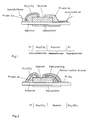
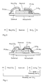
- FIGS. 1-4 For clarification, the structure of the electrochemical cell in question was given in FIGS. 1-4 in accordance with the example of the figure in question, the phase boundaries being separated from one another by vertical lines.
- a cell voltage is measured, which indicates the concentration of CO2 and O2 together.
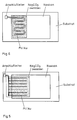
- FIG. 5 and 6 show the comb-like shape (FIG. 5) of Pt or Au as part of the working electrode or its meandering shape (FIG. 6). These line shapes serve to enlarge the contact areas between the three phases Pt and Au, the sensitive coating, e.g. Na2CO3, and the solid electrolyte, e.g. Nasicon.
- the sensitive coating e.g. Na2CO3
- the solid electrolyte e.g. Nasicon.
- the operating temperature of the sensor which is achieved with the help of the heating layer, is between about 100 and 600 ° C, depending on the embodiment.
- the sensor is in thick-film technology, i.e. H. Made in screen printing technology with subsequent heating of the applied layers for the sintering of the ceramics.
Landscapes
- Chemical & Material Sciences (AREA)
- Life Sciences & Earth Sciences (AREA)
- Health & Medical Sciences (AREA)
- Biochemistry (AREA)
- General Physics & Mathematics (AREA)
- Electrochemistry (AREA)
- Physics & Mathematics (AREA)
- Analytical Chemistry (AREA)
- Molecular Biology (AREA)
- General Health & Medical Sciences (AREA)
- Chemical Kinetics & Catalysis (AREA)
- Immunology (AREA)
- Pathology (AREA)
- Measuring Oxygen Concentration In Cells (AREA)
- Compositions Of Oxide Ceramics (AREA)
- Investigating Or Analysing Materials By Optical Means (AREA)
- Investigating Or Analyzing Materials By The Use Of Fluid Adsorption Or Reactions (AREA)
Description
- Die Erfindung betrifft ein Verfahren zur Herstellung eines CO₂-Sensors, der eine in Dickschichttechnik auf ein Substrat aufgebrachte elektrochemische Zelle mit Festkörperionenleitern mit einer Arbeitselektrode, einem Festelektrolyten und einer Gegenelektrode aufweist. wobei die auf das Substrat aufgebrachten Bestandteile zwecks Sinterung der keramischen Bestandteile erwärmt werden.
- Zum Stand der Technik wird auch verwiesen auf einen Aufsatz von Maruyama und Mitarbeitern, erschienen in Solid State lonics 23 (1987), Seiten 107 bis 112. Dort wird ein CO₂-Sensor beschrieben, der aus Festkörperionenleitern besteht, wobei Na₂CO₃, Nasicon und Goldpaste in Tablettenform verwendet werden.
- Es hat sich jedoch herausgestellt, daß man für die Arbeitselektrode Na₂CO₃, K₂CO₃ oder Li₂CO₃ in Dickschichttechnik nicht direkt aufdrucken kann, weil diese Substanzen hygroskopisch sind. Bei der Herstellung der Suspension zum Bedrucken wären somit die rheologischen Eigenschaften der Paste oder Suspension nicht reproduzierbar, weil sich deren Viskosität ändern kann.
- Ausgehend von einem Verfahren mit den eingangs genannten Merkmalen liegt daher der Erfindung die Aufgabe zugrunde, dieses so zu führen, daß die sensitive Beschichtung der Arbeitselektrode mit reproduzierbaren Eigenschaften hergestellt wird.
- Zur Lösung dieser Aufgabe ist die Erfindung dadurch gekennzeichnet, daß zur Herstellung der Arbeitselektrode auf Teilen des Festelektrolyten Pt und/oder Au aufgedruckt wird/werden und anschließend die Arbeitselektrode mit einer sensitiven Beschichtung versehen wird, für die als Ausgangsmaterial eine Suspension aus NaHCO₃, KHCO₃ und/oder LiHCO₃ verwendet wird, welches Ausgangsmaterial beim Erwärmen zu Na₂CO₃, K₂CO₃ bzw. Li₂CO₃ umgesetzt wird.
- Man verwendet somit als Ausgangsmaterial für die sensitive Beschichtung der Arbeitselektrode die angegebenen Materialien, die nicht hygroskopisch sind und die sich daher mit exakt reproduzierbaren Eigenschaften herstellen lassen. Diese werden beim Erhitzen in die genannten und jeweils gewünschten Endprodukte umgewandelt, wobei gleichzeitig entstehende Umwandlungsprodukte verdampfen.
- Die Beständigkeit der sensitiven Beschichtung der Arbeitselektrode wird weiterhin erhöht, wenn der Ausgangssuspension für die Arbeitselektrode vor dem Brennen MCO₃ oder A₂CO₃ in Anteilen von bis zu 10 Mol% zugemischt wird, vorzugsweise in Anteilen von 1 bis 8 Mol% mit M = Sr oder Ba und A = Li oder K. Diese Zumischung erhöht gleichzeitig die elektrische Leitfähigkeit der betreffenden Substanzen.
- Eine wichtige Ausgestaltung der Erfindung ist dadurch gekennzeichnet, daß bei der Arbeitselektrode Pt oder Au in Linienform, vorzugsweise mäanderförmig oder kammförmig, derart aufgedruckt wird, daß sich eine möglichst großflächige Berührung zwischen den drei Phasen Pt bzw. Au, der sensitiven Beschichtung und dem Festelektrolyten ergibt. Die Empfindlichkeit des Sensors ist an dieser Stelle nämlich von den sich hier berührenden drei Phasen (Pt bzw. Au, der sensitiven Beschichtung und dem Festelektrolyten) abhängig und durch die erwähnte Linienform von Pt bzw. Au wird die Berührungsfläche der drei Phasen entsprechend und fühlbar erhöht.
- Bezüglich der Umwandlung der Ausgangsprodukte in die Endprodukte beim Erwärmen wird folgendes aufgeführt:
- 2NaHCO₃ zerfällt beim Erwärmen auf über 65°C in Co₂, H₂O und Na₂CO₃. Oberhalb von etwa 300°C ist die Umwandlung vollständig.
- 2KHCO₃ zerfällt beim Erhitzen auf etwa 200°C in K₂CO₃, H₂O und CO₂.
- LiHCO₃ ist bis ca. 30°C stabil. 2LiHCO₃ zerfällt beim weiteren Erwärmen in Li₂CO₃ und H₂O und CO₂.
- Beim Erwärmen ergibt sich also das jeweils gewünschte Endprodukt, und zwar zusammen mit Wasserdampf und CO₂, die gasförmig entweichen.
- Bei der Herstellung des Sensors wird auf ein die Sensorkomponenten tragendes Substrat gleichzeitig vorzugsweise eine Heizschicht mit aufgedruckt, die für die notwendige Betriebstemperatur des Sensors sorgt, und zwar vorzugsweise auf die Unterseite des Substrats, weil dort Platz ist. Diese Maßnahmen sind durch die Zeitschrift "Battelle-Information" in ihren Grundzügen an sich bekannt.
- Die Patentansprüche 4 bis 8 charakterisieren bevorzugte Ausführungsformen eines nach dem erfindungsgemäßen Verfahren hergestellten Sensors.
- Anspruch 4 gibt dabei die grundsätzliche Zusammensetzung seines Festelektrolyten an, abhängig von der jeweils gewählten Zusammensetzung seiner Arbeitselektrode. Der Aufbau nach einer der in Anspruch 4 angegebenen Möglichkeiten bleibt bei allen Ausführungsformen beibehalten.
- Die Ansprüche 5 bis 8 kennzeichnen Varianten der Zusammensetzung der Gegenelektrode des Sensors, wobei mit der Ausführungsform nach Anspruch 8 zusätzlich O₂ gemessen werden kann.
- Die Erfindung wird im folgenden anhand von Ausführungsbeispielen näher erläutert, aus denen sich weitere wichtige Merkmale ergeben. Es zeigt:
- Fig. 1 - 4
- schematisch vier Ausführungsformen von erfindungsgemäßen CO₂-Sensoren, jeweils in einer teilweise geschnittenen Seitenansicht und
- Fig. 5 und 6
- Draufsichten auf die Sensoren zur Darstellung der Kammform (Fig. 5) bzw. Mäanderform (Fig. 6) des Pt- bzw. Au-Anteils der Arbeitselektrode der Sensoren.
- In Fig. 1 - 4 wurde zur Vereinfachung für die Arbeitselektrode nur Pt bzw. Au (porös) mit einer Beschichtung aus Na₂CO₃ eingezeichnet und für den Festelektrolyten wurde jeweils nur Nasicon angegeben. Diesbezüglich sind aber alle Kombinationen nach Patentanspruch 4 möglich.
- Bezüglich der Gegenelektrode sind bei dem Ausführungsbeispiel nach Fig. 2 alle Kombinationen nach Patentanspruch 5 möglich.
- In den Fig. 1, 3 und 4 wurden die jeweils möglichen Kombinationen der Gegenelektrode in diesen Figuren angegeben.
- Zur Verdeutlichung wurde unter den Fig. 1 - 4 jeweils der Aufbau der betreffenden elektrochemischen Zelle entsprechend dem Beispiel der betreffenden Figur angegeben, wobei die Phasengrenzen durch senkrechte Striche voneinander getrennt sind.
- Es ergibt sich, daß in Fig. 1 und 3 effektiv nur der Partialdruck von CO₂ gemessen wird.
- In Fig. 2 wird eine Zellspannung gemessen, die die Konzentration von CO₂ und O₂ zusammen angibt.
- In Fig. 4 wird die Konzentration von CO₂ und zusätzlich und unabhängig davon diejenige von O₂ gemessen.
- Die Fig. 5 und 6 zeigen die kammartige Form (Fig. 5) von Pt oder Au als Teil der Arbeitselektrode bzw. deren Mäanderform (Fig. 6). Diese Linienformen dienen zur Vergrößerung der Berührungsflächen zwischen den drei Phasen Pt bzw. Au, der sensitiven Beschichtung, z.B. Na₂CO₃, und dem Festelektrolyt, z.B. Nasicon.
- Die Betriebstemperatur des Sensors, die mit Hilfe der Heizschicht erzielt wird, liegt je nach Ausführungsform zwischen etwa 100 und 600 °C.
- Der Sensor wird in Dickschichttechnik, d. h. in Siebdrucktechnik hergestellt mit anschließender Erwärmung der aufgebrachten Schichten zwecks Sintern der Keramiken.
Claims (8)
- Verfahren zur Herstellung eines CO₂-Sensors, der eine in Dickschichttechnik auf ein Substrat aufgebrachte elektrochemische Zelle mit Festkörperionenleitern mit einer Arbeitselektrode, einem Festelektrolyten und einer Gegenelektrode aufweist, wobei die auf das Substrat aufgebrachten Bestandteile erwärmt werden,
dadurch gekennzeichnet,
daß zur Herstellung der Arbeitselektrode auf Teilen des Festelektrolyten Pt und/oder Au aufgedruckt wird/werden und anschließend die Arbeitselektrode mit einer sensitiven Beschichtung versehen wird, für die eine Ausgangssuspension, die NaHCO₃, KHCO₃ und/oder LiHCO₃ aufweist, verwendet wird, welche Ausgangssuspension beim Erwärmen zu Na₂CO₃, K₂CO₃ bzw. Li₂CO₃ umgesetzt wird. - Verfahren nach Anspruch 1,
dadurch gekennzeichnet,
daß der Ausgangssuspension für die Arbeitselektrode vor dem Brennen MCO₃ oder A₂CO₃ und/oder Pulver, was aus dem Festelektrolyten besteht, in Anteilen von bis zu 10 Mol% zugemischt wird, vorzugsweise in Anteilen von 1 bis 8 Mol%, mit M = Sr oder Ba und A = Li oder K. - Verfahren nach Anspruch 1 oder 2,
dadurch gekennzeichnet,
daß bei der Arbeitselektrode Pt oder Au in Linienform derart aufgedruckt wird, daß sich eine möglichst großflächige Berührung zwischen den drei Phasen Pt bzw. Au, der sensitiven Beschichtung und dem Festelektrolyten ergibt. - CO₂-Sensor, hergestellt nach dem Verfahren nach einem der Ansprüche 1 bis 3,
dadurch gekennzeichnet,
daß sein Festelektrolyt aus Nasicon, Na-β-Al₂O₃ oder Titsikon besteht, wenn seine Arbeitselektrode Na₂CO₃ enthält, oder aus Khibinskit, Wadeit oder K-β-Al₂O₃ besteht, wenn seine Arbeitselektrode K₂CO₃ enthält, oder aus Li-β-Al₂O₃ oder LiAlF₆ besteht, wenn seine Arbeitselektrode Li₂CO₃ enthält. - CO₂-Sensor nach Anspruch 4,
dadurch gekennzeichnet,
daß seine Gegenelektrode aus NaxWO₃, KxWO₃ oder LixWO₃ besteht, wenn seine Arbeitselektrode Na₂CO₃, K₂CO₃ bzw. Li₂CO₃ enthält. - CO₂-Sensor nach Anspruch 4,
dadurch gekennzeichnet,
daß seine Gegenelektrode aus Pt und/oder Au besteht. - CO₂-Sensor nach Anspruch 4,
dadurch gekennzeichnet,
daß seine Gegenelektrode aus ZrO₂ mit einer Beschichtung aus Pt und/oder Au besteht. - CO₂-Sensor nach Anspruch 4,
dadurch gekennzeichnet,
daß seine Gegenelektrode aus Pt und/oder Au mit einer mittleren Beschichtung aus ZrO₂ und mit einer oberen Beschichtung aus Pt und/oder Au besteht.
Applications Claiming Priority (2)
| Application Number | Priority Date | Filing Date | Title |
|---|---|---|---|
| DE4022136A DE4022136A1 (de) | 1990-07-11 | 1990-07-11 | Co(pfeil abwaerts)2(pfeil abwaerts)-sensor |
| DE4022136 | 1990-07-11 |
Publications (2)
| Publication Number | Publication Date |
|---|---|
| EP0468249A1 EP0468249A1 (de) | 1992-01-29 |
| EP0468249B1 true EP0468249B1 (de) | 1995-09-27 |
Family
ID=6410110
Family Applications (1)
| Application Number | Title | Priority Date | Filing Date |
|---|---|---|---|
| EP91111175A Expired - Lifetime EP0468249B1 (de) | 1990-07-11 | 1991-07-05 | Verfahren zur Herstellung eines CO2-Sensors |
Country Status (3)
| Country | Link |
|---|---|
| EP (1) | EP0468249B1 (de) |
| AT (1) | ATE128554T1 (de) |
| DE (2) | DE4022136A1 (de) |
Families Citing this family (10)
| Publication number | Priority date | Publication date | Assignee | Title |
|---|---|---|---|---|
| FR2692674B1 (fr) * | 1992-06-18 | 1994-09-09 | Armines | Dispositif de détection de la présence d'un gaz dans une atmosphère. |
| US5413691A (en) * | 1992-12-25 | 1995-05-09 | Tokyuama Corporation | Solid electrolyte gas-sensing device |
| DE4305930C2 (de) * | 1993-02-26 | 1997-07-17 | Roth Technik Gmbh | Festelektrolytsensor zur Messung gasförmiger Anhydride |
| DE19525764A1 (de) * | 1995-07-14 | 1997-01-16 | Siemens Matsushita Components | CO¶2¶-Sensor |
| DE19623487C2 (de) * | 1996-06-12 | 1999-01-07 | Max Planck Gesellschaft | Gavanische Zelle und deren Verwendung als Gassensor |
| JPH10239276A (ja) * | 1996-12-27 | 1998-09-11 | Ngk Insulators Ltd | 一酸化炭素ガスセンサおよび同センサを用いた測定装置 |
| DE19709338C2 (de) * | 1997-03-07 | 1999-03-25 | Zirox Sensoren & Elektronik Gm | Potentiometrischer CO¶2¶-Sensor |
| KR20010072835A (ko) | 1998-08-21 | 2001-07-31 | 추후제출 | 전기 회로 및 구성요소의 프린팅 |
| GB2517902A (en) * | 2013-07-26 | 2015-03-11 | Cambridge Entpr Ltd | Method and apparatus for sensing molecular gases |
| CN104914153B (zh) * | 2015-06-03 | 2018-02-27 | 西安交通大学 | 双层电极式固体电解质co2气体传感器及制备工艺 |
Family Cites Families (2)
| Publication number | Priority date | Publication date | Assignee | Title |
|---|---|---|---|---|
| JPS60256043A (ja) * | 1984-06-01 | 1985-12-17 | Advance Res & Dev Co Ltd | ガスセンサ |
| DE3639802A1 (de) * | 1986-11-21 | 1988-05-26 | Battelle Institut E V | Sensor zur ueberwachung von wasserstoffkonzentrationen in gasen |
-
1990
- 1990-07-11 DE DE4022136A patent/DE4022136A1/de active Granted
-
1991
- 1991-07-05 EP EP91111175A patent/EP0468249B1/de not_active Expired - Lifetime
- 1991-07-05 AT AT91111175T patent/ATE128554T1/de not_active IP Right Cessation
- 1991-07-05 DE DE59106575T patent/DE59106575D1/de not_active Expired - Fee Related
Non-Patent Citations (1)
| Title |
|---|
| A.F. Holleman und E. Wiberg: LEHRBUCH DER ANORGANISCHEN CHEMIE, 40.-46. Auflage, 1958, Walter de Gruyter & Co, Berlin, DE; Seite 428 * |
Also Published As
| Publication number | Publication date |
|---|---|
| EP0468249A1 (de) | 1992-01-29 |
| DE4022136A1 (de) | 1992-01-23 |
| DE4022136C2 (de) | 1992-04-23 |
| DE59106575D1 (de) | 1995-11-02 |
| ATE128554T1 (de) | 1995-10-15 |
Similar Documents
| Publication | Publication Date | Title |
|---|---|---|
| EP0020938B1 (de) | Polarographischer Messfühler für die Bestimmung des Sauerstoffgehaltes in Gasen, insbesondere in Abgasen von Verbrennungsmotoren | |
| DE3048439C2 (de) | Verfahren zur Herstellung eines Festelektrolyt-Sauerstoff-Meßelements mit Schichtstruktur | |
| DE3010632C2 (de) | ||
| DE3315654C2 (de) | ||
| DE2906459A1 (de) | Vorrichtung zur messung der sauerstoffkonzentration in einem fluid | |
| EP0468249A1 (de) | Verfahren zur Herstellung eines CO2-Sensors | |
| DE2365826B2 (de) | Kapazitiver feuchtigkeitsfuehler | |
| DE69123896T2 (de) | pH-Messelektrode und Verfahren zur Herstellung derselben | |
| DE4226948A1 (de) | Kohlendioxidgas-detektorelement | |
| DE69320777T2 (de) | Festelektrolytische Gassensorvorrichtung | |
| DE68928441T2 (de) | Ein Feuchtigkeitssensor unter Verwendung einer elektrochemischen Zelle | |
| DE2838230B2 (de) | Sauerstoff sensor | |
| DE2638775A1 (de) | Elektrochrome anzeigeeinheit und verfahren zu ihrer herstellung | |
| DE2822691A1 (de) | Vorrichtung zum elektrochemischen messen der sauerstoffkonzentration in verbrennungsgasen | |
| DE2402964B2 (de) | ||
| DE3628572A1 (de) | Heizbare lambdasonde | |
| DE4112302A1 (de) | Amperometrischer gassensor zur selektiven bestimmung von partialdrucken eines gases | |
| DE1926445A1 (de) | Elektrode fuer eine Zelle mit Sauerstoffionen-Festelektrolyt | |
| EP0893688A1 (de) | Heizleiter-Schicht mit veränderlichem elektrischen Widerstand und Verfahren zu ihrer Herstellung | |
| DE2040200B2 (de) | Membran fuer elektroden zur messung von ionenkonzentrationen | |
| DE2539001A1 (de) | Verfahren zum aufbringen von elektroden auf keramische elektrochemische gasanalysatoren | |
| DE879920C (de) | Bimorphes UEbertragerelement und Verfahren zu seiner Herstellung | |
| DE2741890A1 (de) | Piezoelektrische keramik | |
| DE19525764A1 (de) | CO¶2¶-Sensor | |
| DE19913921A1 (de) | Gassensorelement |
Legal Events
| Date | Code | Title | Description |
|---|---|---|---|
| PUAI | Public reference made under article 153(3) epc to a published international application that has entered the european phase |
Free format text: ORIGINAL CODE: 0009012 |
|
| AK | Designated contracting states |
Kind code of ref document: A1 Designated state(s): AT BE CH DE DK ES FR GB GR IT LI LU NL SE |
|
| 17P | Request for examination filed |
Effective date: 19920109 |
|
| 17Q | First examination report despatched |
Effective date: 19931122 |
|
| RAP1 | Party data changed (applicant data changed or rights of an application transferred) |
Owner name: ROTH-TECHNIK GMBH & CO. FORSCHUNG FUER AUTOMOBIL- |
|
| GRAA | (expected) grant |
Free format text: ORIGINAL CODE: 0009210 |
|
| ITF | It: translation for a ep patent filed | ||
| AK | Designated contracting states |
Kind code of ref document: B1 Designated state(s): AT BE CH DE DK ES FR GB GR IT LI LU NL SE |
|
| PG25 | Lapsed in a contracting state [announced via postgrant information from national office to epo] |
Ref country code: NL Free format text: LAPSE BECAUSE OF FAILURE TO SUBMIT A TRANSLATION OF THE DESCRIPTION OR TO PAY THE FEE WITHIN THE PRESCRIBED TIME-LIMIT Effective date: 19950927 Ref country code: GR Free format text: LAPSE BECAUSE OF FAILURE TO SUBMIT A TRANSLATION OF THE DESCRIPTION OR TO PAY THE FEE WITHIN THE PRESCRIBED TIME-LIMIT Effective date: 19950927 Ref country code: ES Free format text: THE PATENT HAS BEEN ANNULLED BY A DECISION OF A NATIONAL AUTHORITY Effective date: 19950927 Ref country code: DK Effective date: 19950927 |
|
| REF | Corresponds to: |
Ref document number: 128554 Country of ref document: AT Date of ref document: 19951015 Kind code of ref document: T |
|
| GBT | Gb: translation of ep patent filed (gb section 77(6)(a)/1977) |
Effective date: 19950928 |
|
| REF | Corresponds to: |
Ref document number: 59106575 Country of ref document: DE Date of ref document: 19951102 |
|
| ET | Fr: translation filed | ||
| PG25 | Lapsed in a contracting state [announced via postgrant information from national office to epo] |
Ref country code: SE Effective date: 19951227 |
|
| NLV1 | Nl: lapsed or annulled due to failure to fulfill the requirements of art. 29p and 29m of the patents act | ||
| PG25 | Lapsed in a contracting state [announced via postgrant information from national office to epo] |
Ref country code: LU Free format text: LAPSE BECAUSE OF NON-PAYMENT OF DUE FEES Effective date: 19960731 |
|
| PLBE | No opposition filed within time limit |
Free format text: ORIGINAL CODE: 0009261 |
|
| STAA | Information on the status of an ep patent application or granted ep patent |
Free format text: STATUS: NO OPPOSITION FILED WITHIN TIME LIMIT |
|
| 26N | No opposition filed | ||
| PGFP | Annual fee paid to national office [announced via postgrant information from national office to epo] |
Ref country code: GB Payment date: 19970616 Year of fee payment: 7 |
|
| PGFP | Annual fee paid to national office [announced via postgrant information from national office to epo] |
Ref country code: BE Payment date: 19970624 Year of fee payment: 7 |
|
| PGFP | Annual fee paid to national office [announced via postgrant information from national office to epo] |
Ref country code: AT Payment date: 19970630 Year of fee payment: 7 |
|
| REG | Reference to a national code |
Ref country code: CH Ref legal event code: PUE Owner name: ROTH-TECHNIK GMBH & CO. FORSCHUNG FUER AUTOMOBIL- Ref country code: CH Ref legal event code: NV Representative=s name: KIRKER & CIE SA |
|
| REG | Reference to a national code |
Ref country code: GB Ref legal event code: 732E |
|
| PG25 | Lapsed in a contracting state [announced via postgrant information from national office to epo] |
Ref country code: GB Free format text: LAPSE BECAUSE OF NON-PAYMENT OF DUE FEES Effective date: 19980705 Ref country code: AT Free format text: LAPSE BECAUSE OF NON-PAYMENT OF DUE FEES Effective date: 19980705 |
|
| PG25 | Lapsed in a contracting state [announced via postgrant information from national office to epo] |
Ref country code: BE Free format text: LAPSE BECAUSE OF NON-PAYMENT OF DUE FEES Effective date: 19980731 |
|
| PGFP | Annual fee paid to national office [announced via postgrant information from national office to epo] |
Ref country code: CH Payment date: 19981015 Year of fee payment: 8 |
|
| BERE | Be: lapsed |
Owner name: ROTH-TECHNIK G.M.B.H. & CO. FORSCHUNG FUR AUTOMOB Effective date: 19980731 |
|
| GBPC | Gb: european patent ceased through non-payment of renewal fee |
Effective date: 19980705 |
|
| PG25 | Lapsed in a contracting state [announced via postgrant information from national office to epo] |
Ref country code: LI Free format text: LAPSE BECAUSE OF NON-PAYMENT OF DUE FEES Effective date: 19990731 Ref country code: CH Free format text: LAPSE BECAUSE OF NON-PAYMENT OF DUE FEES Effective date: 19990731 |
|
| REG | Reference to a national code |
Ref country code: CH Ref legal event code: PL |
|
| PGFP | Annual fee paid to national office [announced via postgrant information from national office to epo] |
Ref country code: FR Payment date: 20010709 Year of fee payment: 11 |
|
| PGFP | Annual fee paid to national office [announced via postgrant information from national office to epo] |
Ref country code: DE Payment date: 20010713 Year of fee payment: 11 |
|
| PG25 | Lapsed in a contracting state [announced via postgrant information from national office to epo] |
Ref country code: DE Free format text: LAPSE BECAUSE OF NON-PAYMENT OF DUE FEES Effective date: 20030201 |
|
| PG25 | Lapsed in a contracting state [announced via postgrant information from national office to epo] |
Ref country code: FR Free format text: LAPSE BECAUSE OF NON-PAYMENT OF DUE FEES Effective date: 20030331 |
|
| REG | Reference to a national code |
Ref country code: FR Ref legal event code: ST |
|
| PG25 | Lapsed in a contracting state [announced via postgrant information from national office to epo] |
Ref country code: IT Free format text: LAPSE BECAUSE OF NON-PAYMENT OF DUE FEES;WARNING: LAPSES OF ITALIAN PATENTS WITH EFFECTIVE DATE BEFORE 2007 MAY HAVE OCCURRED AT ANY TIME BEFORE 2007. THE CORRECT EFFECTIVE DATE MAY BE DIFFERENT FROM THE ONE RECORDED. Effective date: 20050705 |