EP0467754B1 - Automatic loading device for a cannon - Google Patents
Automatic loading device for a cannon Download PDFInfo
- Publication number
- EP0467754B1 EP0467754B1 EP91401913A EP91401913A EP0467754B1 EP 0467754 B1 EP0467754 B1 EP 0467754B1 EP 91401913 A EP91401913 A EP 91401913A EP 91401913 A EP91401913 A EP 91401913A EP 0467754 B1 EP0467754 B1 EP 0467754B1
- Authority
- EP
- European Patent Office
- Prior art keywords
- circuit
- ammunition
- control
- bus
- loading
- Prior art date
- Legal status (The legal status is an assumption and is not a legal conclusion. Google has not performed a legal analysis and makes no representation as to the accuracy of the status listed.)
- Expired - Lifetime
Links
Images


Classifications
-
- F—MECHANICAL ENGINEERING; LIGHTING; HEATING; WEAPONS; BLASTING
- F41—WEAPONS
- F41A—FUNCTIONAL FEATURES OR DETAILS COMMON TO BOTH SMALLARMS AND ORDNANCE, e.g. CANNONS; MOUNTINGS FOR SMALLARMS OR ORDNANCE
- F41A9/00—Feeding or loading of ammunition; Magazines; Guiding means for the extracting of cartridges
- F41A9/61—Magazines
- F41A9/64—Magazines for unbelted ammunition
- F41A9/76—Magazines having an endless-chain conveyor
-
- F—MECHANICAL ENGINEERING; LIGHTING; HEATING; WEAPONS; BLASTING
- F41—WEAPONS
- F41A—FUNCTIONAL FEATURES OR DETAILS COMMON TO BOTH SMALLARMS AND ORDNANCE, e.g. CANNONS; MOUNTINGS FOR SMALLARMS OR ORDNANCE
- F41A9/00—Feeding or loading of ammunition; Magazines; Guiding means for the extracting of cartridges
- F41A9/50—External power or control systems
Description
La présente invention est relative aux dispositifs de chargement automatique à magasin tournant pour des canons, notamment des canons équipant des tourelles de véhicules blindés.The present invention relates to automatic loading devices with rotating magazine for guns, in particular guns fitted to turrets of armored vehicles.
Dans les véhicules de ce type, il est nécessaire de disposer d'une grande capacité de stockage de munitions et de pouvoir transférer le plus rapidement possible les munitions stockées dans le magasin tournant, à la chambre de l'arme.In vehicles of this type, it is necessary to have a large capacity for storing ammunition and to be able to transfer the ammunition stored in the revolving magazine as quickly as possible to the chamber of the weapon.
Les véhicules blindés modernes sont amenés à utiliser des munitions de divers types en fonction des situations auxquelles ils sont confrontés sur le terrain.Modern armored vehicles are required to use ammunition of various types depending on the situations they face in the field.
Il est donc également nécessaire de disposer de moyens capables de sélectionner de façon très fiable et en un temps minimal, le type de munition que le chef de pièces décide d'employer.It is therefore also necessary to have means capable of very reliably selecting and in a minimum time, the type of ammunition that the chief of parts decides to use.
Les dispositifs de commande de chargement existants jusqu'à présent sont des dispositifs essentiellement mécaniques et électromécaniques qui nécessitent la plupart du temps une intervention manuelle active de la part de l'opérateur, ce qui rend leur fonctionnement relativement lent et de ce fait inapproprié aux changements souvent extrêmement rapides de situation sur le terrain.The loading control devices existing up to now are essentially mechanical and electromechanical devices which most of the time require active manual intervention on the part of the operator, which makes their operation relatively slow and therefore unsuitable for changes. often extremely fast situation on the ground.
En effet, du fait de l'existence de moyens extrêmement rapides et précis de détection des véhicules blindés, ceux-ci ne disposent que d'un temps très bref pour intervenir sur une cible et pour disparaître avant d'être détectés.In fact, due to the existence of extremely rapid and precise means of detecting armored vehicles, they have only a very short time to intervene on a target and to disappear before being detected.
Par conséquent, les moyens de commande de chargement connus sont souvent inappropriés en raison de leur relative lenteur de fonctionnement.Consequently, the known loading control means are often inappropriate because of their relative slowness of operation.
Il en est ainsi du dispositif de chargement automatique décrit dans le brevet EP-A- 0 217 059, qui forme la base pour le préambule de la revendication 1, ledit dispositif comprenant un magasin logé dans le châssis du véhicule blindé, un moyen de transfert de chaque munition du magasin vers le canon et un refouloir pour introduire la munition dans le canon. Aucune précision n'est apportée sur les moyens permettant de sélectionner les munitions suivant le type.This is the case with the automatic loading device described in patent EP-A-0 217 059, which forms the base for the preamble of
Le brevet EP-A- 0 105 101 décrit également un dispositif de chargement automatique d'un canon à partir d'un magasin dans lequel les munitions sont stockées verticalement. Les munitions sont chargées à l'aide d'un bras de chargement attaché à l'axe de touril-lonnement de l'arme.Patent EP-A-0 105 101 also describes an automatic device for loading a gun from a magazine in which the ammunition is stored vertically. The ammunition is loaded using a loading arm attached to the swivel axis of the weapon.
Le brevet US-A-4 777 864 décrit un système d'alimentation d'une arme automatique à moteur externe qui ne présente aucune analogie avec le canon d'un véhicule blindé.US-A-4,777,864 describes a system for feeding an automatic weapon with an external motor which has no analogy with the barrel of an armored vehicle.
La présente invention vise à remédier aux inconvénients des dispositifs de commande de chargement connus, en créant un dispositif de commande de chargement qui allie un fonctionnement rapide et sûr à une sélection très fiable de la nature de la munition à utiliser.The present invention aims to remedy the drawbacks of known loading control devices, by creating a loading control device which combines rapid and safe operation with a very reliable selection of the nature of the munition to be used.
Elle a donc pour objet un dispositif de commande de chargement automatique d'un canon, notamment d'un canon équipant une tourelle de véhicule blindé, comprenant :
- un bâti,
- un magasin tournant destiné à stocker des munitions et qui est monté dans ledit bâti, ledit magasin étant destiné à être disposé à proximité de la chambre du canon,
- un dispositif de refoulement des munitions stockées dans le magasin vers la chambre du canon, le dispositif de refoulement étant associé audit magasin,
- des moyens de commande du déplacement du magasin tournant en vue de l'acheminement vers le dispositif de refoulement de la munition du type sélectionné et du transfert de ladite munition par le dispositif de refoulement vers la chambre du canon, lesdits moyens de commande comportant des moteurs aptes à faire tourner le magasin dans les deux sens,
- des moyens de sélection de la nature de la munition à utiliser,
- des moyens électroniques de gestion des munitions lorsque le magasin est chargé en munitions, disposés à bord du véhicule, comprenant :
- . un calculateur comportant une unité centrale, un ensemble de mémoires destiné à contenir un logiciel de chargement automatique, des données relatives au fonctionnement du chargement automatique dans le temps, et des données calculées par l'unité centrale en fonction du déroulement du programme de chargement, des circuits d'entrée-sortie et de liaison série, un circuit de dialogue avec l'extérieur,
- . des moyens de reconnaissance du type de munition se trouvant dans chaque emplacement du magasin, caractérisé en ce que le calculateur est disposé sur un panneau dudit bâti, en ce que les moyens de reconnaissance sont constitués par des capteurs de reconnaissance de codes portés par chacune des munitions et désignant le type de la munition correspondante, lesdits capteurs étant associés à des boîtiers électroniques reliés respectivement aux moyens électroniques de gestion et aux moyens de commande du transfert de munition, en ce que les moteurs sont constitués par un moteur électrique principal et un moteur auxiliaire pour déplacer le magasin manuellement en cas de panne, en ce que les moyens de sélection permettent de relire et de reconfigurer le magasin, la fonction sélection étant d'une nature telle qu'en cas de panne l'algorithme demande à l'opérateur une manoeuvre en rotation manuelle en lui indiquant le sens de rotation et le nombre de pas à faire pour amener la munition à l'endroit désiré, les moyens de sélection vérifiant l'acquittement de l'opérateur dans la limite où le capteur de position est en état de fonctionner et réitérant sa demande si nécessaire, en tenant compte des nouvelles conditions et de la position du magasin tournant.
- a frame,
- a revolving magazine intended for storing ammunition and which is mounted in said frame, said magazine being intended to be placed near the barrel chamber,
- a delivery device for the ammunition stored in the magazine towards the barrel chamber, the delivery device being associated with said magazine,
- means for controlling the movement of the revolving magazine with a view to conveying the ammunition of the selected type to the delivery device and the transfer of said ammunition by the delivery device to the barrel chamber, said means for control comprising motors capable of rotating the magazine in both directions,
- means for selecting the nature of the ammunition to be used,
- electronic ammunition management means when the store is loaded with ammunition, arranged on board the vehicle, comprising:
- . a computer comprising a central unit, a set of memories intended to contain automatic loading software, data relating to the operation of automatic loading over time, and data calculated by the central unit as a function of the progress of the loading program, input-output and serial link circuits, an external dialogue circuit,
- . means for recognizing the type of ammunition located in each location of the store, characterized in that the computer is arranged on a panel of said frame, in that the recognition means are constituted by code recognition sensors carried by each of the ammunition and designating the type of the corresponding ammunition, said sensors being associated with electronic boxes connected respectively to the electronic management means and to the ammunition transfer control means, in that the motors are constituted by a main electric motor and a motor auxiliary to move the store manually in the event of a breakdown, in that the selection means make it possible to re-read and reconfigure the store, the selection function being of such a nature that in the event of a breakdown the algorithm asks the operator a manual rotation maneuver indicating the direction of rotation and the number of steps to take to bring r the ammunition at the desired location, the selection means verifying the operator's acknowledgment within the limit where the position sensor is in a state of operate and repeat its request if necessary, taking into account the new conditions and the position of the revolving magazine.
Les revendications dépendantes décrivent des caractéristiques additionelles de l'invention.The dependent claims describe additional features of the invention.
Selon une caractéristique de l'invention, il est prévu un capteur d'identification de munition droit associé à un premier boîtier électronique et un capteur d'identification de munition gauche associé à un second boîtier électronique et en ce que lesdits capteurs gauche et droit sont disposés de part et d'autre de la position du refouloir associé au convoyeur.According to a characteristic of the invention, there is provided a right ammunition identification sensor associated with a first electronic unit and a left ammunition identification sensor associated with a second electronic unit and in that said left and right sensors are arranged on either side of the position of the repressor associated with the conveyor.
Les moyens de commande de déplacement du magasin tournant comprennent un circuit électronique destiné, en fonction des ordres qu'il reçoit des moyens de gestion ainsi que de la position des munitions dans le magasin tournant, à commander la rotation du moteur électrique d'entraînement du magasin tournant dans un sens approprié pour amener la munition d'un type déterminé la plus proche de l'axe de refoulement jusqu'à l'emplacement du refouloir.The means for controlling the movement of the revolving magazine comprise an electronic circuit intended, as a function of the orders it receives from the management means as well as the position of the ammunition in the revolving magazine, to control the rotation of the electric drive motor of the magazine rotating in an appropriate direction to bring the ammunition of a determined type closest to the delivery axis to the location of the delivery device.
L'unité centrale des moyens électroniques de gestion comporte un microprocesseur relié à un bus de contrôle dans lequel est inséré un circuit tampon, le bus de contrôle étant en outre relié à un codeur de priorité, à une logique de hiérarchisation d'interruptions, à un contrôleur de temps d'accès à la mémoire du calculateur, des circuits de minutage connectés à leur tour à un circuit d'isolation, à une circuit de mémorisation chien de garde et à une logique de décodage, ce dernier étant également relié au bus de contrôle.The central unit of the electronic management means comprises a microprocessor connected to a control bus into which a buffer circuit is inserted, the control bus being further connected to a priority encoder, to a logic for prioritizing interruptions, to a controller for access time to the computer memory, timing circuits in turn connected to an isolation circuit, a watchdog storage circuit and a decoding logic, the latter being also connected to the bus control.
Le microprocesseur est en outre relié à un bus d'adresses dans lequel est inséré un circuit tampon, la logique de décodage étant reliée au bus d'adresse et il est de plus relié à un bus de données dans lequel est inséré un circuit tampon, le bus de données étant relié à son tour aux circuits de minutage.The microprocessor is also connected to an address bus in which a buffer circuit is inserted, the decoding logic being connected to the address bus and it is moreover connected to a data bus in which a buffer circuit is inserted, the data bus being in turn connected to the timing circuits.
L'ensemble de mémoires de l'unité de gestion comporte un bloc de mémoires mortes relié au bus de données ainsi qu'au bus d'adresses qui aboutissent au microprocesseur, le bloc de mémoires mortes contenant le logiciel de chargement automatique, un bloc de mémoires secourues relié au bus d'adresses et au bus de données, le bloc de mémoires secourues contenant les données relatives au fonctionnement du chargement automatique dans le temps et un bloc de mémoires vives relié au bus de données et au bus d'adresses et contenant les données calculées par l'unité centrale en fonction du déroulement du programme de chargement.The set of memories of the management unit comprises a block of read only memories connected to the data bus as well as to the address bus which lead to the microprocessor, the block of read only memories containing the automatic loading software, a block of back-up memories linked to the address bus and the data bus, the back-up memory block containing the data relating to the operation of automatic loading over time and a random access memory block connected to the data bus and the address bus and containing the data calculated by the central unit as a function of the progress of the loading program.
L'ensemble de mémoires comporte en outre une logique de décodage connectée au bloc de mémoire mortes, au bloc de mémoires secourues et au bloc de mémoires vives et reliée au bus d'adresse et à une ligne de bits de sélection, ladite logique de décodage étant en outre reliée au bus de données, une logique de gestion des échanges et de générateur de signaux d'erreurs reliés au bus de contrôle et un compteur de génération de signaux ![]()
![]()
Chacun des circuits d'entrée-sortie et de liaison série du calculateur fonctionne sous le contrôle du circuit d'unité centrale et comprend des liaisons série, un port de plusieurs entrées tout ou rien, un port de plusieurs sorties tout ou rien, les entrées sont du type permettant au calculateur de connaître l'état logique de dispositifs périphériques tels que capteurs, organes de commande lorsque le calculateur adresse, puis lit l'état d'un port sur lequel sont reliées ces entrées, les sorties sont du type permettant au calculateur d'envoyer les informations de commande à des périphériques par l'intermédiaire de ports de sortie qu'il adresse et dans lesquels il décrit les états des sorties correspondantes.Each of the input-output and serial link circuits of the computer operates under the control of the central unit circuit and includes serial links, a port of several all or nothing inputs, a port of several all or nothing outputs, the inputs are of the type allowing the computer to know the logical state of peripheral devices such as sensors, control members when the computer addresses, then reads the state of a port to which these inputs are connected, the outputs are of the type allowing the calculator to send order information to devices through output ports that it addresses and in which it describes the states of the corresponding outputs.
Les moyens de commande du déplacement du magasin tournant et du transfert de la munition par le dispositif de refoulement vers la chambre du canon comprennent des moyens de commande d'un moteur électrique d'entraînement du magasin tournant, des moyens de commande d'un moteur électrique d'entraînement du refouloir et des moyens de commande d'un moteur électrique d'entraînement d'une porte de séparation de l'emplacement du refouloir et de la chambre du canon à charger.The means for controlling the movement of the revolving magazine and the transfer of the ammunition by the delivery device to the barrel chamber comprise means for controlling an electric motor driving the revolving magazine, means for controlling a motor electric drive for the repressor and means for controlling an electric motor driving a door for separating the location of the repressor and the barrel chamber to be loaded.
Les moyens de commande de déplacement du magasin tournant et du transfert de la munition comprennent un seul dispositif de puissance destiné à assurer l'alimentation d'un seul moteur parmi les trois moteurs électriques un seul dispositif d'asservissement de vitesse et un module de sélection du moteur électrique à alimenter en fonction de la situation du dispositif.The means for controlling the movement of the revolving magazine and of the transfer of the ammunition comprise a single power device intended to supply a single motor among the three electric motors, a single speed control device and a selection module of the electric motor to be powered depending on the situation of the device.
Les moyens de commande du déplacement du magasin tournant et du transfert de la munition comportent en outre, un circuit de contrôle groupant les fonctions de contrôle ainsi que la production de consignes de vitesse pour chacun des moteurs électriques considérés et un circuit d'interface série de liaison avec le calculateur.The means for controlling the movement of the revolving magazine and the transfer of the ammunition furthermore comprise a control circuit grouping the control functions as well as the production of speed setpoints for each of the electric motors considered and a serial interface circuit of connection with the computer.
Le dispositif de puissance comporte un pont formé de deux demi-ponts à deux transistors chacun et auxquels sont associés des circuits de commande correspondants, le dispositif de puissance étant connecté à un module de filtrage assurant la distribution d'énergie électrique tandis que les demi-ponts sont connectés à un circuit de surveillance de la température des demi-ponts, les circuits de commande étant connectés à un circuit de surveillance de l'alimentation des circuits de commande, lesdits circuits de surveillances faisant partie du circuit de contrôle, le dispositif de puissance étant de plus relié à un bus de liaison avec un connecteur général du dispositif formant prise de test.The power device comprises a bridge formed by two half-bridges with two transistors each and with which corresponding control circuits are associated, the power device being connected to a filtering module ensuring the distribution of electrical energy while the half bridges are connected to a circuit for monitoring the temperature of the half-bridges, the control circuits being connected to a circuit for monitoring the supply of the control circuits, said monitoring circuits being part of the control circuit, the device for power being further connected to a bus connection with a general connector of the device forming the test port.
Le circuit de contrôle des moyens de commande du déplacement du magasin tournant et du transfert de munition comporte le circuit de surveillance de la température des demi-ponts de puissance et le circuit de surveillance de l'alimentation des circuits de commande du pont de puissance, un circuit de surveillance de la tension du réseau, un circuit de génération de consigne auquel est associé un circuit de sens de rotation et dont la sortie est reliée à un circuit de consigne nulle, un circuit de surveillance d'arrêt d'urgence, connecté à un circuit de commande de contacteur d'isolement qui est connecté à son tour à un circuit de contrôle de surintensité des moteurs électriques correspondants, un circuit de surveillance de la température des moteurs, le circuit de surveillance d'alimentation des circuits de commande des demi-ponts de puissance, le circuit de surveillance de la température des demi-ponts de puissance, le circuit de surveillance d'arrêt d'urgence, le circuit de génération de consigne, le circuit de commande de contacteur d'isolement et le circuit de surveillance de la température des moteurs étant connectés au circuit d'interface série.The circuit for controlling the movement of the revolving magazine and the transfer of ammunition comprises the circuit for monitoring the temperature of the power half-bridges and the circuit for monitoring the power supply to the control circuits of the power bridge, a network voltage monitoring circuit, a setpoint generation circuit with which a direction of rotation circuit is associated and whose output is connected to a zero setpoint circuit, an emergency stop monitoring circuit, connected to an isolation contactor control circuit which is in turn connected to an overcurrent control circuit of the corresponding electric motors, a motor temperature monitoring circuit, the supply circuit monitoring circuit for the control circuits of the power half-bridges, the temperature monitoring circuit of the power half-bridges, the emergency stop monitoring circuit, the c de setpoint generation circuit, the insulation contactor control circuit and the motor temperature monitoring circuit being connected to the serial interface circuit.
Le module de sélection comporte un ensemble de contacteur destinés à connecter sur le pont de puissance celui parmi les moteurs électriques choisi par le calculateur, un circuit de commande des contacteurs, un générateur d'autorisation connecté d'une part au circuit de commande de sélection, un circuit de commande des freins des moto-réducteurs et de génération d'informations "freins consomme", et un circuit de contrôle de sélection, le module de sélection étant relié par un bus au circuit de contrôle au circuit d'interface-série à une liaison avec le moteur du refouloir à une liaison avec le moteur de convoyeur à une liaison avec le moteur de la porte et au connecteur général.The selection module comprises a set of contactors intended to connect to the power bridge that among the electric motors chosen by the computer, a circuit for controlling the contactors, an authorization generator connected on the one hand to the selection control circuit , a circuit for controlling the brakes of the gearmotors and for generating information "brakes consumes", and a selection control circuit, the selection module being connected by a bus to the control circuit to the serial interface circuit to a connection with the pump motor to a connection to the pump motor conveyor to a connection with the door motor and to the general connector.
Le dispositif d'asservissement de vitesse comporte un circuit de reconstitution de la force contre-électromotrice du moteur électrique à commander, un générateur de signaux de commande connecté à l'entrée du circuit de reconstitution ainsi qu'à un bus de liaison avec le pont de puissance des premier et second circuits correcteurs, un premier circuit sommateur connecté en amont du premier correcteur ainsi qu'au circuit de reconstitution, un second circuit sommateur intercalé entre le premier et le second correcteurs et connecté en outre à un détecteur de l'intensité du courant d'alimentation du moteur faisant partie du module de sélection et à un circuit de remise à zéro de surintensité, un circuit d'intensité maximale et un circuit de surintensité associés au circuit de remise à zéro.The speed control device comprises a circuit for reconstituting the counter-electromotive force of the electric motor to be controlled, a generator of control signals connected to the input of the reconstitution circuit as well as to a bus connecting with the bridge. power of the first and second correcting circuits, a first summing circuit connected upstream of the first corrector as well as to the reconstitution circuit, a second summing circuit interposed between the first and the second correctors and further connected to an intensity detector the supply current of the motor forming part of the selection module and to an overcurrent reset circuit, a maximum current circuit and an overcurrent circuit associated with the reset circuit.
La carte d'interface comporte un circuit d'interface série-parallèle d'émetteur auquel est associé un multiplexeur et un circuit d'interface série-parallèle de récepteur auquel est associé un multiplexeur.The interface card comprises a transmitter serial-parallel interface circuit with which is associated a multiplexer and a receiver serial-parallel interface circuit with which is associated a multiplexer.
L'invention concerne également un char comportant un dispositif de commande de chargement automatique d'un canon intégré dans la tourelle.The invention also relates to a tank comprising a device for controlling the automatic loading of a cannon integrated into the turret.
L'invention sera mieux comprise à l'aide de la description qui va suivre, donnée uniquement à titre d'exemple et faite en se référant aux dessins annexés, sur lesquels :
- la Fig.1 est une vue schématique en perspective d'un dispositif de chargement de munitions pour canon de véhicule blindé auquel est appliqué le dispositif de commande automatique suivant l'invention;
- la Fig.2 est un schéma synoptique du dispositif de commande de chargement automatique suivant l'invention équipant le dispositif de chargement de la Fig.1;
- la Fig.3 est un schéma synoptique plus détaillé du calculateur de bord faisant partie du dispositif de commande de la Fig.2;
- la Fig.4 est un schéma synoptique plus détaillé de l'unité centrale entrant dans la construction du calculateur de la Fig-3;
- la Fig.5 est un schéma synoptique plus détaillé de la carte mémoire faisant partie du calculateur représenté à la Fig.3;
- la Fig.6 et un schéma synoptique plus détaillé d'une carte d'entrée/sortie et de liaison série faisant partie du calculateur de la Fig.3;
- les Fig.7A, 7B représentent ensemble le schéma synoptique détaillé du dispositif de contrôle des moteurs électriques d'entraînement des organes essentiels du dispositif de chargement de la Fig.1.
- Fig.1 is a schematic perspective view of an ammunition loading device for an armored vehicle cannon to which the automatic control device according to the invention is applied;
- Fig.2 is a block diagram of the automatic loading control device according to the invention fitted to the loading device of Fig.1;
- Fig.3 is a more detailed block diagram of the on-board computer forming part of the control device of Fig.2;
- Fig.4 is a more detailed block diagram of the central unit used in the construction of the computer of Fig-3;
- Fig.5 is a more detailed block diagram of the memory card forming part of the computer shown in Fig.3;
- Fig.6 and a more detailed block diagram of an input / output and serial link card forming part of the computer of Fig.3;
- Fig.7A, 7B together show the detailed block diagram of the control device of the electric motors driving the essential organs of the charging device of Fig.1.
Le dispositif de chargement représenté sur la Fig.1 est constitué d'un bâti 1 de forme parallélépipédique aplatie, formé essentiellement de deux panneaux rectangulaires 2,3 réunis par des entretoises 4 fixées entre les extrémités des panneaux.The loading device shown in Fig.1 consists of a
Dans le bâti 1 est monté un convoyeur sans fin 5 formé d'alvéoles 6 de réception de munitions.In the
Le convoyeur 5 est entraîné dans les deux sens de déplacement par un moteur électrique à courant continu 7 par l'intermédiaire d'un mécanisme à réducteur et chaîne (non représenté).The
Le moteur 7 d'entraînement du convoyeur est monté sur le panneau 2 du bâti, à côté d'un boîtier 8 de commande de moteurs également fixé audit panneau 2.The
Le dispositif de la Fig.1 comporte en outre un dispositif de refoulement ou refouloir 9 situé au milieu du brin supérieur du convoyeur 5 et qui est destiné à opérer le transfert d'une munition sélectionnnée vers la chambre du canon, par exemple du canon d'un véhicule blindé (non représenté) auquel est associé le dispositif.The device of Fig.1 further comprises a delivery device or
Le refouloir 9 dont la construction est masquée par une plaque de recouvrement 10 et qui comdes moyens mécaniques pour pousser la munition contenue dans l'alvéole 5, amenée dans la position de refoulement, vers la chambre du canon est entraîné par un moteur électrique à courant continu 11 également commandé par le boîtier 8 de commande des moteurs.The
De part et d'autre de la position du refouloir 9 sont placés des capteurs 12 d'identification de munitions.On either side of the position of the
Dans le présent exemple ce sont des capteurs de lecture de codes barres portés par les munitions et identifiant la nature de chacune des munitions présentées dans le convoyeur.In the present example, these are bar code reading sensors carried by the munitions and identifying the nature of each of the munitions presented in the conveyor.
Le moteur 11 d'actionnement du refouloir 9 est également porté par le panneau 2 du bâti 1.The
Sur ce panneau, qui constitue en fait le panneau de commande du dispositif est de plus fixé un boîtier 13 contenant le calculateur du dispositif.On this panel, which in fact constitutes the control panel of the device, is moreover fixed a
A l'extrémité du refouloir 9 opposée au moteur 11 d'actionnement de celui-ci est disposé un ensemble de porte 14 sur la monture 15 de laquelle est disposé un moteur à courant continu 16 d'entraînement d'une porte de séparation du refouloir 9 et de la culasse (non représentée) du canon destinés à être alimenté par le dispositif.At the end of the
Le moteur 16 est lui aussi commandé par le boîtier 8 de commande des moteurs.The
Le panneau 2 du bâti 1 porte en outre une interface 17 à clavier 18 de liaison homme-machine qui, en association avec le calculateur contenu dans le boîtier 13 et le dispositif 8 de commande des moteurs électriques 7, 11 et 16 assure la commande automatique du dispositif de chargement en ce qui concerne les opérations d'approvisionnement et de vidage du magasin.The
A l'extrémité de gauche du panneau 2 est en outre disposé un capteur absolu 19 de positionnement des alvéoles 6 du convoyeur 5.At the left end of the
A la partie supérieure du dispositif est disposé un capteur 20 du verrouillage du dispositif d'approvisionnement et de vidage 21 placé à proximité du refouloir 9 et permettant d'assurer l'approvisionnement intérieur et l'approvisionnement extérieur du magasin ou convoyeur 5 ainsi que son vidage.At the upper part of the device is arranged a
Le dispositif de chargement comporte de plus une génératrice de courant 22 pourvue d'une manivelle d'actionnement 23 et destinée à produire manuellement l'énergie nécessaire à l'alimentation des moteurs du dispositif en cas de panne du système d'alimentation.The charging device further comprises a
Bien entendu, les divers constituants électriques et électroniques du dispositif sont reliés entre eux par des conducteurs de transmission d'énergie et de données appropriées.Of course, the various electrical and electronic components of the device are interconnected by appropriate energy and data transmission conductors.
Le schéma synoptique de la Fig.2 montre l'ensemble du dispositif de commande de chargement automatique suivant l'invention.The block diagram in FIG. 2 shows the entire automatic loading control device according to the invention.
Ce dispositif comporte principalement, associé au convoyeur 5, le boîtier électronique 13 du calculateur ou BECAL relié par une ligne 25 au boîtier 8 de commande du moteur.This device mainly comprises, associated with the
Le BECAL 13 est en outre relié à un boîtier électronique 26 d'approvisionnement externe, à un capteur 26a de présence d'une munition au poste de chargement FCPMC, à un capteur 27 de refouloir rentré FCRRE et à un capteur 28 d'outillage verrouillé FCORE.The
Le boîtier électronique 26 et les trois capteurs 12,27 et 28 sont reliés au boîtier BECAL 13 par une ligne commune 29.The
Le boîtier 13 du calculateur est en outre relié par l'intermédiaire de la ligne 25 de liaison avec le boîtier BECMO 8 au boîtier BECOD du codeur absolu 19 de la Fig.1 à un boîtier électronique BEIMD 30 contenant le capteur 12 d'identification de munition droit et à un boîtier électronique BEIMG 31 contenant le capteur 12 d'identification de munition gauche.The
L'entrée du boîtier BECAL 13 reliée aux capteurs 12, 27 et 28 est en outre reliée à une entrée d'un ensemble électronique de commande de la porte qui sépare le refouloir 9 (Fig.1) de la culasse du canon (non représenté) et qui assure l'isolation du dispositif de chargement automatique par rapport au reste de la tourelle.The input of the
L'ensemble électronique 32 comporte un boîtier BJPOR 33 relié d'une part à l'entrée précitée du BECAL 13 et d'autre part à un capteur 34 de porte fermée FCPFE, à un capteur 35 de porte ouverte FCPOU et à un boîtier électronique 36 de chambre vide BECHV.The
L'ensemble électronique de porte 32 comporte un moteur principal de porte MPORT 38 et un moteur auxiliaire de porte MAPOR 37. Le moteur MPORT 38 est relié au circuit BECMO par l'intermédiaire d'une ligne 46. Le moteur MAPOR 37 est relié à la génératrice à commande manuelle par une ligne 39.The
La ligne 39 est connectée au réseau d'alimentation sensible de bord VBS.
A la ligne 39 est également connectée la génératrice manuelle 22, par l'intermédiaire éventuellement d'un circuit, PUPRM 40 de sélection des moteurs auxiliaires 37, 43, 45.The
Au boîtier BECAL 13 est en outre relié un réseau série de communication de bord 41. Dans le présent exemple, ce réseau est constitué par une ligne DIGIBUS.To the
Le dispositif de la Fig.1 comporte en outre un motoréducteur 42 de convoyeur MCONV et un moteur auxiliaire de convoyeur MACON 43.The device of FIG. 1 further comprises a
Le moteur 43 est relié à la génératrice 22 par les lignes 46 et 39. Le moteur 42 est relié au boîtier BECMO 8. Le motoréducteur 44 est lui aussi relié au boîtier BECMO. Le moteur MAREF 45 est relié à la génératrice 22 par les lignes 46 et 39.The motor 43 is connected to the
On va maintenant décrire en référence à la Fig.3 le calculateur du dispositif de commande automatique contenu dans le boîtier BECAL 13 du schéma de la Fig.2.We will now describe with reference to Fig.3 the computer of the automatic control device contained in the
Le calculateur contenu dans le boîtier 13 comporte sous forme de cartes séparées une unité centrale 50, une carte DIGIBUS 51, un ensemble de mémoires 52, un premier ensemble d'entrées-sorties et de liaison série 53, un second ensemble d'entrées-sorties et de liaisons série 54.The computer contained in the
Les cartes 50 à 54 sont reliées par un bus commun 55 à des cartes de convertisseurs de tension 56, 57, 58 et à une carte de test 59.The
La carte d'unité centrale 50 est reliée à un outillage de contrôle de système isolé OSCI par une liaison série 50a.The
La carte DIGIBUS 51 est reliée au digibus par une liaison série 60.The
Les cartes d'entrées-sorties 53 et 54 sont respectivement reliées à des actionneurs et des capteurs du schéma de la Fig.2 par des liaisons 61 et 62.The input-
Dans le présent exemple, le boîtier 13 du calculateur peut recevoir au moins dix cartes. Ainsi, qu'on peut le voir à la Fig.1, ce boîtier comporte une embase 13a sur laquelle sont prévues des prises 13b, 13c, 13d, 13e et 13f d'alimentation, de digibus, de test et d'entrées/sorties respectivement associées aux cartes correspondantes du boîtier.In the present example, the
Ce calculateur est composé d'un matériel et d'un logiciel.This calculator is made up of hardware and software.
La carte convertisseur 56 est une carte délivrant une tension de + 5V alimentant toutes les cartes logiques du calculateur.The
La carte convertisseur 58 délivre une tension de + 16V pour alimenter tous les capteurs du dispositif de chargement automatique.The
La carte convertisseur 57 délivre une tension de 15 V et une tension de 5 V, et alimente la carte DIGIBUS 51 ainsi que des amplificateurs des liaisons série du calculateur et une partie du circuit se trouvant dans le coffret BECMO 8.The
Toutes les cartes sont montées dans le coffret calculateur 13 de la Fig.1 et occupent un emplacement de fond de panier. Elles utilisent chacune un seul connecteur à 96 points à fiches femelles de la série HE 804.All the cards are mounted in the
On va maintenant se référer au schéma de la Fig.4 pour décrire l'unité centrale du calculateur.We will now refer to the diagram in Fig. 4 to describe the central unit of the computer.
La carte unité centrale 50 du calculateur contenu dans le boîtier BECAL 13 est organisée autour d'un microprocesseur 65 à 16 bits 68000.The
Elle définit au niveau du calculateur un bus de données de 16 bits et un bus d'adresses de 23 bits.It defines at the computer level a 16-bit data bus and a 23-bit address bus.
La fréquence de travail du microprocesseur est fixée à 8 MHz mais elle peut être fixée à 12,5 MHz par un simple changement de composant.The working frequency of the microprocessor is fixed at 8 MHz but it can be fixed at 12.5 MHz by a simple change of component.
Cette carte assure le bon fonctionnement du logiciel implanté dans la carte mémoire 52.This card ensures the proper functioning of the software implanted in the
Elle permet les fonctions suivantes:
- Fonctionnement en temps réel
- Contrôle du dépassement de la durée d'exécution du logiciel
- Contrôle du temps d'accès en mémoire ou d'un périphérique et traitement d'une exception Bus Erreur
- Gestion des interruptions du système
- Assurer une liaison série isolée.
- Real-time operation
- Check that the software execution time has been exceeded
- Check the access time in memory or of a device and process a Bus Error exception
- Management of system interruptions
- Ensure an isolated serial link.
Le microprocesseur 65 comporte une entrée d'horloge CLK à laquelle est connecté un générateur de signaux d'horloge 66 à 16 ou 25 MHz soit directement, soit par l'intermédiaire d'un diviseur par deux 67, de manière à lui appliquer soit des signaux d'horloge de fréquence égale à 16 ou 25 MHz, soit des signaux d'horloge de fréquence égale à 8 ou 12,5 MHz.The
Le microprocesseur 65 comporte des entrées sorties de contrôle reliées à un bus de contrôle 68 dans lequel est inséré un circuit tampon 69.The
Le bus de contrôle 68 est en outre relié à une logique de redémarrage 70 ainsi qu'à un codeur de priorité d'interruption 71, une logique cablée de hiérarchisation d'interruptions appelée communément " DAISY CHAIN " 72 et un contrôleur 73 de temps d'accès à la mémoire.The
Le bus de contrôle 68 est de plus relié à un circuit 74, constitué de quatre compteurs programmables, connecté à un circuit d'isolation 75, à un circuit de mémorisation chien de garde 76 délivrant à sa sortie un signal de chien de garde et connecté à un voyant 77 constitué par une diode électroluminescente. Le circuit 74 est de plus connecté à une logique de décodage 78 également reliée au bus de contrôle 68.The
Le circuit 74 assure la génération d'une horloge temps réel, de l'horloge de base de la liaison série asynchrone comprenant le circuit 75, et la temporisation de la sécurité chien de garde.The
La logique de décodage 78 est reliée à un bus d'adresses 79 lui-même relié par l'intermédiaire d'un circuit tampon 80 au microprocesseur 65.The
Le microprocesseur 65 comporte de plus un ensemble d'entrées-sorties de données auquel est connecté un bus de données 81 dans lequel est inséré un circuit tampon 82.The
Les circuits tampons 69,80 et 82 insérés dans les bus 68, 79 et 81 de contrôle, d'adresse et de données sont commandés par des signaux VAL de mise à l'état de haute impédance en émulation.The
Le transfert de données du microprocesseur 65 s'effectue de façon asynchrone. Pour chaque accès en mémoire ou à un périphérique, le microprocesseur attend une réponse de son interlocuteur (signal ![]()
![]()
Le temps au bout duquel le signal ![]()
![]()
L'unité centrale 50 vérifie que la réponse à l'accès à la mémoire intervient dans un laps de temps donné. En cas de débordement, une information d'erreur Bus Erreur est envoyée au miroprocesseur 65 entraînant une exception ![]()
![]()
La carte unité centrale 50 assure la gestion du système.The
Elle possède sept niveaux d'interruption. Le codeur de priorité 71 code ces niveaux en trois informations accessibles au microprocesseur 65.It has seven levels of interruption. The priority coder 71 codes these levels in three pieces of information accessible to the
Plusieurs interruptions du même niveau peuvent être générées.Several interrupts of the same level can be generated.
L'unité centrale prend à la fois en compte des interruptions vectorisées provenant de périphériques 68000 et des interruptions autovectorisées pouvant provenir de périphériques 6800 par exemple.The central processing unit takes into account both vectored interrupts from 68000 devices and autovectorized interrupts that can come from 6800 devices, for example.
La gestion des interruptions de même niveau est réalisé par la logique "DAISY CHAIN". "DAISY CHAIN" est un mode de gestion de priorité qui nécessite pour chaque périphérique demandeur d'interruption, une ligne spécifique en entrée et une ligne spécifique en sortie.The management of interrupts at the same level is carried out by the "DAISY CHAIN" logic. "DAISY CHAIN" is a priority management mode which requires for each interrupt requesting device, a specific line at input and a specific line at output.
Lorsque des interruptions de même niveau sont demandées simultanément par plusieurs périphériques, celui dont le niveau d'interruption correspond à celui demandé et dont le ![]()
![]()
![]()
![]()
Le périphérique situé juste après dans la chaîne est alors averti que son interruption n'est pas prise en compte et met également son ![]()
![]()
Ce mode de priorité est donc obtenu par câblage.This priority mode is therefore obtained by wiring.
La structure de la carte unité centrale 50 est telle que le microprocesseur 65 est maître du bus en permanence en mode opérationnel. Par contre, celui-ci est entièrement déconnecté du bus en mode émulation.The structure of the
La logique de remise en marche 70 assure le maintien à l'état bas pendant un temps donné, supérieur à 100 ms par exemple, de la ligne ![]()
![]()
A la mise sous tension du sous-système, le microproceseur déroule un programme d'initialiation des différentes fonctions prévues sur la carte.When the subsystem is switched on, the microprocessor runs an initialization program of the various functions provided on the card.
Les signaux du bus de contrôle, de données et d'adresse 68, 79 et 81 du microprocesseur 65 sortant sur le connecteur correspondant de la carte sont amplifiés.The signals of the control, data and
Ils assurent l'interface avec les autres cartes du calculateur et la déconnexion totale du microprocesseur 65 lors d'essais effectué à l'aide d'un outillage d'émulation.They provide the interface with the other computers of the computer and the total disconnection of the
Cette déconnexion du microprocesseur est effectuée par la mise à l'état logique haut du signal VAL sorti sur le connecteur de cette carte.This disconnection of the microprocessor is carried out by bringing the VAL signal output on the connector of this card to the high logic state.
Les bus d'adresse, de donnée et de contrôle peuvent alors être pilotés par un outil d'émulation à travers le connecteur de la carte d'unité centrale.The address, data and control buses can then be controlled by an emulation tool through the connector on the central unit card.
Le fonctionnement en temps réel de l'unité centrale est assuré grâce à un compteur 74 qui génère des interruptions à intervalles de temps fixes.The real-time operation of the central unit is ensured by a
Ces intervalle de temps sont programmables par logiciel. La lecture de la valeur du compteur est possible et ne perturbe pas le fonctionnement du système.These time intervals are programmable by software. Reading the counter value is possible and does not disturb the operation of the system.
L'interruption générée par l'horloge temps réel 66 est acquittée par le microprocesseur 65 lors de sa prise en compte.The interruption generated by the
Cette interruption est accessible sur le connecteur de sortie de la carte d'unité centrale et est transmise sur une des sept lignes d'interruption de cette même carte.This interrupt is accessible on the output connector of the central unit card and is transmitted on one of the seven interrupt lines of this same card.
Le contrôle du temps d'exécution d'une trame logicielle est effectué par le compteur-décompteur ou chien de garde 76 chargé à une valeur initiale lors de l'initialisation de la carte et qui doit être rechargé à cette valeur périodiquement par logiciel.The control of the execution time of a software frame is carried out by the up-down counter or
Si une erreur logicielle (déformation de trame, urgence logicielle) intervient et si le compteur 76 n'est pas activé à temps, une sortie spécifique change d'état et une interruption est générée.If a software error (frame distortion, software emergency) occurs and if the
Le niveau de cette interruption est sélectionné de la même manière que pour l'horloge temps réel 66.The level of this interrupt is selected in the same way as for the
La sortie du chien de garde 76 peut être utilisée pour donner une information sur son état ou pour désactiver un organe quelconque.The output of the
En cas d'extinction du chien de garde 76, la seule façon de le réarmer est de provoquer une remise à zéro sur le microprocesseur 65 qui entraîne une réinitialisation des éléments matériels de la carte 50.If the
Une liaison série asynchrone de type RS 422 conforme l'avis VII du CITT, est mise à disposition sur le connecteur de sortie pour des usages propres à l'application qui la met en oeuvre (en particulier, elle peut être une liaison de dialogue avec un autre calculateur).An asynchronous serial link of type RS 422 in accordance with CITT opinion VII, is made available on the output connector for uses specific to the application which implements it (in particular, it can be a dialog link with another calculator).
Les signaux nécessaires à cette liaion sont isolés galvaniquement de la tension d'alimentation de la carte. Seules sont utilisées les lignes de transmission de données.The signals necessary for this connection are galvanically isolated from the supply voltage of the card. Only the data transmission lines are used.
Le format de contrôle ainsi que le nombre de bits utiles que comporte le caractère à transmettre ou à recevoir est programmable.The control format as well as the number of useful bits which the character to transmit or receive comprises is programmable.
La vitesse de transmission est également choisie par logiciel. Celle-ci peut être choisie parmi les vitesses suivantes : 2400, 4800, 9600 et 19200 bauds.The transmission speed is also chosen by software. This can be chosen from the following speeds: 2400, 4800, 9600 and 19200 baud.
Une interruption vectorisée peut être transmise au microprocesseur 65 soit en émission soit en réception de caractères sur la ligne série, sur des évènements particuliers (erreur de transmission et de réception par exemple).A vectored interrupt can be transmitted to
Cette liaison série est autotestable pour la carte unité centrale elle-même.This serial link is self-testable for the central unit card itself.
Dans le présent exemple, l'interface électrique de la carte d'unité centrale 50 avec les autres cartes du calculateur est réalisée par un bus parallèle décomposé de la façon suivante :
- le bus de données 81 de 16 bits
- le bus d'adresses 79 de 23 bits
le bus 68 de contrôle du microprocesseur 65- des bits de gestion du " DAISY CHAIN " d'interruptions
- sept entrées d'interruption
- une liaison série isolée et protégée assurant l'interface avec l'extérieur
- les lignes d'alimentation OL, VL, OIL, VIL
la ligne d'initialisation 70a connectée à la logique de remise en marche 70.
- the 16-
bit data bus 81 - 23
bit address bus 79 - the
microprocessor control bus 68 65 - bits for managing the "DAISY CHAIN" of interrupts
- seven interrupt inputs
- an isolated and protected serial link ensuring the interface with the outside
- OL, VL, OIL, VIL supply lines
- the
initialization line 70a connected to therestart logic 70.
La carte mémoire 52 du calculateur représenté à la Fig.3 va maintenant être décrite en références de la Fig.5.The
Cette carte est destinée à contenir dans des mémoires EPROM et PROM, le logiciel du dispositif de chargement automatique.This card is intended to contain in EPROM and PROM memories, the software of the automatic loading device.
Elle a en outre pour but d'assurer la rétention d'informations vitales au chargement automatique lors des périodes de mise hors tension de celui-ci (mémoires sauvegardables).It also aims to ensure the retention of vital information during automatic loading during periods when the latter is switched off (storable memories).
La mise à jour de ces données est réalisée dans un laps de temps très court.The updating of this data is carried out in a very short period of time.
La carte mémoire 52 a de plus pour fonction de mettre à la disposition de l'unité centrale 50 la mémoire vive RAM nécessaire au fonctionnement correct du logiciel.The
Le circuit de la carte mémoire 52 comporte un bloc de mémoires mortes 85, un bloc de mémoires secourues 86 et un bloc de mémoires vives 87.The circuit of the
Le bloc de mémoires mortes 85 est relié au bus de données 81 provenant de la carte d'unité centrale 50, par l'intermédiaire d'un circuit tampon 88.The read only
Le bus de données 81 est en outre relié aux blocs de mémoires 86 et 87.The
En outre, les blocs de mémoires 85 à 87 sont reliés au bus d'adresses 79 par l'intermédiaire d'un tampon 89.In addition, the memory blocks 85 to 87 are connected to the
Le bus d'adresses 79 est de plus relié à une logique 90 de décodage des zones de mémoires qui assure la commande des blocs de mémoires 85 à 87.The
La logique de décodage 90 est reliée d'une part à une ligne 91 portant deux bits de sélection et d'autre part au bus de contrôle 68 par l'intermédiaire d'un circuit tampon 92. Le bus 68 est relié à son tour, en aval de sa liaison avec la logique de décodage 90 à une logique 93 de gestion des échanges et de générateur du signal d'erreur.The
Ce dernier est à son tour relié à un compteur 94 de génération du signal ![]()
![]()
La logique 93 de gestion des échanges et de génération délivre un signal ![]()
![]()
![]()
![]()
La carte de mémoire sert de support au logiciel du chargement automatique.The memory card is used to support the automatic loading software.
Deux bits de sélection appliqués à la logique 90 de décodage des zones mémoires permettent de décoder la carte et de situer une zone mémoire de 4 Moctets définie dans cette carte parmi les 16 Moctets adressables du microprocesseur 65.Two selection bits applied to the
En mode opérationnel, la carte de mémoire 52 est alimentée à partir de la carte 56 également contenue dans la boîtier BECAL 13.In operational mode, the
En mode programmation, les différentes tensions et signaux nécessaires sont fournis par l'outillage de programmation de mémoire morte.In programming mode, the various voltages and signals required are supplied by the ROM programming tool.
Le bloc de mémoires mortes 85 ou zone EPROM contient le logiciel de chargement automatique et n'est accessible qu'en lecture. Ce bloc étant monté à demeure, peut être programmé par connecteur.The read only
Selon le présent mode de réalisation, elle a une capacité de 128 Kmots.According to the present embodiment, it has a capacity of 128 Kmots.
La lecture s'effectue soit sur des octets, soit sur des mots de 16 bits.The reading is carried out either on bytes or on 16-bit words.
Cette zone est également divisée en deux zones :
- une zone superviseur dont la capacité est modulable de 4 à 64 Kmots,
- une zone utilisateur de 128 Kmots moins la capacité de la zone superviseur, extensible à 256 Koctets.
- a supervisor zone whose capacity can be adjusted from 4 to 64 km,
- a user area of 128 Kms less the capacity of the supervisor area, expandable to 256 Kbytes.
Cette division permet de générer un signal d'erreur bus ![]()
![]()
Le bloc de mémoires vives 87 ou zone RAM contient les données calculées par l'unité centrale en fonction du déroulement du programme.The random
Il a une capacité de 16 Kmots extensible à 32 Kmots moyennant une programmation différente des circuits logiques programmables effectuant le décodage des différents circuits mémoire de la carte.It has a capacity of 16 Kmots expandable to 32 Kmots by programming different from the programmable logic circuits performing the decoding of the different memory circuits of the card.
Le temps d'accès maximum en lecture et en écriture d'une donnée dans cette zone mémoire est de 150 ns.The maximum access time for reading and writing data in this memory area is 150 ns.
La zone mémoire de sauvegarde d'informations ou bloc de mémoires secourues 86 contient des données relatives au fonctionnement du chargement automatique dans le temps (ex. témoin d'usure des pièces).The memory area for backing up information or back-up
Elle a une capacité minimum de 512 octets et peut être choisie parmi deux technologies NOVRAM et EE PROM.It has a minimum capacity of 512 bytes and can be chosen from two NOVRAM and EE PROM technologies.
Les données sont accessibles en octets et sur les adresses impaires uniquement.The data is accessible in bytes and on odd addresses only.
La mise à jour des données peut être réalisée de deux façons différentes.
- En permanence : dans ce cas, la perte du réseau + 5V verrouille cette zone de mémoire de manière à éliminer tous les risques d'altération de cette zone.
- A la disparition du réseau 28V sensible :
- Permanently: in this case, the loss of the + 5V network locks this memory area so as to eliminate all risks of alteration of this area.
- When the sensitive 28V network disappears:
Dans ce cas, la perte du réseau 28V est signalée au calculateur. Ce signal provoque la sauvegarde des données. Le temps maximum pour effectuer cette sauvegarde est de 10 ms.In this case, the loss of the 28V network is signaled to the computer. This signal saves the data. The maximum time to perform this backup is 10 ms.
Ce temps correspond au temps de maintien minimum de la tension + 5V après la coupure du réseau sensible. Le temps d'accès en lecture d'une donnée dans cette zone de mémoire est de 250 ns.This time corresponds to the minimum voltage holding time + 5V after the sensitive network is cut off. The access time for reading data in this memory area is 250 ns.
Selon la technologie utilisée, l'énergie nécessaire à la sauvegarde peut être apportée soit par un circuit interne, soit par la carte 57.Depending on the technology used, the energy required for the backup can be provided either by an internal circuit or by the
La carte mémoire génère un signal ![]()
![]()
![]()
![]()
Il est renvoyé au bout d'un temps supérieur au temps d'accès en écriture ou en lecture du boîtier mémoire concerné.It is returned after a longer time at the write or read access time of the memory box concerned.
On va maintenant décrire en référence à la Fig.6, l'une des cartes d'entrées-sorties et de liaison série 53, 54 du calculateur représenté à la Fig.3.We will now describe with reference to Fig.6, one of the input-output and
La carte représentée à la Fig.6 doit permettre d'assurer les échanges d'informations entre la carte unité centrale 50 du calculateur et les périphériques qu'elle doit gérer ou contrôler.The card shown in Fig. 6 must make it possible to exchange information between the
A cet effet, la carte comprend deux liaisons série 100 et 101, un port 102 de dix entrées tout ou rien, un port 103 de quatre sorties tout ou rien.To this end, the card includes two
Les liaisons série sont du type asynchrone fonctionnant en mode duplex intégral.The serial links are of the asynchronous type operating in full duplex mode.
Dans le présent exemple, la vitesse de transmission est fixée à 9600 bauds.In the present example, the transmission speed is set at 9600 baud.
Les entrées des signaux de réception ainsi que les sorties des signaux d'émission sont isolées galvaniquement et protégées contre les court-circuits.The inputs of the receive signals as well as the outputs of the transmit signals are galvanically isolated and protected against short circuits.
Les entrées 102 sont du type permettant au calculateur de connaître l'état logique de dispositifs périphériques tels que capteurs, organes de commande, etc, lorsque le calculateur adresse puis lit l'état d'un port sur lequel sont reliées ces entrées.The
Les sorties permettent au calculateur d'envoyer les informations de commande à des périphériques tels que voyants ou autres, par l'intermédiaire de ports de sortie qu'il adresse et dans lesquels il écrit l'état des sorties correspondantes.The outputs allow the computer to send control information to peripherals such as LEDs or others, via output ports which it addresses and in which it writes the status of the corresponding outputs.
La carte d'entrée-sortie de la Fig.6 est conçue pour fonctionner sous le contrôle de la carte d'unité centrale 50 du calculateur équipé d'un microprocesseur 68000. La reconnaissance d'adresse de la carte est faite au niveau du connecteur par deux bits de sélection fixés par fond de panier et le bus 79.The input-output card of FIG. 6 is designed to operate under the control of the
En se reportant de nouveau à la Fig.6, on constate que la carte d'entrée-sortie comporte en outre une logique de test 104 reliée aux liaisons séries 100 et 101, au port d'entrée 102 et au port de sortie 103 respectivement.Referring again to FIG. 6, it can be seen that the input-output card further includes a
La carte est connectée au bus du microprocesseur par l'intermédiaire d'un circuit d'interface unidirectionnel 105 inséré dans le bus d'adresse, d'un circuit logique de décodage de contrôle 106 inséré dans le bus de contrôle et d'un circuit d'interface bidirectionnel 107 inséré dans le bus de données.The card is connected to the microprocessor bus via a
Les entrées-sorties de la carte sont reliées à un circuit d'entrée de test 108 associé à la logique de test 104 par l'intermédiaire de circuits d'isolation correspondants 109 à 113.The inputs-outputs of the card are connected to a
La carte qui vient d'être décrite comporte un système d'auto-test par rebouclage de l'émetteur sur le récepteur. Le test se fait sur deux octets de contrôle. Ces opérations sont contrôlées par un logiciel d'auto-test.The card which has just been described includes a self-test system by looping back the transmitter to the receiver. The test is carried out on two control bytes. These operations are controlled by self-test software.
La carte comporte un système de test des entrées par forçages successifs à l'état bas puis à l'état haut de toutes les entrées. Ces opérations sont contrôlées à l'aide du logiciel d'auto-test précité.The card includes a test system for inputs by successive forcings in the low state then in the high state of all the inputs. These operations are checked using the aforementioned self-test software.
La carte comporte en outre un système de test de sortie par relecture de celle-ci. Ces opérations sont contrôlées à l'aide du logiciel d'autotest.The card also includes an output test system by re-reading it. These operations are checked using the self-test software.
La sélection de la carte de la Fig.6 est faite par décodage des bits d'adresse A20, A21, A22, A23. L'adressage, l'organisation et l'initialisation des ports d'entrée, des ports de sortie, des registres internes, des liaisons séries, sont définis en fonction du type de matériel utilisé pour la réalisation de la carte.The selection of the card in Fig. 6 is made by decoding the address bits A20, A21, A22, A23. The addressing, organization and initialization of input ports, output ports, internal registers, serial links, are defined according to the type of material used to produce the map.
La carte d'entrée-sortie et de liaisons séries génère des demandes d'interruption auto-vectorisées à la suite d'une réception d'un paquet de bits sur l'une ou l'autre des deux liaisons séries ou bien à la suite d'un champ d'état logique de l'une des entrées tout ou rien. Les différentes demandes d'interruption générées par la carte ont toutes le même niveau. Elles sont donc regroupées sur une seule ligne d'interruption. La sortie de demande d'interruption est de type à collecteur ouvert et elle est active au niveau logique bas.The input-output and serial link card generates auto-vectored interrupt requests following receipt of a packet of bits on one or the other of the two serial links or following of a logical status field of one of the all or nothing inputs. The different interrupt requests generated by the card all have the same level. They are therefore grouped together on a single interrupt line. The interrupt request output is of the open collector type and is active at the low logic level.
Sur la carte d'entrée-sortie de liaisons séries, les liaisons séries sont prioritaires sur les entrées tout ou rien.On the serial link input-output card, serial links have priority over all or nothing inputs.
Bien entendu, les cartes d'entrée-sortie et de liaisons séries 53 et 54 du calculateur de la Fig.3 sont identiques.Of course, the input-output and
Le calculateur représenté sous forme synoptique à la Fig.3 comporte enfin un certain nombre de cartes d'alimentation telles que les cartes 56 à 58 et, à titre optionnel, une carte de test diadème. Ces cartes ne seront pas décrites ici.The computer shown in block diagram in Fig.3 finally includes a number of power cards such as
En revenant à nouveau au schéma synoptique du dispositif de commande de chargement automatique représenté à la Fig.2, on va maintenant décrire le contenu du boîtier 8 de commande des moteurs du convoyeur.Returning again to the block diagram of the automatic loading control device shown in FIG. 2, we will now describe the content of the
Ce circuit est représenté aux Fig.7a et 7b prises ensembles.This circuit is shown in Fig. 7a and 7b taken together.
Le circuit représenté sur ces figures sert d'interface entre les moteurs 7, 11 et 16 du convoyeur, du refouloir et de la porte. Les trois fonctions de refoulement, de convoyage et de manoeuvre de la porte, étant indépendantes et non simultanées, leur commande est assurée suivant la méthode des actes commutés. Cela permet de disposer pour les trois moteurs à commander d'un seul dispositif de puissance et d'un seul système d'asservissement de vitesse.The circuit shown in these figures serves as an interface between the
En considérant tout d'abord la Fig.7a, le système comporte un module de filtrage 115 assurant la distribution de l'énergie électrique de différents sous-ensembles. Le module de filtrage est connecté entre le réseau de puissance et un pont de puissance 116 assurant l'alimentation de chacun des moteurs électriques 7, 11, 16. Le pont de puissance 116 est en fait constitué par deux demi-ponts 116a, 116b à transistors 117a, 117b disposés par paires et assurant la commande de la rotation du moteur associé.By first considering Fig.7a, the system includes a
Un tel dispositif est décrit dans une demande de brevet intitulée "circuit de commande d'un moteur à courant continu dans les deux sens de rotation" déposée le même jour par la Demanderesse.Such a device is described in a patent application entitled "control circuit of a DC motor in both directions of rotation" filed the same day by the Applicant.
Chacun des demi-ponts 116a, 116b est complété par un circuit 118a, 118b de commande des transistors 117a, 117b correspondants. Au pont de puissance 116 est connecté un circuit de contrôle 119. Ce circuit regroupe les fonctions de contrôle du coffret 8 ainsi que la production de la consigne de vitesse pour chacun des moteurs considérés.Each of the half-bridges 116a, 116b is completed by a circuit 118a, 118b for controlling the corresponding transistors 117a, 117b. To the
Trois allures sont possible ainsi que deux sens de rotation :
- vitesse rapide pour le déplacement entre deux positions ou pleine vitesse,
- vitesse lente pour améliorer la précision de l'arrêt en position, pour limiter l'énergie dissipée dans les moyens de freinage lors de l'arrêt,
- vitesse intermédiaire pour les phases de reconfiguration du système et pour les tests de refouloir et de convoyeur, la vitesse intermédiaire étant égale à la moitié de la vitesse rapide.
- fast speed for moving between two positions or full speed,
- slow speed to improve the precision of stopping in position, to limit the energy dissipated in the braking means during stopping,
- intermediate speed for the reconfiguration phases of the system and for the backflow and conveyor tests, the intermediate speed being equal to half the fast speed.
Le circuit de contrôle comporte tout d'abord un circuit de surveillance 120 de l'alimentation des circuits de commande 118a, 118b du pont de puissance 116 et un circuit 121 de surveillance de la température des demi-ponts de puissance 116a et 116b.The control circuit firstly comprises a
Le circuit 120 de surveillance de l'alimentation des circuits de commande 118a, 118b est connecté à une entrée d'un OU câblé 122 dont une seconde entrée est connectée à un circuit 123 de surveillance de la tension du réseau et dont une troisième entrée est connectée à une carte d'alimentation qui sera décrite en référence à la partie du circuit représentée à la Fig.7b. La sortie du OU 122 est connectée par un bus 124 de liaison avec le connecteur général du coffret de puissance de la carte 151.The
La carte de contrôle comporte en outre un circuit de détection de consigne nulle 125. Il est connecté à un circuit de génération de consigne 126; le circuit 127 utilise l'information de sens de rotation pour donner à la consigne le signe voulu permettant ainsi la commande du moteur dans les deux sens de rotation. Sur la carte est en outre disposé un circuit de surveillance d'arrêt d'urgence 128 connecté par une de ses sorties à un circuit 129 de commande de contacteur d'isolement qui est connecté à son tour à un circuit 130 de contrôle de surintensité des moteurs électriques correspondants. La commande d'arrêt d'urgence arrive par le connecteur 138 du moteur de porte. La carte de contrôle porte enfin un circuit 131 de surveillance de la température des moteurs.The control card further comprises a zero
Le circuit représenté à la Fig.7a comporte en outre une carte d'interface série 132 connectée à la carte de contrôle 119, à la carte asservissement 156 et au module de sélection 141. Cette carte est destinée à convertir en informations série toutes les informations renvoyées au calculateur 13 et en signaux parallèles les ordres venant du calculateur. L'isolement galvanique est maintenu entre le calculateur et le boîtier de puissance de la Fig.7a. La carte d'interface série 132 comporte un circuit d'interface parallèle-série d'émetteur 133 auquel est associé un multiplexeur 134 et un circuit d'interface série-parallèle de récepteur 135 auquel est associé un multiplexeur 136.The circuit shown in Fig. 7a further includes a
La carte d'interface série 132 est connectée à un bus 137 par lequel transitent les informations transmises au calculateur par le module sélection - la carte commande et la carte contrôle. On retrouve ainsi le circuit 131 de surveillance de la température des moteurs. Le bus 137 est connecté à l'entrée du multiplexeur 134. La carte d'interface série 132 comporte une entrée supplémentaire connectée au connecteur passant par le conneceur 138 du moteur de porte.The
Le multiplexeur 136 associé à l'interface série parallèle de récepteur est connecté à un bus 139 de liaison avec le connecteur 151 du coffret 8 de commande de moteur qui sera décrit en référence à la Fig.7b. Les interfaces 133 et 135 sont connectés à une liaison série 140 avec le calculateur 13.The
La partie du circuit représenté à la Fig.7b comporte principalement un module de sélection 141 qui comporte un ensemble de contacteurs 142 connectant sur le pont de puissance 116 celui parmi les moteurs électriques 7, 11, 16 choisi par le calculateur 13. La commutation d'axe n'est autorisée que pour un courant nul dans le pont et pour une consigne nulle afin de limiter l'usure des contacteurs de puissance.The part of the circuit shown in Fig. 7b mainly comprises a
La commande des contacteurs est telle que l'on ne peut en commander qu'un seul à la fois. Cette commande est assurée par un circuit de commande 143 également contenu dans le module de sélection. Les contacteurs 142 sont connectés au pont 116 par l'intermédiaire d'une inductance série 144. Un détecteur de courant 145 est branché entre l'inductance et le demi-pont 116a.The contactor control is such that only one can be ordered at a time. This control is provided by a
Ce détecteur de courant 145 est connecté à un circuit logique de gestion des autorisations de commutation 146.This
Le module de sélection comporte de plus un circuit 147 de commande des freins des moto-réducteurs et de génération des informations "frein consomme", informant la calculateur que les freins sont effectivement alimentés.The selection module further comprises a
Enfin, le module de sélection comporte un circuit de contrôle de la sélection 148.Finally, the selection module includes a
L'ensemble de contacteurs 142 est connecté au connecteur 138 du moteur de porte, et aux connecteurs 149 et 150 des moteurs de refouloir et de convoyeur. Le détecteur de courant 145 envoie la mesure de courant à la carte commande 156 qui, après mise en forme, la renvoie au connecteur 151 formant la prise de test du coffret. Le circuit 143 de commande des contacteurs de sélection est connecté au bus 139 de liaison avec la carte d'interface série 132.The set of
Le circuit 146 de génération d'autorisation est connecté au bus 124 de liaison avec la carte de contrôle 119 et au bus 139 de liaison avec la carte d'interface série 132. Il est en outre relié au circuit de consigne nulle 125.The
Le circuit 147 de commande des freins des moto-réducteurs est connecté au bus 139 de liaison avec l'interface série 132. Il est par ailleurs relié au bus 137 de liaison avec les entrées de la carte d'interface série 132. Le circuit de contrôle de sélection 148 est lui aussi relié au bus 137.The
La partie du circuit représenté à la Fig.7a comporte en outre une carte d'alimentation 152 destinée à fournir les tensions nécessaires au fonctionnement du coffret de puissance 8. Cette carte comporte un circuit 153 de surveillance de la valeur ± VA de la tension d'alimentation, un circuit 154 de recopie de la tension de réseau, et un ensemble 155 de circuits d'alimentation générant le diverses tensions nécessaires au fonctionnement du système.The part of the circuit shown in Fig. 7a further includes a
Le circuit 153 est connecté à une borne de la carte d'interface série 132, le circuit 154 de recopie de tension de réseau est connecté à la carte de commande 156 qui va être décrite par la suite tandis que l'ensemble de circuits 155 est connecté d'une part à tous les circuits nécessitant une alimentation et d'autre part au connecteur 151 du coffret.The
La carte de commande 156 est destinée à piloter les circuits de commande des transistors de puissance 117a, 117b et assure un asservissement de vitesse. La vitesse de chacun des moteurs commandés est déduite de sa force contre-électromotrice. Une boucle en courant limite le courant et améliore la stabilité à faible consigne.The
La carte de commande comporte principalement un circuit 157 de reconstitution de la force contre-électromotrice du moteur concerné. Le circuit 157 est connecté au circuit de recopie de tension de réseau 154 de la carte d'alimentation. Il est par ailleurs connecté au connecteur 151 et à un circuit de sommation 158 branché entre le circuit 127 de gestion du signe de la consigne de vitesse de rotation de la carte de contrôle et un circuit correcteur 159 porté par la carte de commande. La sortie du circuit correcteur 159 est connectée par l'intermédiaire d'un sommateur 160 à un autre circuit correcteur 161 dont la sortie est à son tour connectée à un circuit de génération de signaux de commande 162.The control card mainly comprises a
L'alimentation de courant dans le moteur sélectionné est obtenue par limitation du signal de sortie du circuit 159.The current supply to the selected motor is obtained by limiting the output signal from
Le sommateur 160 est connecté en outre à la sonde de mesure de courant 145 du module de sélection ainsi qu'à un circuit de gestion des surintensités 163, 164, 165.The
Celui-ci est constitué d'un circuit de détection de surcourant 165 dont la sortie est envoyée au circuit 130 surveillant le surcourant moteur et participant à la gestion de la commande du contacteur grâce au circuit 129. La réinitialisation de cette information est réalisée par le circuit 163 puis est transmise au circuit 130 de surveillance de surcourant et au connecteur 151. La valeur du courant est surveillée par le circuit 164 dont la sortie est connectée à la carte interface série 132 et au connecteur 151.This consists of an
Le circuit 162 de génération de signaux de commande est connecté au circuit 157 de reconstitution de la force contre électromotrice des moteurs. Les sorties du circuit 162 sont en outre connectées à un bus 166 de liaison du connecteur 151 avec le pont de puissance 116 ou plus précisément avec les circuits de commande 118a et 118b de ce pont. Une sortie est prévue vers le connecteur 151.The
L'architecture fonctionnelle du dispositif suivant l'invention décrit en référence aux Fig.1 à 7B relie les interfaces et le sous-système que constitue ce dispositif et son environnement.The functional architecture of the device according to the invention described with reference to Fig.1 to 7B connects the interfaces and the subsystem that constitutes this device and its environment.
On voit que comme décrit précédemment, le sous-système est alimenté en énergie électrique par des équipements ou servitures de bord.It can be seen that, as described above, the subsystem is supplied with electrical energy by on-board equipment or fittings.
La munition constitue l'objet à identifier, à manipuler et à transférer en cas de besoin à l'intérieur ou à l'extérieur du sous-système.Ammunition is the object to identify, handle and transfer if necessary inside or outside the subsystem.
Au sous-système de chargement est en outre associé un poste d'approvisionnement externe qui est une interface, opérateur/sous-système permettant les opérations d'approvisionnement et de "vidage " du sous-système de chargement automatique ou CHA, de l'extérieur de la tourelle du char.The loading subsystem is also associated with an external supply station which is an interface, operator / subsystem allowing the supply and "emptying" operations of the automatic loading subsystem or CHA, of the exterior of the tank turret.
Ce poste d'approvisionnement se compose d'un pupitre de dialogue avec les moyens de gestion et d'un outillage adapté à la manutention des munitions.This supply station is made up of a dialogue desk with management resources and a tool suitable for handling ammunition.
Au sous-système est en outre associé un canon qui est le réceptable naturel de la munition lorsque celle-ci est refouléee par le refouloir 9 (Fig.1.).In addition to the subsystem is associated a barrel which is the natural receptacle of the ammunition when it is repressed by the repressor 9 (Fig.1.).
Des manivelles telles que la manivelle 23 sont également prévues pour permettre un fonctionnement partiellement (dégradé) ou totalement (panne) manuel du sous-système.Cranks such as crank 23 are also provided to allow partial (degraded) or fully (faulty) manual operation of the subsystem.
Au sous-système est de plus associé un outillage de commande et de contrôle du sous-système isolé ou OCSI qui offre la possibilité de se substituer au mode d'accès par DIGIBUS.The subsystem is further associated with a tool for command and control of the subsystem. isolated or OCSI which offers the possibility of replacing the access mode by DIGIBUS.
DIGIBUS (voir Fig.3) est le réseau de communication du système du véhicule blindé, sur lequel se font les échanges d'information avec le sous-système. C'est en particulier le canal de pilotage du disposisif de chargement CHA par le sous-système de conduite de tir ou CDT.DIGIBUS (see Fig. 3) is the communication network of the armored vehicle system, on which information is exchanged with the subsystem. It is in particular the control channel of the loading device CHA by the fire control subsystem or CDT.
Enfin, un poste d'approvisionnement externe constitué par un interface opérateur/sous-système 17 (Fig.1) permet les opérations d'approvisionnement et de vidage du CHA depuis l'intérieur de la tourelle. Il comprend un outillage adéquat de manipulation des munitions.Finally, an external supply station constituted by an operator / subsystem interface 17 (Fig. 1) allows the operations for supplying and emptying the CHA from inside the turret. It includes adequate tools for handling ammunition.
Pour remplir sa mission le CHA comporte tout d'abord des moyens mécaniques comprenant le convoyeur 5 ou magasin permettant de stocker les munitions et de présenter une munition dans l'axe de refoulement de celle-ci vers la chambre du canon, un refouloir 9 qui est un dispositif de transfert de la munition du dispositif de chargement automatique dans la chambre du canon et une porte 14 qui isole le CHA du reste de la tourelle.To fulfill its mission, the CHA first of all comprises mechanical means comprising the
Ces trois éléments fonctionnels sont entrainés par les moteurs électriques à courant continu 7,11,16 (Fig.1).These three functional elements are driven by direct current
Le CHA pour remplir sa mission se compose mécaniquement :
- du convoyeur 5 permettant de stocker et de présenter une munition dans l'axe de refoulement,
- du refouloir 9 qui assure le transfert de la munition du CHA dans la chambre du canon,
- de la
porte 14 qui isole le dispositif de chargement CHA du reste de la tourelle.
-
conveyor 5 for storing and present ammunition in the delivery axis, - the
repressor 9 which transfers the CHA ammunition to the barrel chamber, - of
door 14 which isolates the loading device CHA from the rest of the turret.
Ces trois éléments fonctionnels sont, comme indiqué plus haut entraînés par des moteurs électriques à courant continu 7, 11 et 16 correspondants.These three functional elements are, as indicated above, driven by corresponding DC
Le dispositif de chargement CHA comporte en outre un dispositif d'approvisionnement interne/externe pour permettre d'introduire ou de retirer des munitions du convoyeur;The CHA loading device also includes an internal / external supply device to allow the insertion or removal of ammunition from the conveyor;
Tous ces éléments sont manoeuvrables manuellement.All of these elements can be operated manually.
La fonction sélection pilote l'élément convoyeur 5 (Fig.1).The selection function controls the conveyor element 5 (Fig. 1).
La fonction chargement pilote l'élément refouloir 9 (Fig.1).The loading function controls the delivery element 9 (Fig.1).
La fonction protection pilote l'élément porte 14 (Fig.1).The protection function controls the door element 14 (Fig. 1).
La fonction approvisionnement/vidage autorise l'usage du dispositif d'approvisionnement manuel interne/externe ou DAMIE et utilise la fonction sélection pour amener une alvéole 6 du convoyeur au poste d'approvisionnement.The supply / emptying function authorizes the use of the internal / external manual supply device or DAMIE and uses the selection function to bring a
La fonction automate de gestion supervise l'exécution des mouvements, réalise l'interface entre le dispositif de chargement CHA et les autres sous-systèmes, ainsi que le dialogue OSCI.The management automaton function supervises the execution of movements, realizes the interface between the loading device CHA and the other subsystems, as well as the OSCI dialogue.
Par la suite, la relation fonctionnelle existant entre le CHA et les servitures de bord est supprimée afin de ne pas surcharger les schémas.Subsequently, the functional relationship between the CHA and the edge fittings is removed so as not to overload the diagrams.
Dans ce qui va suivre, on fait apparaître une ressource interne aux fonctions appelées DS.S (données des sous-système) dans laquelle chaque fonction peut exploiter ou mettre à jour des informations relatives à des états de dégradation.
- informations concernant d'autres sous-systèmes,
- témoins d'usure,
- paramètres de fonctionnement,
- composition du convoyeur.
- information about other subsystems,
- wear indicators,
- operating parameters,
- composition of the conveyor.
La fonction de sélection est chargée d'effectuer les mouvements du convoyeur 5 nécessaires à la sélection de la munition d'un type donné qui occupe la position la plus proche de l'axe de refoulement c'est à dire du refouloir 9 en tenant compte des états de dégradation de capteurs 12 (Fig.1), afin de réduire au minimum le temps de sélection de la munition.The selection function is responsible for carrying out the movements of the
Elle garantit le maintien en position du convoyeur à l'arrêt du cycle correspondant à l'axe de refoulement.It guarantees that the conveyor remains in position when the cycle corresponding to the delivery axis stops.
Les informations d'entrée/sortie de la fonction de sélection sont les suivantes.
En entrées, la fonction utilise les informations suivantes :
- Présence munition au poste de chargement.
- Code barre munition (type et famille).
- Numéro de l'alvéole recherchée.
- Type de munition recherchée.
- Prise en charge manuelle.
- Position absolue du convoyeur.
- Ordre sélection/reconfiguration.
- Etat du frein.
As inputs , the function uses the following information:
- Ammunition present at the loading station.
- Ammunition barcode (type and family).
- Number of the cell sought.
- Type of ammunition sought.
- Manual support.
- Absolute position of the conveyor.
- Selection / reconfiguration order.
- Brake condition.
La sélection des munitions est réalisée comme suit :The selection of ammunition is carried out as follows:
La fonction reçoit un ordre de sélection de l'automate de gestion, avec le paramètre de type. Elle calcule par rapport à la position courante du convoyeur 5 quel est le nombre de pas et dans quel sens faut-il tourner pour amener la munition demandée dans le temps minimum, dans l'axe de refoulement.The function receives a selection order from the management PLC, with the type parameter. It calculates with respect to the current position of the
La sélection d'alvéole est réalisée de la façon suivante :The cell selection is carried out as follows:
La fonction reçoit un ordre de sélection de la fonction approvisionnement/vidage avec le paramètre "N° de l'alvéole demandée". Elle procède à l'évaluation, par rapport à la position courante du convoyeur, du nombre de pas et du sens de rotation qui permettent d'amener l'alvéole considérée au poste d'approvisionnement/vidage dans le délai le plus court.The function receives an order to select the supply / emptying function with the parameter "N ° of the requested cell". It carries out the evaluation, in relation to the current position of the conveyor, of the number of steps and the direction of rotation which make it possible to bring the cell in question to the supply / emptying station in the shortest possible time.
La reconfiguration du magasin est également assurée par la fonction sélection.The reconfiguration of the store is also ensured by the selection function.
A la demande de l'automate de gestion, la fonction effectue une rotation complète du convoyeur de façon à ce que chaque alvéole 6 passe sous les différents capteurs d'identification de munition. Les lectures sont faites à la volée (synchronisation sur l'arrêt au cycle). L'ensemble des lectures est analysé de façon à constituer avec le maximum de certitude le contenu réel du magasin.At the request of the management automaton, the function performs a complete rotation of the conveyor so that each
Les algorithmes (logiciel) de sélection tiennent compte de l'état de dégradation des capteurs afin de minimiser le temps de sélection tout en garantissant l'amenée d'une munition dans l'axe de refoulement.The selection algorithms (software) take into account the state of degradation of the sensors in order to minimize the selection time while guaranteeing the supply of ammunition in the delivery axis.
Les capteurs d'identification 30, 31 et le capteur présence munition 26a (Fig.2) permettent une reconfiguration du magasin si au moins l'un d'entre eux est en état de marche. Les capteurs permettent de garantir la présence d'une munition dans une alvéole 6. La sélection garantit l'amenée d'une munition dans l'axe de refoulement tout en minimisant le cycle en cas de dégradation de l'un d'eux. Un seul d'entre eux en état de marche permet la sélection.The
La fonction sélection peut être décrétée en panne. Dans ce cas, l'algorithme demande à l'opérateur une manoeuvre en commande à bras (rotation manuelle) en lui indiquant le sens de rotation et le nombre de pas à faire pour amener la munition à l'endroit désiré. L'automatisme vérifie l'acquittement de l'opérateur dans la limite où son capteur de position est en état de fonctionner. Il réitère sa demande si nécessaire, en tenant compte des nouvelles conditions (position courante du convoyeur).The selection function can be declared faulty. In this case, the algorithm requests the operator to operate an arm control (manual rotation) by indicating the direction of rotation and the number of steps to take to bring the ammunition to the desired location. The automation checks the operator's acknowledgment within the limit where its position sensor is in working order. He repeats his request if necessary, taking into account the new conditions (current position of the conveyor).
Dans la limite où la reconfiguration est impossible, le chargement automtique se place dans une situation de panne. Seuls, les ordres de test sont exécutables.In the limit where reconfiguration is impossible, the automatic loading is placed in a breakdown situation. Only the test orders can be executed.
La redondance des capteurs peut lors d'une reconfiguration entraîner un conflit ne permettant pas d'identifier le contenu d'une alvéole. De ce fait, la reconfigurtion peut aboutir à un magasin partiellement exploitable du fait de l'existence et la connaissance certaine du contenu de quelques alvéoles. Les autres munitions sont classées inconnues et sont prises en charge par la fonction approvisionnement/vidage. Il est impossible de sélectionner une munition de ce type au poste de chargement à savoir à la position de refoulement.The redundancy of the sensors can, during a reconfiguration, lead to a conflict which does not allow the contents of a cell to be identified. Therefore, the reconfigurtion can lead to a partially exploitable store due to the existence and the certain knowledge of the contents of some cells. The other munitions are classified as unknown and are handled by the supply / emptying function. Cannot select such ammunition at the loading station, namely at the delivery position.
Toute munition non identifiée ne peut être chargée.Any unidentified ammunition cannot be loaded.
La consigne de vitesse est un positionnement en tout ou rien à trois niveaux de vitesse.
- Vitesse maximum (vitesse non régulée) : elle est appliquée tant que le point de décélération n'est pas atteint ou dépassé.
- Vitesse minimum (vitesse régulée) : elle est appliquée entre le point de décélération et le point d'arrêt. Cette phase permet de ralentir la rotation du convoyeur. La distance de décélération est évaluée de manière à permettre à la fonction sélection d'atteindre dans les conditions extrêmes du domaine global la vitesse de rotation Vmin avant le point d'arrêt.
- Maximum speed (unregulated speed): it is applied as long as the deceleration point is not reached or exceeded.
- Minimum speed (regulated speed): it is applied between the deceleration point and the stopping point. This phase makes it possible to slow down the rotation of the conveyor. The deceleration distance is evaluated so as to allow the selection function to reach, under the extreme conditions of the global domain, the speed of rotation Vmin before the breakpoint.
Vitesse nulle : c'est la vitesse d'arrêt.Zero speed: this is the stop speed.
Elle est appliquée dès que le point d'arrêt est atteint ou dépassé. La distance d'arrêt est évaluée de façon à garantir la précision d'arrêt discutée plus haut.It is applied as soon as the breakpoint is reached or exceeded. The stopping distance is evaluated in order to guarantee the stopping precision discussed above.
L'asservissement en vitesse du convoyeur garantit que l'évolution de la position durant le serrage du frein est suffisamment faible pour assurer la précision du positionnement.The speed control of the conveyor ensures that the evolution of the position during application of the brake is sufficiently low to ensure positioning accuracy.
Du fait que la vitesse de rotation Vmax n'est pas asservie, sa valeur est liée à la tension du réseau de bord. L'algorithme de synchronisation de lecture des capteurs d'identification 12 tient compte de ces contraintes y compris dans le domaine global.Since the speed of rotation Vmax is not controlled, its value is linked to the voltage of the on-board network. The identification synchronization algorithm of the
Les mouvements du convoyeur 5 sont interrompus si l'environnement de la fonction sélection n'est pas tel que la sécurité du sous-système soit garantie.The movements of the
La fonction sélection dispose des moyens lui permettant de diagnostiquer dans la mesure du possible les éléments susceptibles d'être à l'origine de son mauvais fonctionnement. Il s'agit évidemment de l'un de ses éléments fonctionnels. En maintenance, elle offre la possibilité de connaître l'état électrique de ces entrées/sorties.The selection function has the means allowing it to diagnose as much as possible the elements likely to be at the origin of its malfunction. It is obviously one of its functional elements. In maintenance, it offers the possibility of knowing the electrical state of these inputs / outputs.
Le rôle de la fonction protection est d'assurer la séparation entre la poche dans laquelle est placé le CHA et le reste de la tourelle du char où sont installés en particulier les opérateurs.The role of the protection function is to ensure the separation between the pocket in which the CHA is placed and the rest of the tank turret where operators are installed in particular.
Elle garantit le maintien de la porte 14 (Fig.1) en position fermée ou dans le cas d'un refoulement, en position ouverte.It guarantees that the door 14 (Fig. 1) is kept in the closed position or, in the case of a discharge, in the open position.
Les informations d'entrée/sortie de cette fonction sont les suivantes.
- En entrées :
- Etat porte ouverte.
- Etat porte fermée.
- Prise en charge manuelle.
- Ordre ouverture/fermeture.
- Etat du frein.
- En sorties :
Elle élabore les consignes d'alimentation et de freinage du moteur à courant continu qui équipe la porte.
- As starters:
- Door open condition.
- State closed door.
- Manual support.
- Open / close order.
- Brake condition.
- Outings:
It draws up the supply and braking instructions for the DC motor fitted to the door.
L'algorithme consiste à appliquer simplement la consigne maximum jusqu'à ce que l'état du capteur correspondant (ouvert ou fermé) soit conforme à l'ordre demandé, ou pendant une durée fixée par le fonctionnement normal de cette fonction (temporisation). Il s'agit d'une commande en tout ou rien.The algorithm consists in simply applying the maximum setpoint until the state of the corresponding sensor (open or closed) conforms to the requested order, or for a period of time fixed by the normal operation of this function (time delay). It is an all or nothing order.
Si la fonction est dans l'impossibilité de s'exécuter, l'algorithme fait appel à une manoeuvre en commande à bras de l'opérateur pour effectuer l'ouverture ou la fermeture. L'automatisme vérifie l'acquittement de l'opérateur et dégrade en conséquence ses capteurs.If the function is unable to execute, the algorithm calls for an operator-controlled maneuver to open or close. The automation checks the operator's acknowledgment and degrades its sensors accordingly.
Les mouvements de la porte 14 sont interrompus si l'environnement de la fonction protection n'est pas tel que la sécurité du sous-système soit garantie.The movements of
La fonction protection dispose des moyens lui permettant de diagnostiquer dans la mesure du possible les éléments susceptibles d'être à l'origine de son mauvais fonctionnement. Il s'agit évidemment de l'un de ses éléments fonctionnels. En maintenance, elle offre la possibilité de connaître l'état électrique de ces entrées/sorties.The protection function has the means allowing it to diagnose as much as possible the elements likely to be at the origin of its malfunction. It is obviously one of its functional elements. In maintenance, it offers the possibility of knowing the electrical state of these inputs / outputs.
La fonction chargement du dispositif assure le transfert d'une munition située dans l'axe de refoulement du magasin vers la chambre du canon.The loading function of the device ensures the transfer of ammunition located in the delivery axis from the magazine to the barrel chamber.
Elle maintient la munition dans la chambre jusqu'à ce que le coin de culasse de celui-ci remonte. Elle garantit le maintien en position rentrée du refouloir 9 (Fig.1).It maintains the ammunition in the chamber until the breech corner thereof rises. It guarantees that the
Les informations d'entrée/sortie de la fonction chargement sont les suivantes :
- En entrées :
- Information culasse.
- Information arme au site.
- Information prêt au chargement.
- Etat de vacuité chambre.
- Ordre de refoulement.
- Etat refouloir rentré.
- Etat porte ouverte.
- Etat de consommation courant minimum.
- Prise en charge manuelle.
- Etat d'arrêt au cycle (fenêtre de refoulement).
- Etat du frein.
- En sorties :
- Elle élabore les consignes d'alimentation et de freinage du moteur à courant continu 11 qui équipe le refouloir 9.
- Elle indique le type de munition refoulée dans le canon et la composition résultante du convoyeur.
- As starters:
- Cylinder head information.
- Armed information at the site.
- Information ready to load.
- Room vacuity.
- Discharge order.
- State back up.
- Door open condition.
- State of minimum current consumption.
- Manual support.
- Cycle stop state (discharge window).
- Brake condition.
- Outings:
- It draws up the supply and braking instructions for the direct
current motor 11 which equips thebackflow device 9. - It indicates the type of ammunition discharged into the barrel and the resulting composition of the conveyor.
- It draws up the supply and braking instructions for the direct
Le cycle de refoulement se décompose en plusieurs phases qui font généralement suite à l'étape de sélection d'une munition.The repression cycle is broken down into several phases which generally follow the stage of selecting a munition.
Dès que l'arme est prête au chargement (libre au refoulement), puis au site de chargement, la fonction analyse l'état de vacuité du canal de chargement (interface arme/CHA) et :
- Demande à la fonction protection l'ouverture de la
porte 14. - Exécute la sortie du refouloir (transfert de la munition).
- Exécute l'attente et la corrélation des informations état culasse et état de consommation. Ils indiquent si le refoulement a été exécuté.
- Exécute la rentrée du refouloir, on libère ainsi le verrouillage en site.
- Demande à la fonction protection la fermeture de la porte.
- Ask the protection function to open
door 14. - Execute the delivery of the repressor (transfer of the ammunition).
- Execute the waiting and correlation of the cylinder head state and consumption state information. They indicate whether the refoulement has been carried out.
- Execute the re-entry of the repressor, thus releasing the site locking.
- Ask the protection function to close the door.
Si les opérations d'entrée et sortie ne sont pas exécutables par l'automatisme, soit du fait que la fonction est en panne, soit pour garantir la sécurité du sous-système, l'algorithme doit assurer via l'opérateur le transfert en manuel. Lors des acquittements, on procède à la vérification des capteurs.If the input and output operations cannot be carried out by the automation, either because the function has failed, or to guarantee safety of the subsystem, the algorithm must ensure manual transfer via the operator. During the acknowledgments, the sensors are checked.
Si le canal n'est pas libre (vide) ou si le capteur associé est dégradé l'algorithme effectue via l'opérateur (en manuel) l'évacuation de celui-ci.If the channel is not free (empty) or if the associated sensor is degraded, the algorithm performs via the operator (in manual) the evacuation thereof.
Lorsque la munition est totalement introduite dans le canon, elle libère au passage le coin de culasse.When the ammunition is fully inserted into the barrel, it releases the breech wedge.
Le sous-système ARME indique ce fait au CHA par l'état "culasse non ouverte". Si cette information n'apparait pas dans un délai d'une seconde alors que l'information de courant maximum est présente et que le délai de refoulement est atteint, la fonction interrompt son cycle en automatique, bloque la position du refouloir dans l'état courant et procède pour terminer son cycle en manuel.The WEAPON subsystem indicates this fact to the CHA by the "breech not open" state. If this information does not appear within one second while the maximum current information is present and the delivery time has been reached, the function interrupts its cycle automatically, blocks the position of the delivery device in the state current and proceeds to complete its cycle manually.
Le mouvement de sortie du refouloir 9 est interrompu si les informations d'état de SITE et de CULASSE ne sont plus conformes.The output movement of the
Les mouvements du refouloir sont interrompus si l'environnement de la fonction chargement n'est pas tel que la sécurité du sous-système soit garantie.The feeder movements are interrupted if the environment of the loading function is not such that the safety of the subsystem is guaranteed.
La fonction chargement dispose des moyens lui permettant de diagnostiquer dans la mesure du possible les éléments susceptibles d'être à l'origine de son mauvais fonctionnement. Il s'agit évidemment de l'un de ses éléments fonctionnels. En maintenance, elle offre la possibilité de connaître l'état électrique de ces entrées/sorties.The loading function has the means allowing it to diagnose as much as possible the elements likely to be at the origin of its malfunction. It is obviously one of its functional elements. In maintenance, it offers the possibility of knowing the electrical state of these inputs / outputs.
La fonction approvisionnement/vidage permet d'approvisionner le magasin en munitions lorsque certaines des alvéoles 6 du magasin sont vides ou de vider le magasin de façon sélective.The supply / emptying function makes it possible to supply the store with ammunition when some of the
Les informations d'entrée/sortie de cette fonction sont les suivantes : En entrées :
- Coffret d'approvisionnement externe (B.P)
- Information d'approvisionnement interne (DIGIBUS).
- Etat outillage interne/externe.
- Code barre (type/famille).
- Ordre d'approvisionnement/vidage.
- N° alvéole recherchée.
- Coffret d'approvisionnement externe (voyant).
- Information d'approvisionnement interne (DIGIBUS).
- Composition convoyeur ou état de charge du magasin en munition.
- External supply cabinet (BP)
- Internal supply information (DIGIBUS).
- Internal / external tooling condition.
- Barcode (type / family).
- Supply / emptying order.
- Cell number sought.
- External supply cabinet (indicator).
- Internal supply information (DIGIBUS).
- Conveyor composition or state of charge of the store in ammunition.
La séquence d'approvisionnement se découpe en plusieurs étapes comme suit :
- Recherche de l'alvéole vide la plus proche du poste d'approvisionnement.
- Demande à la fonction sélection de l'amenée de l'alvéole considérée au poste d'approsionnement.
- Indiquer à l'opérateur l'autorisation d'approvisionner.
- L'opérateur déverrouille et extrait son outillage d'approvisionnement.
- Place une munition dans l'alvéole vide.
- Rentre et verrouille son outillage d'approvisionnement.
- Valide la fin de sa manoeuvre.
- La fonction procède à l'identifiction automatique du code barre de la munition, et à la mise à jour de la composition du convoyeur.
- Search for the empty cell closest to the supply station.
- Ask the selection function for the supply of the cell in question at the supply station.
- Indicate to the operator the authorization to supply.
- The operator unlocks and extracts its supply tools.
- Place ammunition in the empty cell.
- Takes in and locks his supply tools.
- Validates the end of its maneuver.
- The function automatically identifies the bar code of the ammunition, and updates the composition of the conveyor.
Cette procédure se poursuit jusqu'à ce que l'opérateur indique que l'opération d'approvisionnement est terminée ou que le convoyeur est plein.This procedure continues until the operator indicates that the supply operation is complete or that the conveyor is full.
Les cas particuliers sont décrits plus loin.The specific cases are described below.
La séquence de vidage se découpe elle aussi en plusieurs étapes :
- L'opérateur indique le type de munition à vider.
- Recherche de l'alvéole contenant le type considéré la plus proche du poste d'approvisionnement.
- Demande à la fonction sélection l'amenée de l'alvéole considérée au poste d'approvisionnement.
- Indiquer à l'opérateur l'autorisation de vider.
- L'opérateur déverrouille et extrait son outillage d'approvisionnement.
- Retire la munition présente dans l'alvéole.
- Rentre et verrouille son outillage provisionnement.
- Valide la fin de sa manoeuvre.
- La fonction procède à une vérification de l'alvéole (normalement vide) et met à jour la composition convoyeur.
- The operator indicates the type of ammunition to be emptied.
- Search for the cell containing the type considered closest to the supply station.
- Ask the selection function to supply the cell in question to the supply station.
- Indicate to the operator the authorization to empty.
- The operator unlocks and extracts its supply tools.
- Remove the ammunition present in the cell.
- Takes in and locks its provisioning tools.
- Validates the end of its maneuver.
- The function checks the cell (normally empty) and updates the conveyor composition.
Cette procédure se répète tant que l'opérateur n'indique pas la fin de l'opération de vidage ou que le convoyeur n'est pas vide.This procedure is repeated as long as the operator does not indicate the end of the emptying operation or the conveyor is not empty.
Les cas particuliers sont décrits plus loin.The specific cases are described below.
les deux capteurs d'identification 12 permettent un auto-contrôle entre eux. En cas de dégradation de l'un d'eux, l'identification automatique reste assurée par celui en état de marche.the two
Si le code barre présent à une munition n'est pas exploitable (code effacé ou erroné), la fonction demande à l'opérateur de préciser le type de la munition approvisionnée.If the bar code present on a munition cannot be used (code deleted or incorrect), the function asks the operator to specify the type of ammunition supplied.
Lorsqu'une alvéole 6 vide est abîmée, l'opérateur lors d'un approvisionnement peut la condamner de façon à ce qu'elle ne lui soit plus présentée par la fonction (elle est décondamnée en fin de séquence d'approvisionnement).When an
La fonction approvisionnement (vidage assure un certain nombre d'opérations particulières).The supply function (emptying ensures a certain number of specific operations).
Elle permet une identification automatique des munitions.It allows automatic identification of ammunition.
La fonction évalue, en tenant compte de l'état de dégradation de ses capteurs, le chemin qu'elle doit faire pour identifier une munition, s'assurer de sa présence ou de son absence. Elle fait appel à la fonction de sélection pour amener l'alvéole traitée aux divers postes d'approvisionnement, de chargement et sous les identificateurs.The function evaluates, taking into account the state of degradation of its sensors, the path it must take to identify an ammunition, to ensure its presence or absence. It uses the selection function to bring the treated cell to the various supply and loading stations and under the identifiers.
Elle permet également une identification manuelle.It also allows manual identification.
Les munitions identifiées manuellement sont gérées de la même façon que les munitions identifiées automatiquement ce qui permet d'avoir dans un convoyeur des munitions avec ou sans code barre.Ammunition identified manually is managed in the same way as ammunition identified automatically which allows to have in a conveyor ammunition with or without barcode.
Toutefois, ces munitions ne pouvant permettre une reconfiguration, leurs codes sont protégés.However, since these munitions cannot allow reconfiguration, their codes are protected.
Si la fonction détecte au départ de la séquence de vidage l'existence dans le convoyeur d'une munition dont elle ignore le code, elle procède à son rejet immédiat (vidage forcé) avant d'exécuter les ordres opérateurs.If the function detects at the start of the emptying sequence the existence in the conveyor of a ammunition whose code it ignores, it immediately rejects it (forced emptying) before executing operator orders.
La fonction approvisionnement/vidage dispose des moyens lui permettant de diagnostiquer dans la mesure du possible les éléments susceptibles d'être à l'origine de son mauvais fonctionnement. Il s'agit évidemment de l'un de ses éléments fonctionnels. En maintenance, elle offre la possibilité de connaître l'état électrique de ces entrées/sorties;The supply / emptying function has the means allowing it to diagnose as much as possible the elements likely to be at the origin of its malfunction. It is obviously one of its functional elements. In maintenance, it offers the possibility of knowing the electrical state of these inputs / outputs;
La fonction automate de gestion assure les traitements principaux suivants :
- Gestion de l'interface de dialogue DIGIBUS.
Elle assure le transfert logique et physique d'information du CHA vers les autres sous-systèmes en particulier vers la conduite de tir. Elle assure de la même façon le transfert et le traitement de toutes les informations des autres sous-systèmes qui conditionnent le fonctionnement du CHA. - Gestion de l'interface de dialogue OCSI.
Pris isolément, le CHA peut être mis en oeuvre en l'absence de DIGIBUS. Cet interface assure la gestion d'un terminal alphanumérique à écran tactile. Il effectue en particulier la gestion de menu, leur présentation, ainsi que le formatage d'informations diverses qui intéressent l'opérateur. - Gestion des alertes et acquittement.
Elle consiste à traiter les alertes suite aux défauts que les autres fonctions ont décelés (dégradations) et à vérifier les acquittements de l'opérateurs suite aux interventions manuelles sollicitées par les autres fonctions. - Gestion des ordres et sécurité.
Elle assure la cohérence des ordres et leur exécution en fonction de la situation courante du CHA. Elle est chargée de garantir la sécurité du personnel (traitement des arrêts d'urgence).
Les ordres, après filtrage, sont transmis aux autres fontions. Elle assure le passage d'un mode à un autre.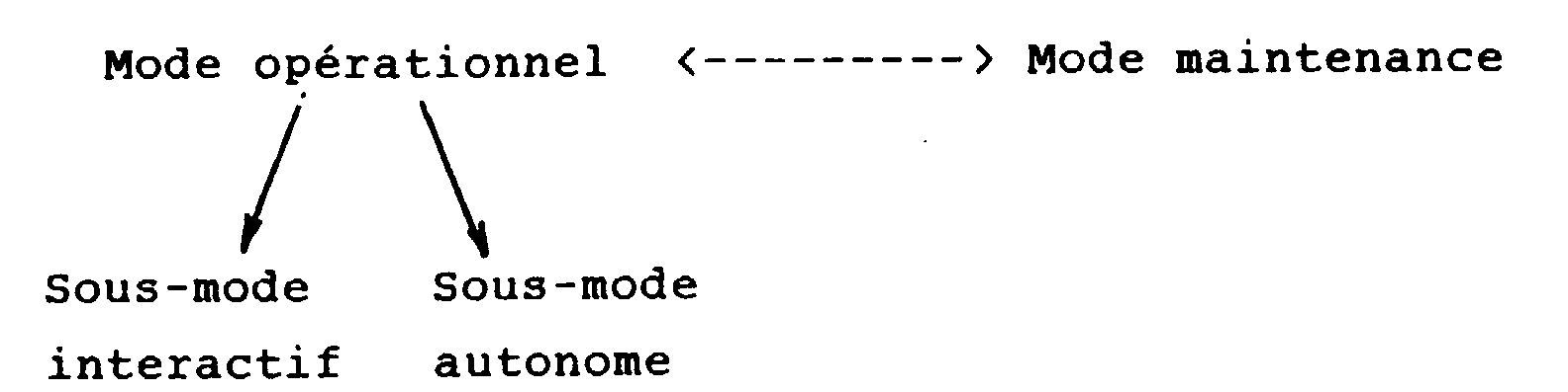
Elle supervise la mise en route et l'arrêt du sous-système. - Gestion des informations protégées.
La gestion de ces informations consiste à préserver leur validité dans toute circonstance en particulier au démarrage et à l'arrêt du sous-système.
Elles sont de deux types : - Les paramètres de fonctionnement.
L'origine absolue du convoyeur.
La composition du convoyeur.
Ces informations permettent d'être opérationnel rapidement. Elles sont donc vitales. - Les témoins d'usure.
Il s'agit de compteurs mis à la disposition du technicien de maintenance, car ils sont caractéristiques de la fatigue du du matériel.
Ces informations ne sont pas utiles au fonctionnement donc ne jouent pas sur la disponibilité du CHA.
Les informations d'entrée/sortie de la fonction automate de gestion sont les suivantes :- Flux d'informations n°1
- En entrée :
Paramètres associés aux ordres :- Type munition.
- Type de test.
- Etat sous-système ARME.
- Etat sous-système ASSERVISSEMENT.
- Etat sous-système MOYENS D'INSTRUCTION ET DE MAINTENANCE.
Acquittements alertes :- Convoyeur positionné.
- Refouloir positionné.
- Porte positionnée.
- Outillage verrouillé.
- Chambre canon vide.
- Fin de prise en charge manuelle.
- Arrêt d'urgence retiré.
Informations techniques.- Témoins d'usure (valeurs initiales).
- En sorties :
-

- Défauts.
- Etats de dégradation.
- Alertes opérateur.
- Informations techniques.
- Demande de site.
- En entrée :
- Flux d'information n°2
- En entrée :
Paramètres associés aux ordres :- Type munition.
- Type de test.
- Etat sous-système ARME
- Etat sous-système ASSERVISSEMENT
- Etat sous-système MOYENS D'INSTRUCTION ET DE MAINTENANCE.
Acquittements alertes :- Convoyeur positionné.
- Refouloir positionné.
- Porte positionnée.
- Outillage verrouillé.
- Chambre canon vide.
- Fin de prise en charge manuelle.
- Arrêt d'urgence retiré.
Informations techniques.- Témoins d'usure (valeurs initiales). Forçage :
- d'état des éléments fonctionnels,
- de valeur des E/S.
- En sorties :
-

- Défauts.
- Etats de dégradation.
- Alertes opérateur.
- Informations techniques.
- Demande de site.
- Valeurs logiques des E/S.
- En entrée :
- Flux d'information n° 3
- En entrée :
Il s'agit des ordres :- veille,
- sélection,
- chargement,
- test,
- approvisionnement,
- vidage.
En ordre de test, il y a des tests spécifiques à la maintenance par le canal OCSI qui ne sont pas utiles par le canal DIGIBUS. Il s'agit de mouvements élémentaires.
- En entrée :
- Flux d'information n° 4
- En entrée :
- . Alertes opérationnelles :
- . Demande d'intervention manuelle
- positionnement convoyeur.
- positionnement porte.
- positionnement refouloir.
- verrouillage de l'outillage.
- positionnement de l'alvéole 1 au poste d'approvisionnement.
- . Arme non vide
- . Arrêt d'urgence enclenché
- . Mode autonome en cours
- En sortie :
- . Acquittement des alertes :
- convoyeur positionné.
- porte positionnée.
- refouloir positionné.
- outillage verrouillé.
- fin de prise en charge manuelle.
- arme vide
- arrêt d'urgence retiré.
- . Acquittement des alertes :
- En entrée :
- Flux d'information n° 5
- En entrée :
- Compte rendu d'exécution.
- . séquence en cours,
- . anomalie de séquence.
- Annulation de séquence.
- Arrêt d'urgence.
- Mode en cours.
- Autorisation de mouvement.
- Compte rendu d'exécution.
- En sortie :
- Etat de dégradation des fonctions.
- Etats mécaniques courants :
- . convoyeur,
- . porte,
- . refouloir,
- . outillage,
- . manivelle.
- En entrée :
- Flux d'information n° 6
- En entrée :
- Données présentes en mémoire permanente
- En sortie :
- Données à sauvegarder en mémoire permanente.
- En entrée :
- Flux d'information n° 7
Ce flux d'informations transite vers la carte coupleur DIGIBUS 51 et la liaison 60 ( Fig.3).- En entrée :
- . Messages émis par la conduite de tir.
- commande de transfert
- commande de voie
- commande de test
- message de service
- n° de cycle court
- message de commande du CHA
- . Messages d'acquisition du sous-système armé.
- . Messages de mode du sous-système asservissement
- . Messages techniques du sous-système moyens d'instruction et de maintenance.
- . Messages émis par la conduite de tir.
- En sortie :
- Message de mode sous-système CHA.
- Message d'état sous-système CHA.
- Message technique sous-système CHA.
- Message de test (commande de test).
- En entrée :
- Flux d'information n° 8
Ce flux d'informations transite à travers la carte unité centrale 56 par lescircuits 74 et 75 de la Fig.4.- En entrée :
- Code touche (écran tactile).
- Code arme.
- Présence du coffret OCSI.
- En sortie :
- Message de mode sous-système CHA.
- Message d'état sous-système CHA.
- Message technique sous-système CHA.
- Menu opérateur et visualisation.
- Voyant chien de garde.
Le pilotage du CHA peut s'effectuer par les canaux DIGIBUS et OCSI séparément, sachant que la présence à la mise sous tension de ce dernier implique l'impossibilité d'utiliser le premier. - Canal DIGIBUS.
Le CHA est un abonné sur DIGIBUS.
La réception des messages est cadencée par le gérant du BUS. Du fait de la répétition du même message à intervalles réguliers, le sous-système ne réagit qu'aux variations du message entre deux périodes.
Chaque nouveau message est décodé et ses informations sont traduites en données exploitables par toutes les fonctions.
En émission, le message est formaté puis mis à jour dans la zone d'échange du coupleur DIGIBUS. Le prélèvement est cadencé lui aussi par le gérant du bus. - Canal OCSI.
L'opérateur dispose de menus déroulants sur l'écran tactile. Il peut émettre des ordres, visualiser, modifier des données sous-systèmes, saisir/exécuter un programme, contrôler l'enchaînement des menus, lire des messages d'états qui apparaissent au fil de l'eau. La gestion de l'écran est faite compte tenu des chaînes de caractères saisies et du fonctionnement courant du CHA. Les informations liées à l'ARME transitent elles aussi par le même canal.Il s'agit de l'état de la culasse et du site de chargement. - Supervision du sous-système.
- En entrée :
Cette supervision assure les processus suivants :- Processus de gestion des ordres.
- Il gère la réception des ordres.
- Il conditionne leur exécution.
- Il contrôle la cohérence de l'état mécanique.
- Il transmet l'ordre aux fonctions qui ont la charge de l'exploiter :
- . fonction SELECTION,
- . fonction CHARGEMENT,
- . fonction PROTECTION,
- . fonction APPROVISIONNEMENT/VIDAGE
- Il gère les chiens de garde du sous-système dont le rôle est de garantir sa sécurité en cas de fonctionnement aberrant.
- Il annule si nécessaire l'ordre en cours.
- Processus de gestion des acquittements.
Il construit les messages qui sont émis vers les processus de dialogue DIGIBUS et OCSI et effectue la gestion des acquittements. Dans ce cas, la fonction émettrice d'une demande d'intervention est mise en attente de cet acquittement. Cette attente peut être interrompue ou non par un changement d'ordre. Dès réception de l'acquittement, la fonction reprend son traitement suspendu. - Processus de gestion de la mémoire permanente (carte-mémoire 52 - Fig.3).
A la mise sous tension, ce processus est chargé de récupérer les informations ou paramètres de fonctionnement utiles ou nécessaires au CHA, en particulier :- L'origine codeur, car elle conditionne le positionnement du convoyeur à l'arrêt au cycle.
- La composition du convoyeur car sa cohérence permet la sélection d'une munition dans le plus bref délai.
- Les témoins (indicateurs) d'usure.
Lors de la disparition du réseau de bord ou de la mise à l'état panne du CHA, ces données sont placées dans la mémoire permanente du sous-système.
On va maintenant exposer quelques remarques relaties aux performances dans les traitements et situations de fonctionnement. - Traitement DIGIBUS : Le temps de traitement des informations DIGIBUS est dans tous les cas strictement inférieur à 100 ms.
Le processus qui le gère garantit la prise en compte de tous les messages qui intéressent le CHA, en particulier lorsque ceux-ci arrivent dans la même période de la trame DIGIBUS, sachant que cette situation ne peut arriver au pire que toutes les 100 ms.
Lorsque DIGIBUS envoie un ordre, le CHA indique à la CDT que celui-ci est acquis dans un délai inférieur ou égal à 100 ms. Toutefois, il existe pour le CHA un temps de mise en oeuvre de cet ordre qui dépend de son environnement. - Si le sous-système est en attente et dans un état mécanique cohérent, le temps de mise à exécution est inférieur ou égal à 200 ms.
- Si le sous-système est en cours d'éxécution d'ordre, le temps de réaction est lié au contexte d'annulation, il est toutefois inférieur ou égal à 3s.
- Si le sous-système est dans un état mécanique incohérent, le délai est lié à l'opérateur char-gé de remettre le CHA dans un état conforme avant toute exécution d'ordre.
- Flux d'informations n°1
- Traitement OCSI.
Les informations ARME qui transitent par le coffret OCSI sont traitées en un temps inférieur ou égal à 20 ms. Le temps de transfert du coffret OCSI vers le calculateur 13 est inférieur ou égal à 10 ms. - Arrêt d'urgence.
Le temps réponse du sous-système suite à une action sur coup de poing d'arrêt d'urgence est inférieur ou égal à 150 ms. Ce temps garantit l'arrêt de mouvement mécanique.
Le compte rendu du sous-système à l'attention de l'opérateur est inférieur ou égal à 1 s. - Temps d'initialisation.
Dans la mesure où l'état mécanique du CHA à la mise sous tension ne requiert pas l'aide de l'opérateur (action manuelle), l'initialisation totale comprenant le test, jusqu'à la phase d'attente d'ordre, est inférieur ou égal à 5 s. - Temps d'arrêt.
Il est fonction des technologies employées. Celle retenue pour le CHA garantit une sauvegarde en 10 ms.
On va maintenant considérer la disponibilité et le fonctionnement dégradé de la fonction automate de gestion. - Etat mécanique.
L'exécution d'un ordre est retardée si l'état mécanique du sous-système n'est pas connu.
La fonction procède avant l'exécution de l'ordre à une initialisation mécanique préalable. - Prise en charge manuelle.
La prise en charge manuelle par l'opérateur est prépondérante sur l'automatisme. Si une manivelle est enclenchée au cours d'une opération, celle-ci est suspendue. L'arrêt de l'opération est immédiat si c'est le convoyeur qui est en mouvement. Dans le cas d'un mouvement du refouloir ou de la porte, l'arrêt de l'opération a lieu à la fin du mouvement en cours.
Dès la disparition de la prise en charge manuelle, l'opération suspendue reprend son cours après une phase d'initialisation telle que décrite ci-dessus et si aucun nouvel ordre n'a été commandé par la conduite de tir. - Arrêt d'urgence.
On distingue l'arrêt d'urgence issu d'une anomalie logiciel, de celui issu du coup de poing d'arrêt d'urgence.- l'arrêt d'urgence logiciel conduit quel que soit l'état du CHA, à une situation bloquante qui interdit tous échanges avec l'extérieur; seule une remise sous tension peut l'en sortir,
- l'arrêt d'urgence matériel procède de la même manière que pour la prise en charge manuelle.
- Paramètre de fonctionnement.
La perte de l'origine codeur conduit à une indisponibilité totale du CHA dans le cadre de sa mission opérationnelle. Toutefois, cette situation n'interdit pas les tests internes n'impliquent pas de mouvement.
La perte de la composition convoyeur conduit la fonction sélection à effectuer une reconfiguration qui augmente le temps d'exécution de l'ordre de sélection. Si on aboutit à une reconfiguration impossible du fait de la dégradation de la mémoire permanente, le sous-système indique qu'il est inopérant ce qui signifie qu'il ne peut remplir sa mission opérationnelle. Toutefois, cette situation n'interdit aucun test interne.
Les opérations particulières de la fonction sont les suivantes : - Les commandes à bras.
Si l'opérateur enclenche les commandes à bras sans y avoir été invité par le CHA, la fonction automate provoque en conséquence : - une annulation de séquence,
- un blocage des ordres,
- un blocage des mouvements mécaniques, jusqu'à ce que l'opérateur indique explicitement la fin de sa manoeuvre manuelle.
- Coupure et mise sous tension.
La fonction procède à la mise sous tension à un auto-test interne statique (sans mouvement mécanique) permettant d'informer l'opérateur de son état de disponibilité. Elle procède à l'initialisation du dialogue sous-système en particulier au transfert d'informations de sa mémoire permanente en direction de la conduite de tir. Elle effectue l'initialisation mécanique des fonctions et se place dans un état d'attente d'ordre.
A la disparition du réseau de bord, la fonction met en oeuvre une opération de sauvegarde des informations vitales dans la mémoire permanente et évalue la signature qui garantit la cohérence de ces informtions lors de la remise sous tension. - Veille de batterie.
La présence de cette information issue du sous-système DE MOYENS D'INSTRUCTION ET DE MAINTENANCE entraîne la fonction dans un processus de blocage des mouvements mécaniques. Aucun ordre n'est exécutable, aucun voyant n'est allumé jusqu'à la disparition de cette information. - Connexion/déconnexion DIGIBUS.
Le dialogue n'est possible que lorsque le sous-système est connecté. - Silence bus.
Lorsque le sous-système est connecté comme indiqué ci-dessus, la fonction surveille l'évolution périodique du N° de cycle court (NCC) qui transite sur la trame DIGIBUS toutes les 10 ms. Une absence de message ou une non évolution du numéro de cycle court pendant onze cycles à 100 Hz, caractérise un " silence bus " et dans ce cas, la foncion adopte un mode de fonctionnement autonome. Par opposition à un mode de fonction interactif via DIGIBUS ou OCSI, le mode autonome implique le pilotage du CHA à travers un coffret d'approvisionnement externe aux seules fins de mise en oeuvre d'un approvisionnement/vidage externe réalisé par la fonction du même nom. Dans ce mode, le Dialogue est réduit, il n'y a pas de fonctionnement dégradé possible. Le sous-système sort de cet état dès que la conduite de tir connecte à nouveau le CHA au DIGIBUS et si aucun ordre d'approvisionnement ou de vidage est en cours. - Erreur bus.
La fonction est chargée de surveiller les erreurs de transmission dans les échanges DIGIBUS. Elle renseigne l'opérateur sur le nombre d'erreurs qu'elle détecte à chaque minute.
On va décrire l'architecture fonctionnelle intermédiaire dont est issue l'architecture physique du dispositif suivant l'invention déjà décrit en référence aux Fig.1 à 7B.
On distingue les éléments :- CONVOYEUR : mécanisme 5 de transport de munition à moteur électrique 7 (magasin).
- REFOULOIR : mécanisme 9 de transfert de munitions à moteur électrique 11.
- PORTE : mécanisme de
protection 14 à moteur électrique 16. - BECAL : coffret calculteur 13 chargé de piloter les mécanismes en utilisant capteurs et actionneurs, sous la tutelle des canaux OCSI et DIGIBUS.
- BECMO : coffret de commande 8 chargé de piloter les moteurs qui équipent la porte, le refouloir et le covoyeur.
- BEAPE :
interface 17 de dialogue opérateur pour l'approvisionnement/vidage externe. - DAMIE : dispositif 21 (Fig.1) d'extraction et d'insertion d'une munition dans une alvéole convoyeur.
- BECHV : capteur 36 (Fig.2) destiné à évaluer l'état de vacuité du chemin de chargement.
- BEIMD, BEIMG : capteurs redondants 30,31 (Fig.2) chargés de lire les codes barres de munition.
- FCPMC : capteur 12 (Fig.2) chargé de garantir la présence de munition au poste de chargement, lors d'un refoulement.
- Capteurs divers (non représentés) :
- BECOD : codeur absolu 19 (Fig.2) de position convoyeur.
- FCPFE, FCPOU : capteur 34,35 (Fig.2) d'état porte ouverte/fermée.
- FCRRE : capteur 27 (Fig.2) d'état refouloir rentré.
- FCORE : capteur 28 (Fig.2) d'état outillage verrouillé. On constate que :
- DIGIBUS est un canal sur lequel sont raccordés les sous-systèmes AMA, ASS, TBP, CDT.
- Les SERVITUDES occupent deux réseaux, l'un pour BECAL, l'autre pour BECMO afin d'isoler les éléments de puissance des éléments de commande.
La répartition organique des fonctions est la suivante:- Fonction sélection.
Elle met en oeuvre le calculateur BECAL 13 qui reçoit l'ordre de sélection par le canal OCSI ou DIGIBUS. Celui-ci commande l'interface de puissance BECMO 8 chargé d'actionner la motorisation duCONVOYEUR 5. La séquence ou algorithme de positionnement du CONVOYEUR est exécutée par le calculateur 13 au moyen des capteurs deposition BECOD 19 et d'identifiction BEIMD, BEIMG,FCPMC
La commande manuelle de cette fonction est réalisée par l'opérateur via un moteur auxiliaire qui équipe le convoyeur. Lors des séquences automatiques, les interventions manuelles de l'opérateur sont demandées par le calculateur 13. - Fonction chargement.
Elle met en oeuvre le calculateur BECAL 13 qui reçoit l'ordre de chargement par le canal OCSI ou DIGIBUS. Celui-ci commande l'interface de puissance BECMO 8 chargé d'actionner la motorisation 11 duREFOULOIR 9.
La séquence ou algorithme de rentrée ou de sortie du refouloir 9 est exécutée par le calculateur au moyen de capteurs FCRRE,BECHV 27, 36 et d'informations BECMO et sous-système AMA et ASS. Les mouvements manuels du REFOULOIR sont conditionnés et mis en oeuvre de la même façon que pour le CONVOYEUR. - Fonction protection.
Elle met en oeuvre le calculateur BECAL 13 qui, si nécesaire, commande l'interface de puissance BECMO 8 chargé d'actionner la motorisation de laporte 14.
Elle peut être sollicitée par la fonction chargement précédemment décrite.
La séquence ou algorithme d'ouverture ou de fermeture de la porte est exécutée par le calculateur au moyen des capteurs FCPFE, FCPOU 34,35.
Le capteur "chambre vide "BECHV 36 est monté physiquement sur laporte 14 car elle est située dans l'axe de refoulement. - Fonction approvisionnement/vidage.
Elle utilise la fonction sélection lorsqu'il est nécessaire d'effectuer une rotation du CONVOYEUR. Elle met en oeuvre par ailleurs le calculateur BECAL qui reçoit l'ordre d'approvisionnement/vidage par les canaux DIGIBUS et OCSI ou (en mode autonome) par le coffret BEAPE 26 (Fig.2).
Ce calculateur déroule l'algorithme correspondant, sous le contrôle de l'opérateur qui dispose comme interface de dialogue. - en opération externe : du coffret BEAPE 26
- en opération interne : des consoles opérateur OCSI DIGIBUS
Le dispositif d'approvisionnement/vidage manuel DAMIE est réversible pour permettre un usage en interne comme en externe. Il est équipé du capteur FCORE 28 dont l'état est exploité par le calculateur. L'identification des munitions ou l'état des alvéoles sont donnés par les capteur BEIMD, BEIMG,FCPMC - Fonction automate de gestion.
Elle est remplie par le calculateur 13. Il constitue l'élément de commande centrale de l'automatisme chargement automatique, il est en particulier chargé de gérer la communication avec les autres sous-systèmes, d'assurer la sécurité du CHA, de préserver ces paramètres de fonctionnement, d'accepter ou non l'exécution d'ordre venant de l'opérateur.
Le logiciel implanté dans le calculateur BECAL a pour mission au travers de son environnement matériel :- 1) de réaliser l'interface de dialogue DIGIBUS, de réaliser l'interface de dialogue OCSI.
- 2) de réaliser le positionnement des mecanismes : - REFOULOIR, CONVOYEUR, PORTE.
- 3) d'assurer la sécurité du sous-système,
- 4) d'effectuer l'auto-diagnostic du sous-système,
- 5) d'éxécuter les séquences relatives aux ordres, dans une situation de fonction nominale ou dégradée.
En particulier :- la veille,
- la sélection,
- le chargement,
- l'approvisionnement,
- le vidage,
- les tests déclenchés automatiques ou manuels.
- Management of the DIGIBUS dialog interface.
It ensures the logical and physical transfer of information from the CHA to the other subsystems, in particular to the fire control. It also ensures the transfer and processing of all the information from the other subsystems which condition the functioning of the CHA. - Management of the OCSI dialog interface.
Taken in isolation, CHA can be implemented in the absence of DIGIBUS. This interface manages an alphanumeric terminal with a touch screen. In particular, it performs menu management, their presentation and the formatting of various information of interest to the operator. - Management of alerts and acknowledgment.
It consists of processing alerts following faults that the other functions have detected (degradations) and verifying the operator's acknowledgments following manual interventions requested by the other functions. - Order management and security.
It ensures the consistency of orders and their execution according to the current situation of the CHA. It is responsible for ensuring the safety of personnel (handling of emergency stops).
The orders, after filtering, are transmitted to the other functions. It ensures the passage from one mode to another.
It supervises the starting and stopping of the subsystem. - Management of protected information.
The management of this information consists in preserving its validity in all circumstances, in particular when starting and stopping the subsystem.
There are two types: - The operating parameters.
The absolute origin of the conveyor.
The composition of the conveyor.
This information allows you to be operational quickly. They are therefore vital. - The wear indicators.
These are meters made available to the maintenance technician, as they are characteristic of the fatigue of the equipment.
This information is not useful for operation and therefore does not affect the availability of the CHA.
The input / output information of the management PLC function is as follows:- Information flow n ° 1
- Entrance :
Parameters associated with orders:- Ammunition type.
- Type of test.
- WEAPON subsystem status.
- SERVO subsystem state.
- INSTRUCTION AND MAINTENANCE SUB-SYSTEM STATE.
Acknowledgments:- Positioned conveyor.
- Repressor positioned.
- Door positioned.
- Tool locked.
- Empty barrel chamber.
- End of manual care.
- Emergency stop removed.
Technical informations.- Wear indicators (initial values).
- Outings:
-
- Defaults.
- States of degradation.
- Operator alerts.
- Technical informations.
- Site request.
- Entrance :
- Information flow n ° 2
- Entrance :
Parameters associated with orders:- Ammunition type.
- Type of test.
- WEAPON subsystem status
- SERVO subsystem status
- INSTRUCTION AND MAINTENANCE SUB-SYSTEM STATE.
Acknowledgments:- Positioned conveyor.
- Repressor positioned.
- Door positioned.
- Tool locked.
- Empty barrel chamber.
- End of manual care.
- Emergency stop removed.
Technical informations.- Wear indicators (initial values). Forcing:
- state of the functional elements,
- value of I / O.
- Outings:
-
- Defaults.
- States of degradation.
- Operator alerts.
- Technical informations.
- Site request.
- Logical I / O values.
- Entrance :
- Information flow n ° 3
- Entrance :
These are orders:- standby,
- selection,
- loading,
- test,
- supply,
- emptying.
In test order, there are specific maintenance tests by the OCSI channel which are not useful by the DIGIBUS channel. These are elementary movements.
- Entrance :
- Information flow n ° 4
- Entrance :
- . Operational alerts:
- . Manual intervention request
- conveyor positioning.
- door positioning.
- repressor positioning.
- tool lock.
- positioning of
cell 1 at the supply station.
- . Non-empty weapon
- . Emergency stop engaged
- . Autonomous mode in progress
- Output :
- . Acknowledgment of alerts:
- positioned conveyor.
- door positioned.
- repressor positioned.
- tool locked.
- end of manual care.
- empty weapon
- emergency stop removed.
- . Acknowledgment of alerts:
- Entrance :
- Information flow n ° 5
- Entrance :
- Execution report.
- . current sequence,
- . sequence anomaly.
- Sequence cancellation.
- Emergency stop.
- Current mode.
- Movement authorization.
- Execution report.
- Output :
- State of degradation of functions.
- Common mechanical states:
- . conveyor,
- . door,
- . push back,
- . tools,
- . crank.
- Entrance :
- Information flow n ° 6
- Entrance :
- Data in permanent memory
- Output :
- Data to be saved in permanent memory.
- Entrance :
- Information flow n ° 7
This information flow passes to theDIGIBUS coupler card 51 and the link 60 (Fig. 3).- Entrance :
- . Messages issued by the fire control.
- transfer order
- channel control
- test command
- service message
- short cycle number
- CHA command message
- . Armed subsystem acquisition messages.
- . Control subsystem mode messages
- . Technical messages from the means of instruction and maintenance subsystem.
- . Messages issued by the fire control.
- Output :
- CHA subsystem mode message.
- CHA subsystem status message.
- Technical message CHA subsystem.
- Test message (test command).
- Entrance :
- Information flow n ° 8
This flow of information passes through thecentral unit card 56 through thecircuits - Entrance :
- Key code (touch screen).
- Weapon code.
- Presence of the OCSI box.
- Output :
- CHA subsystem mode message.
- CHA subsystem status message.
- Technical message CHA subsystem.
- Operator menu and display.
- Seeing watchdog.
The control of the CHA can be done through the DIGIBUS and OCSI channels separately, knowing that the presence when the latter is powered up means that the former cannot be used. - DIGIBUS channel.
The CHA is a subscriber to DIGIBUS.
The reception of messages is clocked by the BUS manager. Due to the repetition of the same message at regular intervals, the subsystem only reacts to variations in the message between two periods.
Each new message is decoded and its information is translated into data usable by all functions.
On transmission, the message is formatted and then updated in the exchange area of the DIGIBUS coupler. The pickup is also clocked by the bus manager. - OCSI channel.
The operator has drop-down menus on the touch screen. It can issue orders, view, modify subsystem data, enter / execute a program, control the flow of menus, read status messages that appear over time. The screen is managed taking into account the character strings entered and the current operation of the CHA. Information related to the WEAPON also passes through the same channel: the state of the breech and the loading site. - Subsystem supervision.
- Entrance :
This supervision ensures the following processes:- Order management process.
- He manages the reception of orders.
- It conditions their execution.
- It checks the consistency of the mechanical state.
- It transmits the order to the functions responsible for using it:
- . SELECTION function,
- . LOADING function,
- . PROTECTION function,
- . SUPPLY / EMPTYING function
- It manages the watchdogs of the subsystem whose role is to guarantee its security in the event of aberrant operation.
- It cancels the current order if necessary.
- Acknowledgment management process.
It builds the messages that are sent to the DIGIBUS and OCSI dialog processes and performs the acknowledgment management. In this case, the function issuing an intervention request is put on hold for this acknowledgment. This wait can be interrupted or not by a change of order. Upon receipt of the acknowledgment, the function resumes its suspended processing. - Permanent memory management process (memory card 52 - Fig. 3).
On power-up, this process is responsible for retrieving the information or operating parameters useful or necessary for the CHA, in particular:- The encoder origin, because it conditions the positioning of the conveyor at the cycle stop.
- The composition of the conveyor because its consistency allows the selection of ammunition in the shortest possible time.
- The wear indicators.
When the on-board network disappears or the CHA goes into fault mode, this data is placed in the permanent memory of the subsystem.
We will now set out some remarks relating to performance in processing and operating situations. - DIGIBUS processing: The processing time for DIGIBUS information is in all cases strictly less than 100 ms.
The process that manages it ensures that all messages of interest to the CHA are taken into account, in particular when these arrive in the same period of the DIGIBUS frame, knowing that this situation can only happen at worst every 100 ms.
When DIGIBUS sends an order, the CHA indicates to the CDT that it is acquired within a time less than or equal to 100 ms. However, there is a time for implementation of this order for the CHA which depends on its environment. - If the subsystem is on standby and in a coherent mechanical state, the execution time is less than or equal to 200 ms.
- If the subsystem is executing an order, the reaction time is linked to the cancellation context, it is however less than or equal to 3s.
- If the subsystem is in an inconsistent mechanical state, the delay is linked to the operator responsible for returning the CHA to a compliant state before any order execution.
- Information flow n ° 1
- OCSI processing.
The WEAPON information which passes through the OCSI controller is processed in a time less than or equal to 20 ms. The transfer time from the OCSI box to thecomputer 13 is less than or equal to 10 ms. - Emergency stop.
The response time of the subsystem following an emergency stop punch action is less than or equal to 150 ms. This time guarantees the mechanical movement stop.
The subsystem report to the operator is less than or equal to 1 s. - Initialization time.
Insofar as the mechanical state of the CHA at power-up does not require the assistance of the operator (manual action), the total initialization including the test, until the order waiting phase, is less than or equal to 5 s. - Break time.
It depends on the technologies used. The one selected for the CHA guarantees a backup in 10 ms.
We will now consider the availability and degraded operation of the management PLC function. - Mechanical condition.
The execution of an order is delayed if the mechanical state of the subsystem is not known.
The function proceeds before the execution of the order to a preliminary mechanical initialization. - Manual support.
Manual management by the operator is paramount over the automation. If a crank is engaged during an operation, it is suspended. The operation is stopped immediately if the conveyor is in motion. In the case of a movement of the repressor or of the door, the operation stops at the end of the movement in progress.
As soon as manual support has disappeared, the suspended operation resumes its course after an initialization phase as described above and if no new order has been ordered by the fire control. - Emergency stop.
A distinction is made between the emergency stop resulting from a software anomaly and that resulting from the emergency stop punch.- the software emergency stop leads, whatever the state of the CHA, to a blocking situation which prohibits all exchanges with the outside; only one power on can get out of it,
- the hardware emergency stop proceeds in the same way as for manual handling.
- Operating parameter.
The loss of the encoder origin leads to a total unavailability of the CHA as part of its operational mission. However, this situation does not prohibit internal tests do not involve movement.
The loss of the conveyor composition leads the selection function to perform a reconfiguration which increases the execution time of the selection order. If an reconfiguration is impossible due to the degradation of the permanent memory, the subsystem indicates that it is inoperative, which means that it cannot fulfill its operational mission. However, this situation does not prohibit any internal testing.
The specific operations of the function are as follows: - Hand controls.
If the operator engages the arm controls without being asked to do so by the CHA, the PLC function consequently causes: - sequence cancellation,
- blocking of orders,
- a blocking of mechanical movements, until the operator explicitly indicates the end of his manual operation.
- Cut and power up.
The function powers up a static internal self-test (without mechanical movement) to inform the operator of its availability status. It initializes the subsystem dialogue, in particular the transfer of information from its permanent memory to the fire control. It performs the mechanical initialization of the functions and places itself in a state of waiting for order.
When the on-board network disappears, the function implements an operation to save vital information in the permanent memory and evaluates the signature which guarantees the consistency of this information when power is restored. - Battery standby.
The presence of this information from the INSTRUCTION AND MAINTENANCE MEANS subsystem involves the function in a process of blocking mechanical movements. No order can be executed, no indicator light is on until this information disappears. - DIGIBUS connection / disconnection.
Dialog is only possible when the subsystem is connected. - Bus silence.
When the subsystem is connected as indicated above, the function monitors the periodic evolution of the short cycle number (NCC) which passes on the DIGIBUS frame every 10 ms. An absence of message or a non-evolution of the short cycle number for eleven cycles at 100 Hz, characterizes a "bus silence" and in this case, the function adopts an autonomous operating mode. In contrast to an interactive function mode via DIGIBUS or OCSI, the autonomous mode involves controlling the CHA through an external supply unit for the sole purpose of implementing external supply / emptying performed by the function of the same name . In this mode, the Dialogue is reduced, there is no degraded operation possible. The subsystem exits from this state as soon as the firing line again connects the CHA to the DIGIBUS and if no supply or emptying order is in progress. - Bus error.
The function is responsible for monitoring transmission errors in DIGIBUS exchanges. It informs the operator of the number of errors it detects every minute.
We will describe the intermediate functional architecture from which comes the physical architecture of the device according to the invention already described with reference to Fig.1 to 7B.
We distinguish the elements:- CONVEYOR:
mechanism 5 for transporting ammunition with electric motor 7 (magazine). - REFOULOIR:
mechanism 9 for transferring ammunition withelectric motor 11. - DOOR:
protection mechanism 14 withelectric motor 16. - BECAL: 13 calculator box responsible for controlling the mechanisms using sensors and actuators, under the supervision of the OCSI and DIGIBUS channels.
- BECMO:
control box 8 responsible for controlling the motors fitted to the door, the pressure ram and the conveyor. - BEAPE:
operator dialogue interface 17 for external supply / emptying. - DAMIE: device 21 (Fig. 1) for extracting and inserting ammunition into a conveyor cell.
- BECHV: sensor 36 (Fig. 2) intended to assess the emptiness of the loading path.
- BEIMD, BEIMG: 30.31 redundant sensors (Fig. 2) responsible for reading ammunition bar codes.
- FCPMC: sensor 12 (Fig. 2) responsible for ensuring the presence of ammunition at the loading station, during delivery.
- CONVEYOR:
- Various sensors (not shown):
- BECOD: absolute encoder 19 (Fig. 2) of conveyor position.
- FCPFE, FCPOU: door open / closed state sensor 34.35 (Fig. 2).
- FCRRE: sensor 27 (Fig. 2) reentry state returned.
- FCORE: sensor 28 (tool locked condition). We observe that :
- DIGIBUS is a channel to which the AMA, ASS, TBP, CDT subsystems are connected.
- SERVITUDES occupy two networks, one for BECAL, the other for BECMO in order to isolate the power elements from the control elements.
The organic distribution of functions is as follows:- Selection function.
It implements theBECAL 13 computer which receives the selection order via the OCSI or DIGIBUS channel. This controls theBECMO 8 power interface responsible for actuating theCONVEYOR 5 motorization. The positioning sequence or algorithm of the CONVEYOR is executed by thecomputer 13 by means of the position sensors BECOD 19 and of identification BEIMD, BEIMG,FCPMC
The manual control of this function is carried out by the operator via an auxiliary motor which equips the conveyor. During the automatic sequences, the manual interventions of the operator are requested by thecomputer 13. - Load function.
It implements theBECAL 13 computer which receives the loading order via the OCSI or DIGIBUS channel. This controls theBECMO power interface 8 responsible for actuating the motorization of theREFOULOIR 9.
The re-entry or exit sequence or algorithm of therepressor 9 is executed by the computer using FCRRE,BECHV 27, 36 sensors and BECMO information and the AMA and ASS subsystem. The manual movements of the REFOULOIR are conditioned and implemented in the same way as for the CONVEYOR. - Protection function.
It implements theBECAL 13 computer which, if necessary, controls theBECMO 8 power interface responsible for actuating the motorization ofdoor 14.
It can be requested by the loading function described above.
The door opening or closing sequence or algorithm is executed by the computer by means of the FCPFE, FCPOU 34.35 sensors.
TheBECHV 36 "empty chamber" sensor is physically mounted on thedoor 14 because it is located in the delivery axis. - Supply / emptying function.
It uses the selection function when it is necessary to rotate the CONVEYOR. It also implements the BECAL computer which receives the supply / emptying order via the DIGIBUS and OCSI channels or (in stand-alone mode) through theBEAPE 26 box (Fig. 2).
This computer runs the corresponding algorithm, under the control of the operator who has a dialog interface. - in external operation: from the
BEAPE 26 box - in internal operation: OCSI DIGIBUS operator consoles
The DAMIE manual supply / emptying device is reversible to allow internal and external use. It is equipped with the FCORE 28 sensor, the status of which is used by the computer. The identification of the ammunition or the state of the cells are given by the BEIMD, BEIMG,FCPMC - PLC management function.
It is filled by thecomputer 13. It constitutes the central control element of the automatic loading automation, it is in particular responsible for managing communication with the other subsystems, ensuring the safety of the CHA, preserving these operating parameters, to accept or not the execution of orders from the operator.
The mission of the software installed in the BECAL calculator is through its hardware environment:- 1) realize the DIGIBUS dialog interface, realize the OCSI dialog interface.
- 2) to carry out the positioning of the mechanisms: - REFOULOIR, CONVEYOR, DOOR.
- 3) ensure the security of the subsystem,
- 4) to carry out the self-diagnosis of the subsystem,
- 5) to execute the sequences relating to orders, in a nominal or degraded function situation.
In particular :- the day before,
- the selection,
- the loading,
- supply,
- emptying,
- automatic or manual triggered tests.
On va examiner les modes interne de fonctionnement du dispositif.We will examine the internal modes of operation of the device.
Il s'agit des modes suivants :These are the following modes:
Le mode normal caractérise le fonctionnement nominal du CHA. Il implique une disponibilité totale et des performances non dégradées du sous-système.Normal mode characterizes the nominal operation of the CHA. It implies total availability and undegraded performance of the subsystem.
Le mode dégradé caractérise le fonctionnement non nominal du CHA. Il indique que le sous-système est incapable d'accomplir sa mission sans intervention humaine. Ce mode est dit aussi semi-automatique ou manuel. Le sous-système possède des performances plus ou moins dégradées.The degraded mode characterizes the non-nominal operation of the CHA. It indicates that the subsystem is unable to accomplish its mission without human intervention. This mode is also called semi-automatic or manual. The subsystem has more or less degraded performance.
Le mode opérationnel matérialise le contexte dans lequel le CHA garantit sa capacité à traiter tous les ordres prévus lors d'une mise en oeuvre opérationnelle. le mode de maintenance est celui dans lequel le CHA exécute les ordres réservés à la maintenance du sous-système. Il s'agit de localiser les éléments fonctionnels en panne qui caractérisent un fonctionnement dégradé.The operational mode materializes the context in which the CHA guarantees its capacity to process all the orders provided during an operational implementation. the maintenance mode is that in which the CHA executes the orders reserved for the maintenance of the subsystem. This involves locating the functional elements which have broken down and which characterize degraded operation.
Le mode lancement est celui dans lequel le sous-système se place à la mise sous tension pour indiquer qu'il est dans une phase d'initialisation matérielle et logicielle.The launch mode is that in which the subsystem places itself at power-up to indicate that it is in a hardware and software initialization phase.
Le mode interactif est le mode de fonctionnement usuel du CHA caractérisé par l'intéractivité des échanges entre le sous-système et son environnement.The interactive mode is the usual operating mode of the CHA characterized by the interactivity of the exchanges between the subsystem and its environment.
Dans ce mode toutes les possibilités d'utilisation du CHA peuvent être mises en oeuvre.In this mode all the possibilities of using the CHA can be implemented.
Le mode autonome est celui dans lequel se confine le CHA en cas de silence BUS (anomalie particulière DIGIBUS). Seules les opérations d'approvisionnement/vidage en externe sont réalisables. La disparition du silence BUS conduit le sous-système à reprendre un mode de fonctionnement interactif dès que l'opération en cours est terminée.The autonomous mode is that in which the CHA confines itself in the event of BUS silence (particular DIGIBUS anomaly). Only external supply / dump operations are possible. The disappearance of the BUS silence leads the subsystem to resume an interactive operating mode as soon as the current operation is completed.
Le mode automatique est le mode d'utilisation qui nécessite le fonctionnement de l'automate (gestion automatique du CHA et de ses mouvements).The automatic mode is the mode of use which requires the functioning of the automaton (automatic management of the CHA and its movements).
Le mode manuel est le mode dont l'opérateur dispose par défaut si le sous-système est hors tension ou en panne. Si le sous-système est en fonctionnement automatique, l'opérateur impose le mode manuel, par une prise en charge des commandes à bras (manivelles 22,23, Fig.1).Manual mode is the mode available to the operator by default if the subsystem is powered down or has failed. If the subsystem is in automatic operation, the operator imposes manual mode, by taking over the arm controls (cranks 22,23, Fig.1).
Le CHA dans ces conditions reste sous tension mais n'assure plus de surveillance ni gestion (l'opérateur utilise le CHA à sa guise). C'est en règle générale l'attitude adoptée en cas de panne grave ou d'indisponibilité totale.The CHA under these conditions remains energized but no longer provides monitoring or management (the operator uses the CHA as it pleases). It's in as a general rule, the attitude adopted in the event of a serious breakdown or total unavailability.
On dit que le CHA est en panne lorsqu'il est totalement indisponible. Toutefois, on considère aussi que le sous-système est en panne s'il n'admet plus qu'un fonctionnement en manuel.It is said that the CHA is broken down when it is completely unavailable. However, it is also considered that the subsystem has failed if it only accepts manual operation.
Dans la mesure où la fonction automate de gestion est en état de marche, le sous-système malgré l'état de panne dans lequel il peut être, permet l'éxécution des tests déclenchés nécessaires à sa maintenance.Insofar as the management PLC function is in working order, the subsystem, despite the fault state in which it may be, allows the execution of the triggered tests necessary for its maintenance.
Si l'opérateur indique une fin de prise en charge manuelle, le CHA revient à un mode de fonctionnement automatique.If the operator indicates that manual care has ended, the CHA returns to an automatic operating mode.
L'interface opérateur-char utilise l'interface fonctionnel DIGIBUS 41 qui sera décrit par la suite.The operator-char interface uses the
Le message de commande est issu de la conduite de TIR par laquelle transitent les ordres et les acquittements de l'opérateur.The command message comes from the conduct of TIR through which the operator's orders and acknowledgments pass.
Au dispositif est de plus associée une interface destinée à un opérateur en atelier en vue d'assurer le contrôle ou la maintenance du dispositif.The device is also associated with an interface intended for a workshop operator in order to ensure the control or maintenance of the device.
Dans le présent exemple, cette interface utilise un terminal du type à écran tactile.In the present example, this interface uses a terminal of the touch screen type.
L'écran de ce terminal est divisé en deux zones principales :
- une zone de messages de service. Les messages sont inscrits "au fil de l'eau".
- une zone de dialogue opérateur. Elle est elle-même découpée en :
- un champ de touches de commande,
- un champ de touches de menus,
- un champ réservé à des indications données à l'opérateur.
- a service message area. The messages are written "on the fly".
- an operator dialog. It is itself divided into:
- a field of command keys,
- a menu key field,
- a field reserved for indications given to the operator.
Les touches de commande permettent à l'opérateur d'agir directement sur le fonctionnement, d'acquitter une demande émise par le CHA ou de modifier les paramètres de fonctionnement du CHA.The control keys allow the operator to act directly on the operation, to acknowledge a request sent by the CHA or to modify the operating parameters of the CHA.
Les touches de menu permettent à l'opérateur d'élaborer l'action désirée. Au départ, l'opérateur choisit entre trois modes de fonctionnement :
- Mode nominal : il a accès aux ordres de chargement, de veille, de sélection, d'approvisionnement et de vidage.
- Mode maintenance : il a accès à tout ce qui concerne les mouvements élémentaires, les tests, les modifications d'états des organes ou de l'environnement et il peut modifier les informations de la mémoire permanente.
- Mode programme : dans ce mode, il saisit, liste ou modifie un programme avec certaines instructions particulières. En ce qui concerne la saisie des actions à mener, elle se fait par l'intermédiaire des menus des modes précédents. Il a la possibilité de donner le nombre d'exécution du programme. Il peut le lancer, l'arrêter, le faire continuer ou abandonner.
- Nominal mode: it has access to loading, standby, selection, supply and emptying orders.
- Maintenance mode: it has access to everything relating to elementary movements, tests, changes in the state of organs or the environment and it can modify information in the permanent memory.
- Program mode: in this mode, it enters, lists or modifies a program with certain specific instructions. As for entering the actions to be carried out, this is done via the menus of the previous modes. It has the possibility of giving the number of execution of the program. He can launch it, stop it, have it continue or abandon it.
Dans certains cas, par exemple en mode Programme lors du listage, la zone réservée aux messages de service peut être réduite.In certain cases, for example in Program mode during listing, the area reserved for service messages can be reduced.
Dans le déroulement de menus, l'opérateur peut être amené à donner des valeurs numériques. Pour ces cas là, un clavier numérique apparaît en menu.In the course of menus, the operator can be brought to give numerical values. For these cases, a numeric keyboard appears in the menu.
Le coffret BEAPE 26 du synoptique représenté à la Fig.2 permet :
- 1) au CHA d'indiquer à l'opérateur :
- si l'approvisionnement est autorisé,
- si le vidage est autorisé,
- si la munition n'est pas reconnue.
- 2) à l'opérateur d'indiquer au CHA :
- si c'est une opération de vidage qu'il désire faire,
- si c'est une opération de vidage qu'il désire terminer,
- si c'est une opération d'approvisionnement qu'il désire faire,
- si c'est une opération d'approvisionnement qu'il désire terminer,
- le type de munition introduite,
- si il rejette la séquence en cours.
- 3) de bloquer le CHA en situation d'arrêt d'urgence (sécurité) pour inspection éventuelle d'un tube. Le déroulement de la séquence suspendue reprend dès que l'arrêt d'urgence est réenclenché.
- 1) the CHA to indicate to the operator:
- if supply is allowed,
- if emptying is authorized,
- if the ammunition is not recognized.
- 2) the operator to indicate to the CHA:
- if it is an emptying operation that he wishes to do,
- if it is an emptying operation that he wishes to complete,
- if it is a supply operation that he wishes to do,
- if it is a supply operation that he wishes to complete,
- the type of ammunition introduced,
- if it rejects the current sequence.
- 3) block the CHA in an emergency stop (safety) situation for possible inspection of a tube. The sequence of the suspended sequence resumes as soon as the emergency stop is reset.
Le dispositif qui vient d 'être décrit permet de procéder au chargement automatique des munitions dans une pièce d'artillerie notamment d'un canon de char avec un maximum de sécurité quant au choix de la munition, un maximum de rapidité de mise en oeuvre et un minimum de risque et d'effort pour le personnel.The device which has just been described makes it possible to carry out the automatic loading of ammunition in an artillery piece in particular of a tank gun with a maximum of security as for the choice of the ammunition, a maximum of speed of implementation and minimal risk and effort for staff.
Claims (17)
- A loading control device for a cannon, notably for a cannon equipping the turret of an armoured vehicle, comprising :- a frame (1),- a revolving magazine (5) intended to store the ammunition and which is mounted in said frame, said magazine being intended to be positioned near to the gun chamber,- a device (9) to deliver the ammunition stored in the magazine (5) to the gun chamber, the delivery device being associated with said magazine,- means (8) to control the movement of the revolving magazine (5) with a view to transporting the piece of ammunition of the selected type towards the delivery device (9) and transferring said ammunition using the delivery device towards the gun chamber, said control means (8) comprising motors (7, 43) able to revolve the magazine in both directions,- means (17, 18, 13) to select the type of ammunition to be used,- electronic means (13) to manage the ammunition when the magazine (5) is loaded with ammunition, placed on board the vehicle, comprising :. a computer (13) incorporating a central processing unit (50), a set of memories (52) intended to contain automatic loading software, data related to the operation of automatic loading in time, and data computed by the central processing unit (50) according to the process flow of the loading programme, input-output and serial data link circuits (53, 54), external dialogue circuit (51),. means (12) to recognise the type of ammunition to be found in each particular place in the magazine, characterised in that the computer is arranged on a panel (2) of said frame (1), and in that the recognition means are formed of sensors (12) which recognise codes carried on each piece of ammunition designating the corresponding type of ammunition, said sensors being associated with electronic units (30, 31) respectively connected to the electronic management means (13) and to the means (8) to control ammunition transfer, and in that the motors are constituted by a main electric motor (7) and an auxiliary electric motor (43) to move the magazine manually in the event of a failure, and in that the selection means (17,18,13) enable the magazine to be reread and reconfigured, the selection function being such that in the event of a failure the algorithm asks the operator to perform a manual rotation manoeuvre indicating the rotational direction and the number of steps to make to bring the piece of ammunition to the required spot, the selection means checking that the operator has duly carried out the instructions in that the position sensor is able to operate and reiterating its request if necessary, taking into account the new conditions and position of the revolving magazine.
- An automatic device according to Claim 1, characterised in that a sensor (12) to identify a piece of ammunition to the right has been provided in association with a first electronic unit (30) and a sensor (12) to identify a piece of ammunition to the left has been provided in association with a second electronic unit (31), and in that said sensors left and right (12) are arranged on either side of the position of the rammer (9) associated with the conveyor (5).
- A loading control device according to Claims 1 or 2, characterised in that the means to control the movement of the revolving magazine (5) comprise an electronic circuit intended, according to the commands it receives from the management means as well as to the position of the ammunition in the revolving magazine, to control the rotation of the electric motor (7) which drives the revolving magazine in the appropriate direction to bring the piece of ammunition of a predetermined type closest to the delivery axis to the position of the rammer (9).
- A loading control device according to one of Claims 1 to 3, characterised in that the central processing unit (50) of the electronic management means (13) comprises a microprocessor (65) connected to a control bus (68) in which a buffer circuit (69) is inserted, the control bus (68) being in addition connected to a priority coder (71), to an interrupt hierarchy system logic (72), to a computer memory access time controller (73), timing circuits (74) which are in turn connected to an insulation circuit (75), to a guard dog storing circuit (76) and to a decoding logic (78), the latter also being connected to the control bus (68).
- An automatice loading device according to Claim 4, characterised in that the microprocessor is in addition connected to an address bus (79) in which a buffer circuit (80) has been inserted, the decoding logic (78) being connected to the address bus and in that it is in addition connected to a data bus (81) in which a buffer circuit (82) has been inserted, the data bus (81) being in turn connected to the timing circuits (74).
- A loading control device according to one of Claims 1 to 5, characterised in that set of memories (52) of the management unit (13) comprises a bank (85) of read-only memories connected to the data bus (81) as well as to the address bus (79) which lead to the microprocessor (65), the read-only memory bank containing the automatic loading software, a bank (86) of backed-up memories connected to the address bus (79) and to the data bus (81), the bank (86) of backed-up memories containing data related to the operation of the automatic load over time and a bank (87) of random access memories connected to the data bus (81) and to the address bus (79) and containing data computed by the central processing unit (50) according to the process flow of the loading programme.
- A loading control device according to Claim 6, characterised in that the set of memories (52) comprises in addition a decoding logic (90) connected to the read only memorie bank (85), to the backed-up memory bank (86) and to the random access memory bank (87) and connected to the address bus (79) and to a line of selection bits (91), said decoding logic (90) being in addition connected to the data bus (68), an exchange management and error signal generator logic (93) connected to the control bus (68) and a

- A loading control device according to one of Claims 1 to 7, characterised in that each of the input-output and serial data link circuits (53, 54) of the computer (13) operates under the control of the central processing unit (50) circuit and comprises serial data links (100, 101), a gate (102) with several all or nothing inputs, a gate (103) with several all or nothing outputs, the inputs (102) are of the type which allow the computer to know the logic status of peripheral devices such as sensors, command devices when the computer (13) addresses then reads the status of a gate to which these inputs are connected, the outputs (103) are of the type allowing the computer to send command data to these peripherial devices by means of output gates which it addresses and in which it describes the status of the corresponding outputs.
- A loading control device according to one of Claims 1 to 8, characterised in that the means (8) to control the movement of the revolving magazine (5) and the transfer of the ammunition by the delivery device to the gun chamber comprise means to control an electric motor (7) which drives the revolving magazine (5), means to control an electric motor (11) which drives the rammer (9) and means to command an electric motor (16) which drives a separation door between the position of the rammer and the gun chamber to be loaded.
- A loading control device, according to Claim 9, characterised in that the means (8) to control the movement of the revolving magazine and the transfer of the ammunition comprise a single power unit (116) intended to supply a single motor from among the three electric motors (7, 11, 16), a single closed-loop speed system and a selection module (141) of the electric motor to be supplied according to the situation of the device.
- A loading control device according to one of Claims 9 and 10, characterised in that the means (8) to control the movement of the revolving magazine and the transfer of the ammunition comprise in addition a control circuit (119) combining the control functions as well as the production of speed instructions for each of the electric motors (7, 11, 16) under consideration and a serial adapter circuit (132) linked with the computer (13).
- A loading control device according to one of Claims 9 to 11, characterised in that the power unit incorporates a bridge (116) formed of two half bridges (116A, 116B) each with two transistors (117A, 117B) and which are associated with corresponding drivers (118A, 118B), the power unit (116) being connected to a sifting module (115) ensuring the distribution of electrical energy whereas the half-bridges (116A, 116B) are connected to a circuit (121) which monitors the temperature of the half-bridges, the drivers (118A, 118B) being connected to a circuit (120) which monitors the supply to the drivers, said monitoring circuits (121, 120) forming part of the control circuit (119), the power unit (116) being in addition connected to a data link bus (166) with a general circuit connector (151) of the device forming an insulated test peripheral.
- A loading control device according to one of Claims 9 to 12, characterised in that the control circuit (119) of the means (8) to control the movement of the revolving magazine (5) and the transfer of the ammunition incorporates the circuit (121) which monitors the temperature of the power half-bridges (116A, 116B) and the circuit which monitors the supply of the drivers (118A, 118B) of the power bridge (116), a circuit (123) which monitors the network voltage, an instruction generating circuit (126) associated with a rotational direction circuit (127) and whose output is connected to a null instruction circuit (125), an emergency stop monitoring circuit (128), connected to an insulating contactor driver (129) which in turn is connected to an excess voltage control circuit (130) for the corresponding electric motors, a circuit (131) which monitors the temperature of the motors, the circuit (120) which monitors the supply to the drivers (118A, 118B) of the power half-bridges (116A, 116B), the circuit (121) which monitors the temperature of the power half-bridges, the emergency stop monitoring circuit (128), the instruction generating circuit (126), the insulating contactor driver (129) and the circuit (131) which monitors the temperature of the motors (7, 11, 16) being connected to the serial adapter circuit (132).
- A loading control device according to one of Claims 10 to 13, characterised in that the selection module (141) incorporates a set of contactors (142) intended to connect on the power bridge (116) the particular electric motor selected from among the others (7, 11, 16) by the computer (13), a driver (143) for the contactors (142), an authorisation generator (146) connected firstly to the selection driver (143), a back-geared motor brake and "brake consumes" data generator driver (147), and a selection control circuit (148), the selection module (141) being connected by a bus (137) to the control circuit (119), to the serial adaptor circuit (132), to a data link (149) with the motor (11) of the rammer (9), to a data link(150) with the motor (7) of the conveyor (5), to a data link (138) with the motor (16) of the door (14) and to the general circuit connector (151).
- A loading control device according to one of Claims 10 to 14, characterised in that the closed-loop speed system (156) incorporates a circuit (157) to reestablish the counter-electromotive force of the electric motor to be controlled, a command signal generator (162) connected to the input of the re-establishment circuit (157) as well as to a data link bus (166) with the power bridge (116) of the first and second equalizer circuits (159, 161), a first analog adder circuit (158) connected upstream of the first equalizer (159) as well as to the re-establishment circuit (157), a second analog adder circuit (160) placed between the first and second equalizers (159, 161) and connected in addition to an electrical current detector (145) for the motor which is part of the selection module (141) and to a excess voltage reset to zero circuit (163), a maximum current circuit (164) and an excess voltage circuit (165) associated with the reset to zero circuit (163).
- A loading control device according to one of Claims 10 to 15, characterised in that the adaptor card (132) incorporates an emitter serial-parallel data adaptor circuit (133) associated with a multiplexer (134) and a receiver serial-parallel data adaptor (135) associated with a multiplexer (136).
- A tank incorporating an automatic loading device for a cannon according to one of the above Claims integrated into the turret.
Applications Claiming Priority (2)
| Application Number | Priority Date | Filing Date | Title |
|---|---|---|---|
| FR9009328 | 1990-07-20 | ||
| FR9009328A FR2664966A1 (en) | 1990-07-20 | 1990-07-20 | DEVICE FOR CONTROLLING THE AUTOMATIC LOADING OF A CANON. |
Publications (2)
| Publication Number | Publication Date |
|---|---|
| EP0467754A1 EP0467754A1 (en) | 1992-01-22 |
| EP0467754B1 true EP0467754B1 (en) | 1997-03-05 |
Family
ID=9398959
Family Applications (1)
| Application Number | Title | Priority Date | Filing Date |
|---|---|---|---|
| EP91401913A Expired - Lifetime EP0467754B1 (en) | 1990-07-20 | 1991-07-09 | Automatic loading device for a cannon |
Country Status (6)
| Country | Link |
|---|---|
| US (1) | US5233125A (en) |
| EP (1) | EP0467754B1 (en) |
| JP (1) | JP2580085B2 (en) |
| KR (1) | KR920003022A (en) |
| DE (1) | DE69124856T2 (en) |
| FR (1) | FR2664966A1 (en) |
Families Citing this family (21)
| Publication number | Priority date | Publication date | Assignee | Title |
|---|---|---|---|---|
| NO960164D0 (en) * | 1996-01-15 | 1996-01-15 | Oeyvind Isachsen | Automatic ammunition type determination system |
| KR20010001814A (en) * | 1999-06-08 | 2001-01-05 | 이정식 | Composition of composite containing lime, glass-fiber and manufacturing method of the composite |
| US6213110B1 (en) | 1999-12-16 | 2001-04-10 | Odyssey Paintball Products, Inc. | Rapid feed paintball loader |
| USRE45986E1 (en) | 1999-12-16 | 2016-04-26 | Gi Sportz Direct Llc | Spring loaded feed mechanism for paintball loader |
| KR20030070251A (en) * | 2002-02-23 | 2003-08-30 | 윤미숙 | Fiber reinforced permeating concrete block and method for manufacturing same |
| US20070017495A1 (en) | 2004-10-14 | 2007-01-25 | Heddies Andresen | Procedure and device for feeding balls into the projectile chamber of a handgun |
| DE102005040406A1 (en) * | 2005-08-26 | 2007-03-01 | Rheinmetall Waffe Munition Gmbh | Method and device for targeted ammunition feed |
| DE102005040407B4 (en) * | 2005-08-26 | 2007-05-16 | Rheinmetall Waffe Munition | Apparatus for identifying the ammunition type of ammunition |
| US7921835B2 (en) | 2005-09-15 | 2011-04-12 | Kee Action Sports I Llc | Wireless projectile loader system |
| FR2900467B1 (en) * | 2006-04-28 | 2010-12-31 | Giat Ind Sa | AMMUNITION LOADING DEVICE FOR A MILITARY VEHICLE |
| US8402959B1 (en) | 2008-03-19 | 2013-03-26 | Kee Action Sports I Llc | Magnetic force feed projectile feeder drive mechanism |
| CN101692179B (en) * | 2009-09-28 | 2011-12-21 | 湖南银宝科技发展有限公司 | Bullet intelligent remote control cross management system |
| DE102010016963A1 (en) | 2010-05-17 | 2011-11-17 | Krauss-Maffei Wegmann Gmbh & Co. Kg | Weapon system, method for firing and detecting ammunition bodies |
| US8656820B1 (en) * | 2010-08-26 | 2014-02-25 | Ares, Inc. | Electronically controlled automatic cam rotor gun system |
| IT1404036B1 (en) * | 2010-12-17 | 2013-11-08 | Oto Melara Spa | ARMORED VEHICLE WITH IMPROVED STRUCTURE. |
| CN105849500A (en) | 2013-06-21 | 2016-08-10 | Gi运动直接有限公司 | Compressed gas gun having internal feed mechanism |
| SE537591C2 (en) * | 2013-11-07 | 2015-07-07 | Bae Systems Bofors Ab | Ammunition management system and method for sorting mixed ammunition types in a magazine |
| DE102017107442B4 (en) * | 2017-04-06 | 2021-03-18 | Krauss-Maffei Wegmann Gmbh & Co. Kg | Device for loading a barrel weapon with ammunition bodies |
| USD961002S1 (en) | 2019-12-30 | 2022-08-16 | Kore Outdoor (Us), Inc. | Projectile loader |
| USD992671S1 (en) | 2020-10-08 | 2023-07-18 | Canadian Imperial Bank Of Commerce, As Agent | Projectile launcher and loader |
| KR102432684B1 (en) * | 2020-12-15 | 2022-08-22 | 주식회사 한화 | Weapon control system capable of firing varous bullets |
Citations (1)
| Publication number | Priority date | Publication date | Assignee | Title |
|---|---|---|---|---|
| EP0099963A2 (en) * | 1982-07-21 | 1984-02-08 | Rheinmetall GmbH | Drum magazine for large calibre ammunition |
Family Cites Families (10)
| Publication number | Priority date | Publication date | Assignee | Title |
|---|---|---|---|---|
| SE392966B (en) * | 1974-01-15 | 1977-04-25 | Bofors Ab | AUTOMATMAGASIN |
| DE3061033D1 (en) * | 1979-07-06 | 1982-12-09 | Oerlikon Buehrle Ag | Loading device for armoured vehicle |
| US4481862A (en) * | 1982-07-13 | 1984-11-13 | Fmc Corporation | Automatic loading system for fixed ammunition at gun elevation |
| US4442753A (en) * | 1982-09-22 | 1984-04-17 | The United States Of America As Represented By The Secretary Of The Army | Carousel automatic ammunition loader system |
| US4556510A (en) * | 1983-06-30 | 1985-12-03 | Hercules Incorporated | Transparent liquid shower soap |
| EP0152549A1 (en) * | 1983-12-22 | 1985-08-28 | Werkzeugmaschinenfabrik Oerlikon-Bührle AG | Device for feeding ammunition to a gun |
| US4777864A (en) * | 1984-05-10 | 1988-10-18 | Ares, Inc. | Electronically controlled, externally powered, automatic gun |
| US4671164A (en) * | 1985-05-03 | 1987-06-09 | Ares, Inc. | Shell magazine for tanks |
| US4700609A (en) * | 1985-10-04 | 1987-10-20 | Fmc Corporation | Autoloader for military vehicle |
| JPH03113297A (en) * | 1989-09-27 | 1991-05-14 | Tech Res & Dev Inst Of Japan Def Agency | Automatic projectile feeder control device |
-
1990
- 1990-07-20 FR FR9009328A patent/FR2664966A1/en active Granted
-
1991
- 1991-07-09 DE DE69124856T patent/DE69124856T2/en not_active Expired - Fee Related
- 1991-07-09 EP EP91401913A patent/EP0467754B1/en not_active Expired - Lifetime
- 1991-07-18 US US07/732,184 patent/US5233125A/en not_active Expired - Fee Related
- 1991-07-19 JP JP3179972A patent/JP2580085B2/en not_active Expired - Lifetime
- 1991-07-20 KR KR1019910012441A patent/KR920003022A/en not_active Application Discontinuation
Patent Citations (1)
| Publication number | Priority date | Publication date | Assignee | Title |
|---|---|---|---|---|
| EP0099963A2 (en) * | 1982-07-21 | 1984-02-08 | Rheinmetall GmbH | Drum magazine for large calibre ammunition |
Also Published As
| Publication number | Publication date |
|---|---|
| DE69124856D1 (en) | 1997-04-10 |
| US5233125A (en) | 1993-08-03 |
| KR920003022A (en) | 1992-02-29 |
| FR2664966A1 (en) | 1992-01-24 |
| JPH0682193A (en) | 1994-03-22 |
| DE69124856T2 (en) | 1997-07-24 |
| JP2580085B2 (en) | 1997-02-12 |
| FR2664966B1 (en) | 1994-07-13 |
| EP0467754A1 (en) | 1992-01-22 |
Similar Documents
| Publication | Publication Date | Title |
|---|---|---|
| EP0467754B1 (en) | Automatic loading device for a cannon | |
| EP2531809B1 (en) | System for programming and lighting electronic detonators and associated method | |
| BR112012002795B1 (en) | AUTOMATED AIRCRAFT FLIGHT DATA MANAGEMENT AND DELIVERY SYSTEM WITH DEMAND MODE | |
| EP1255906A1 (en) | Device and method for safe transport on an object | |
| PT1563616E (en) | Aircraft flight data management system and corresponding method | |
| FR2561428A1 (en) | RECORDING METHOD IN DISK MEMORY AND DISK MEMORY SYSTEM | |
| EP0780746A1 (en) | Monitoring system for a complex system, especially for an aircraft | |
| EP0232636B1 (en) | Device for assisting in the maintenance of an electromechanical installation which includes automatic means for checking and control | |
| EP0377203B1 (en) | Reception and processing system for HDLC frames transmitted on PCM-TDM multipaths, especially for a data switcher | |
| EP0207818A1 (en) | Controlling and monitoring device for a well head submerged in a liquid | |
| FR2477738A1 (en) | CONTROL AND CONTROL APPARATUS FOR USE BETWEEN A CENTRAL COMPUTER STATION AND TERMINAL POSTS | |
| EP0377204A1 (en) | System for the transmission of HDLC frames on a PCM channel using a single HDLC circuit, and transposition buffer memory | |
| CA3086426A1 (en) | Unidirectional communication system and method | |
| EP2521104B1 (en) | Method for controlling a modular system for distributing gas cylinders comprising at least one display unit with a plurality of cylinder racks and a terminal for controlling each display unit, connected by a radio link | |
| EP0282394B1 (en) | Selective bullet-shooting apparatus and method for an aircraft or other machines | |
| EP3257028B1 (en) | Semi-automatic display unit for gas cylinders and associated method | |
| CA2382410C (en) | Flight simulator adapted to an aircraft family | |
| CH690502A5 (en) | Programmable operational system for locking / unlocking a timed safety device. | |
| EP0344035B1 (en) | Digital information transmission network between several stations | |
| EP0746818B1 (en) | Method and device for backing up and/or archiving data and/or computer files | |
| EP0589743B1 (en) | Modular device for coupling and multiplexing different type buses | |
| CA2006921A1 (en) | Device for detecting data overlayings in a buffer memory, particularly for a data switch | |
| FR2931969A1 (en) | ELECTRONIC CARD AND SYSTEM COMPRISING A PLURALITY OF SUCH CARDS | |
| FR2704337A1 (en) | Logic device for centralized management. | |
| EP3881022B1 (en) | Weapon launch system for a submersible vessel |
Legal Events
| Date | Code | Title | Description |
|---|---|---|---|
| PUAI | Public reference made under article 153(3) epc to a published international application that has entered the european phase |
Free format text: ORIGINAL CODE: 0009012 |
|
| 17P | Request for examination filed |
Effective date: 19911108 |
|
| AK | Designated contracting states |
Kind code of ref document: A1 Designated state(s): DE GB IT SE |
|
| 17Q | First examination report despatched |
Effective date: 19940405 |
|
| RAP1 | Party data changed (applicant data changed or rights of an application transferred) |
Owner name: GIAT INDUSTRIES |
|
| GRAG | Despatch of communication of intention to grant |
Free format text: ORIGINAL CODE: EPIDOS AGRA |
|
| GRAH | Despatch of communication of intention to grant a patent |
Free format text: ORIGINAL CODE: EPIDOS IGRA |
|
| GRAH | Despatch of communication of intention to grant a patent |
Free format text: ORIGINAL CODE: EPIDOS IGRA |
|
| GRAA | (expected) grant |
Free format text: ORIGINAL CODE: 0009210 |
|
| AK | Designated contracting states |
Kind code of ref document: B1 Designated state(s): DE GB IT SE |
|
| REF | Corresponds to: |
Ref document number: 69124856 Country of ref document: DE Date of ref document: 19970410 |
|
| ITF | It: translation for a ep patent filed |
Owner name: 0508;01MIFBARZANO' E ZANARDO MILANO S.P. |
|
| GBT | Gb: translation of ep patent filed (gb section 77(6)(a)/1977) |
Effective date: 19970324 |
|
| PLBE | No opposition filed within time limit |
Free format text: ORIGINAL CODE: 0009261 |
|
| STAA | Information on the status of an ep patent application or granted ep patent |
Free format text: STATUS: NO OPPOSITION FILED WITHIN TIME LIMIT |
|
| 26N | No opposition filed | ||
| REG | Reference to a national code |
Ref country code: GB Ref legal event code: IF02 |
|
| PGFP | Annual fee paid to national office [announced via postgrant information from national office to epo] |
Ref country code: SE Payment date: 20070625 Year of fee payment: 17 |
|
| PGFP | Annual fee paid to national office [announced via postgrant information from national office to epo] |
Ref country code: DE Payment date: 20070704 Year of fee payment: 17 |
|
| PGFP | Annual fee paid to national office [announced via postgrant information from national office to epo] |
Ref country code: GB Payment date: 20070627 Year of fee payment: 17 |
|
| PGFP | Annual fee paid to national office [announced via postgrant information from national office to epo] |
Ref country code: IT Payment date: 20070726 Year of fee payment: 17 |
|
| EUG | Se: european patent has lapsed | ||
| GBPC | Gb: european patent ceased through non-payment of renewal fee |
Effective date: 20080709 |
|
| PG25 | Lapsed in a contracting state [announced via postgrant information from national office to epo] |
Ref country code: DE Free format text: LAPSE BECAUSE OF NON-PAYMENT OF DUE FEES Effective date: 20090203 |
|
| PG25 | Lapsed in a contracting state [announced via postgrant information from national office to epo] |
Ref country code: GB Free format text: LAPSE BECAUSE OF NON-PAYMENT OF DUE FEES Effective date: 20080709 |
|
| PG25 | Lapsed in a contracting state [announced via postgrant information from national office to epo] |
Ref country code: IT Free format text: LAPSE BECAUSE OF NON-PAYMENT OF DUE FEES Effective date: 20080709 |
|
| PG25 | Lapsed in a contracting state [announced via postgrant information from national office to epo] |
Ref country code: SE Free format text: LAPSE BECAUSE OF NON-PAYMENT OF DUE FEES Effective date: 20080710 |