EP0467217B1 - Karte zum Aufbau von durchlässigen Strukturen - Google Patents
Karte zum Aufbau von durchlässigen Strukturen Download PDFInfo
- Publication number
- EP0467217B1 EP0467217B1 EP91111529A EP91111529A EP0467217B1 EP 0467217 B1 EP0467217 B1 EP 0467217B1 EP 91111529 A EP91111529 A EP 91111529A EP 91111529 A EP91111529 A EP 91111529A EP 0467217 B1 EP0467217 B1 EP 0467217B1
- Authority
- EP
- European Patent Office
- Prior art keywords
- holes
- card
- recesses
- rows
- length
- Prior art date
- Legal status (The legal status is an assumption and is not a legal conclusion. Google has not performed a legal analysis and makes no representation as to the accuracy of the status listed.)
- Expired - Lifetime
Links
- 238000010276 construction Methods 0.000 claims description 3
- 229910010293 ceramic material Inorganic materials 0.000 abstract description 5
- 239000000919 ceramic Substances 0.000 description 1
- 238000001816 cooling Methods 0.000 description 1
- 238000010304 firing Methods 0.000 description 1
- 239000011888 foil Substances 0.000 description 1
- 238000010030 laminating Methods 0.000 description 1
- 239000000463 material Substances 0.000 description 1
- 239000002184 metal Substances 0.000 description 1
- 239000002985 plastic film Substances 0.000 description 1
- 229920006255 plastic film Polymers 0.000 description 1
- 230000033764 rhythmic process Effects 0.000 description 1
Images


Classifications
-
- F—MECHANICAL ENGINEERING; LIGHTING; HEATING; WEAPONS; BLASTING
- F28—HEAT EXCHANGE IN GENERAL
- F28F—DETAILS OF HEAT-EXCHANGE AND HEAT-TRANSFER APPARATUS, OF GENERAL APPLICATION
- F28F3/00—Plate-like or laminated elements; Assemblies of plate-like or laminated elements
- F28F3/08—Elements constructed for building-up into stacks, e.g. capable of being taken apart for cleaning
- F28F3/086—Elements constructed for building-up into stacks, e.g. capable of being taken apart for cleaning having one or more openings therein forming tubular heat-exchange passages
-
- F—MECHANICAL ENGINEERING; LIGHTING; HEATING; WEAPONS; BLASTING
- F28—HEAT EXCHANGE IN GENERAL
- F28F—DETAILS OF HEAT-EXCHANGE AND HEAT-TRANSFER APPARATUS, OF GENERAL APPLICATION
- F28F21/00—Constructions of heat-exchange apparatus characterised by the selection of particular materials
- F28F21/04—Constructions of heat-exchange apparatus characterised by the selection of particular materials of ceramic; of concrete; of natural stone
-
- Y—GENERAL TAGGING OF NEW TECHNOLOGICAL DEVELOPMENTS; GENERAL TAGGING OF CROSS-SECTIONAL TECHNOLOGIES SPANNING OVER SEVERAL SECTIONS OF THE IPC; TECHNICAL SUBJECTS COVERED BY FORMER USPC CROSS-REFERENCE ART COLLECTIONS [XRACs] AND DIGESTS
- Y10—TECHNICAL SUBJECTS COVERED BY FORMER USPC
- Y10T—TECHNICAL SUBJECTS COVERED BY FORMER US CLASSIFICATION
- Y10T428/00—Stock material or miscellaneous articles
- Y10T428/24—Structurally defined web or sheet [e.g., overall dimension, etc.]
- Y10T428/24273—Structurally defined web or sheet [e.g., overall dimension, etc.] including aperture
-
- Y—GENERAL TAGGING OF NEW TECHNOLOGICAL DEVELOPMENTS; GENERAL TAGGING OF CROSS-SECTIONAL TECHNOLOGIES SPANNING OVER SEVERAL SECTIONS OF THE IPC; TECHNICAL SUBJECTS COVERED BY FORMER USPC CROSS-REFERENCE ART COLLECTIONS [XRACs] AND DIGESTS
- Y10—TECHNICAL SUBJECTS COVERED BY FORMER USPC
- Y10T—TECHNICAL SUBJECTS COVERED BY FORMER US CLASSIFICATION
- Y10T428/00—Stock material or miscellaneous articles
- Y10T428/24—Structurally defined web or sheet [e.g., overall dimension, etc.]
- Y10T428/24273—Structurally defined web or sheet [e.g., overall dimension, etc.] including aperture
- Y10T428/24298—Noncircular aperture [e.g., slit, diamond, rectangular, etc.]
-
- Y—GENERAL TAGGING OF NEW TECHNOLOGICAL DEVELOPMENTS; GENERAL TAGGING OF CROSS-SECTIONAL TECHNOLOGIES SPANNING OVER SEVERAL SECTIONS OF THE IPC; TECHNICAL SUBJECTS COVERED BY FORMER USPC CROSS-REFERENCE ART COLLECTIONS [XRACs] AND DIGESTS
- Y10—TECHNICAL SUBJECTS COVERED BY FORMER USPC
- Y10T—TECHNICAL SUBJECTS COVERED BY FORMER US CLASSIFICATION
- Y10T428/00—Stock material or miscellaneous articles
- Y10T428/24—Structurally defined web or sheet [e.g., overall dimension, etc.]
- Y10T428/24273—Structurally defined web or sheet [e.g., overall dimension, etc.] including aperture
- Y10T428/24298—Noncircular aperture [e.g., slit, diamond, rectangular, etc.]
- Y10T428/24314—Slit or elongated
-
- Y—GENERAL TAGGING OF NEW TECHNOLOGICAL DEVELOPMENTS; GENERAL TAGGING OF CROSS-SECTIONAL TECHNOLOGIES SPANNING OVER SEVERAL SECTIONS OF THE IPC; TECHNICAL SUBJECTS COVERED BY FORMER USPC CROSS-REFERENCE ART COLLECTIONS [XRACs] AND DIGESTS
- Y10—TECHNICAL SUBJECTS COVERED BY FORMER USPC
- Y10T—TECHNICAL SUBJECTS COVERED BY FORMER US CLASSIFICATION
- Y10T428/00—Stock material or miscellaneous articles
- Y10T428/24—Structurally defined web or sheet [e.g., overall dimension, etc.]
- Y10T428/24273—Structurally defined web or sheet [e.g., overall dimension, etc.] including aperture
- Y10T428/24322—Composite web or sheet
-
- Y—GENERAL TAGGING OF NEW TECHNOLOGICAL DEVELOPMENTS; GENERAL TAGGING OF CROSS-SECTIONAL TECHNOLOGIES SPANNING OVER SEVERAL SECTIONS OF THE IPC; TECHNICAL SUBJECTS COVERED BY FORMER USPC CROSS-REFERENCE ART COLLECTIONS [XRACs] AND DIGESTS
- Y10—TECHNICAL SUBJECTS COVERED BY FORMER USPC
- Y10T—TECHNICAL SUBJECTS COVERED BY FORMER US CLASSIFICATION
- Y10T428/00—Stock material or miscellaneous articles
- Y10T428/26—Web or sheet containing structurally defined element or component, the element or component having a specified physical dimension
- Y10T428/268—Monolayer with structurally defined element
Definitions
- the invention relates to a card for the construction of permeable structures, in particular for the construction of cross-flow heat exchangers.
- Cards of the type mentioned made of ceramic material and permeable structures made therefrom are known from DE-A-36 43 750.
- the known cards have first recesses which form continuous channels in the case of stacked cards.
- Second recesses are arranged around the first recesses in such a way that the second recesses of adjacent cards partially overlap, channels being formed which extend perpendicularly to and surround the continuous channels.
- the large flow resistance in the channels, which are formed by the second recesses, is disadvantageous.
- the invention seeks to remedy this.
- the webs remaining between the holes in a row of holes and a row of holes and the recesses can be 1 to 10 mm wide, the recesses 1 to 50 mm.
- the cards are stacked alternately by turning around the axis of symmetry defined by the middle row of holes and about the perpendicular thereto, the holes forming continuous channels in stacked cards and the recesses forming flat channels which extend substantially across the continuous channels.
- the holes can be of any geometric shape, e.g. circular, oval, triangular to polygonal.
- the advantages of the invention can be seen essentially in the fact that by varying the web length between the card edge and the longest recess or the second longest and shortest recess by up to + 6%, the media exchange between adjacent flat channels can be variably designed or prevented. In addition, the flow resistance is reduced because the flat channels form continuous slots.
- the permeable structure can be built from a map pattern.
- Structures for several media flowing in parallel can also be built up by designing the end foils. By deviating the hole centers from the common hole row axis, structures can be built up in which the channels formed by the holes are given a step-like to helical surface.
- the holes 2 of a row of holes are spaced 1 to 10 mm apart, i.e. the webs 8 remaining between them are 1 to 10 mm wide.
- Recesses 3, 4, 5 of different lengths are arranged between the rows of holes.
- the recesses are 1 to 50 mm wide and have a distance (web 9) of 1 to 10 mm to the rows of holes. All recesses start at the edge of the card, ie they cut it. The longest recess 3 and the second longest recess 4 intersect the same card edge 10. The shortest recess 5 is arranged opposite the second longest and intersects the card edge 11. The length of the webs remaining between the recesses 4 and 5 and between the recess 3 and the card edge 6.6a is 25% ⁇ 0 to ⁇ 6% of the card length in the direction of the rows of holes. According to FIG. 1, the length of the webs 6.6a is 25%, according to FIG. 2 approximately 20% of the card length.
- Green cards made of ceramic material cannot be made in any thickness. By laminating individual cards together, plates and blocks can be produced are, which then each have a multiple of the card thickness. Subsequent firing turns the laminated block into a homogeneous ceramic component. In addition to ceramic material, metal sheets or plastic films can also be used for the punched cards.
- the surface area ratio of perforated channels to flat channels can be influenced by these design variants.
- the area and channel cross-section on the hole side always remain constant.
- the area and channel cross-section of the flat channels can, however, be varied by arranging several cards in the same position.
- the total cross-section flowed through always remains the same on the side of the flat channels.
- the stacking of single cards gives the largest area ratio.
- a stack of, for example, five cards 1 in the same position reduces the area of the connecting webs 6, 6a to 1/5 and increases the individual channel cross-sections to five times with a constant cross-sectional area and constant conditions on the hole side. This means that in the case of heat exchangers with the same external dimensions, the area ratio can be varied in a simple manner and thus adapted to the requirements.
- the holes 2, in any shape and number, are arranged on the card in such a way that when the card 1 is turned, they always coincide with the holes 2 of the card above or below (FIG. 4).
- the stacking sequence (FIG. 3), through which the structure is permeable to the second medium, has a rhythm of four.
- One or more identical cards 1 are brought into layers A, B, C and D and laminated on top of each other in this position and sequence. This means that a certain card corner - indicated by a plus sign - comes to rest on all four stacking corners one after the other.
- So card B is created by turning card A around Axis of symmetry, card C by turning card B around the perpendicular to the axis of symmetry and card D by turning card C around the axis of symmetry (FIG. 3).
- the four-card stack is repeated until the desired block height is reached.
- the block can be completed by a cover card that only contains the rows of holes.
- the card 1 described can be combined into larger units in both the longitudinal and transverse directions.
Landscapes
- Engineering & Computer Science (AREA)
- Physics & Mathematics (AREA)
- Thermal Sciences (AREA)
- Mechanical Engineering (AREA)
- General Engineering & Computer Science (AREA)
- Ceramic Engineering (AREA)
- Furnace Charging Or Discharging (AREA)
- Compositions Of Oxide Ceramics (AREA)
- Laminated Bodies (AREA)
- Porous Artificial Stone Or Porous Ceramic Products (AREA)
- Building Environments (AREA)
- Investigation Of Foundation Soil And Reinforcement Of Foundation Soil By Compacting Or Drainage (AREA)
- Sewage (AREA)
- Solid-Sorbent Or Filter-Aiding Compositions (AREA)
- Detergent Compositions (AREA)
- Management, Administration, Business Operations System, And Electronic Commerce (AREA)
- Heat-Exchange Devices With Radiators And Conduit Assemblies (AREA)
- Devices For Post-Treatments, Processing, Supply, Discharge, And Other Processes (AREA)
- Road Paving Structures (AREA)
Description
- Die Erfindung. betrifft eine Karte zum Aufbau von durchlässigen Strukturen, insbesondere zum Aufbau von Kreuzstromwärmetauschern.
- Karten der genannten Art aus keramischem Material, sowie daraus hergestellte durchlässige Strukturen sind aus der DE-A-36 43 750 bekannt. Die bekannten Karten weisen erste Ausnehmungen auf, die bei gestapelten Karten durchgehende Kanäle bilden. Um die ersten Ausnehmungen sind zweite Ausnehmungen so angeordnet, daß sich die zweiten Ausnehmungen benachbarter Karten teilweise überlappen, wobei sich Kanäle ausbilden, die sich senkrecht zu den durchgehenden Kanälen erstrecken und diese umgeben. Nachteilig ist der große Strömungswiderstand in den Kanälen, die durch die zweiten Ausnehmungen gebildet werden. Hier will die Erfindung Abhilfe schaffen.
- Die Aufgabe wird durch eine Karte gelöst, die dadurch gekennzeichnet ist, daß die Karte 2N-1 mit N = 2, 3, 4 oder 5 parallel zueinander verlaufende und symmetrieachsensymmetrisch angeordnete Lochreihen aufweist, zwischen den Lochreihen drei Ausnehmungen unterschiedlicher Länge angeordnet sind, die den Kartenrand schneiden, wobei die längste und eine der beiden kürzeren in den gleichen Kartenrand münden und die kürzeste der zweitlängsten gegenübersteht und die zwischen den Ausnehmungen bzw. der Ausnehmung und dem Kartenrand verbleibenden Stege eine Länge von 25 % ± 0 bis 6 % bezogen auf die durch die Lochreihenrichtung festgelegte Länge der Karte aufweisen.
- Die zwischen den Löchern einer Lochreihe und einer Lochreihe und den Ausnehmungen verbleibenden Stege können 1 bis 10 mm breit sein, die Ausnehmungen 1 bis 50 mm.
- Bei durchlässigen Strukturen, hergestellt aus Karten gemäß Anspruch 1, sind die Karten abwechselnd durch Wenden um die durch die mittlere Lochreihe definierte Symmetrieachse und um die Senkrechte dazu übereinander gestapelt, wobei die Löcher bei gestapelten Karten durchgehende Kanäle bilden und die Ausnehmungen flache Kanäle ausbilden, die sich im wesentlichen quer zu den durchgehenden Kanälen erstrecken. Die Löcher können eine beliebige geometrische Form haben, z.B. kreisförmig, oval, drei- bis vieleckig.
- Die Vorteile der Erfindung sind im wesentlichen darin zu sehen, daß durch Variieren der Steglänge zwischen dem Kartenrand und der längsten Ausnehmung bzw. der zweitlängsten und kürzesten Ausnehmung um bis zu + 6 % der Medienaustausch zwischen benachbarten flachen Kanälen variabel gestaltet bzw. unterbunden werden kann. Darüberhinaus vermindert sich der Strömungswiderstand, da die flachen Kanäle durchgehende Schlitze bilden. Die durchlässige Struktur läßt sich aus einem Kartenmuster aufbauen.
- Es lassen sich ferner Strukturen für mehrere parallel strömende Medien durch Gestaltung der Abschlußfolien aufbauen. Durch Abweichung der Lochmittelpunkte von der gemeinsamen Lochreihenachse können Strukturen aufgebaut werden, bei denen die durch die Löcher gebildeten Kanäle eine stufen- bis schraubenförmige Oberfläche erhalten.
- Im folgenden wird die Erfindung anhand von lediglich einen Ausführungsweg darstellenden Zeichnungen näher erläutert.
- Es zeigt
- Figur 1
- die erfindungsgemäße Karte in Draufsicht,
- Figur 2
- eine Alternative zu Figur 1 in Draufsicht,
- Figur 3
- die Stapelfolge der Karte gemäß Figur 2 in axonometrischer Darstellung und
- Figur 4
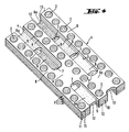
- vier Karten gestapelt in isometrischer Darstellung.
- Die Karte, 1, z.B. aus grünem keramischem Material weist (2N-1) mit N = 2, 3, 4, 5 parallel zueinander verlaufende und symmetrieachsensymmetrisch angeordnete Lochreihen auf. Die Löcher 2 einer Lochreihe haben einen Abstand von 1 bis 10 mm untereinander, d.h. die zwischen ihnen verbleibenden Stege 8 sind 1 bis 10 mm breit. Zwischen den Lochreihen sind Ausnehmungen 3, 4, 5 unterschiedlicher Länge angeordnet.
- Die Ausnehmungen sind 1 bis 50 mm breit und haben einen Abstand (Steg 9) von 1 bis 10 mm zu den Lochreihen. Alle Ausnehmungen beginnen am Rand der Karte, d.h. sie schneiden ihn. Dabei schneidet die längste Ausnehmung 3 und die zweitlängste Ausnehmung 4 den gleichen Kartenrand 10. Die kürzeste Ausnehmung 5 ist der zweitlängsten gegenüber angeordnet und schneidet den Kartenrand 11. Die Länge der zwischen den Ausnehmungen 4 und 5 sowie zwischen der Ausnehmung 3 und dem Kartenrand verbleibenden Stege 6,6a beträgt 25 % ± 0 bis ± 6 % der Kartenlänge in Richtung der Lochreihen. Gemäß Figur 1 beträgt die Länge der Stege 6,6a 25 %, gemäß Figur 2 ca. 20 % der Kartenlänge. Bei verkürzten Stegen 6,6a überlappen sich die Ausnehmungen benachbarter Karten, so daß senkrecht zu den flachen Kanälen durchgehende Kanäle entstehen, über die die einzelnen flachen Kanäle untereinander verbunden sind. Dadurch wird eine bessere Verwirbelung und Vermischung des jeweiligen Stoffstromes bewirkt. Sollen größere Einheiten aus den Strukturen zusammengebaut werden, kann es von Vorteil sein, den Kartenrand im Bereich des Steges 6a mit einer Ausnehmung 12 zu versehen, deren Länge bis zu 3 % der Kartenlänge betragen kann. Sind die Stege 6,6a länger als 25 % der Kartenlänge, erhalten sie die Funktion von Leitflächen bzw. Kühlrippen.
- Grüne Karten aus keramischem Material lassen sich nicht in beliebiger Dicke herstellen. Durch Aufeinanderlaminieren einzelner Karten können Platten und Blöcke hergestellt werden, die dann jeweils ein vielfaches der Kartendicke aufweisen. Durch anschließendes Brennen wird der laminierte Block zu einem homogenen keramischen Bauteil. Neben keramischem Material können auch metallische Bleche oder Kunststoffolien für die gestanzten Karten in Betracht kommen.
- Durch diese Aufbauvarianten kann das Flächenverhältnis von Lochkanälen zu flachen Kanälen beeinflußt werden. Fläche und Kanalquerschnitt auf der Lochseite bleiben dabei immer konstant. Fläche und Kanalquerschnitt der flachen Kanäle können jedoch durch die Anordnung von mehreren Karten in gleicher Lage variiert werden. Der durchströmte Gesamtquerschnitt bleibt auch auf der Seite der flachen Kanäle immer gleich. Die Stapelung von Einzelkarten ergibt das größte Flächenverhältnis. Eine Stapelung von beispielsweise jeweils fünf Karten 1 in gleicher Lage reduziert die Fläche der verbindungsstege 6, 6a auf 1/5 und vergrößert die einzelnen Kanalquerschnitte auf das fünffache bei gleichbleibendem durchströmten Gesamtquerschnitt und gleichbleibenden Verhältnissen auf der Lochseite. Das heißt, bei Wärmetauschern mit gleichen Außenabmessungen kann das Flächenverhältnis auf einfache Weise variiert und somit den Erfordernissen angepaßt werden. Die Locher 2, in beliebiger Form und Anzahl sind derart auf der Karte angeordnet, daß sie bei gewendeter Karte 1 immer mit den Löchern 2 der darüber bzw. darunter liegenden Karte deckungsgleich übereinstimmen (Figur 4). Die Stapelfolge (Figur 3), durch die eine Durchlässigkeit der Struktur für das zweite Medium erreicht wird, hat einen Viererrhythmus. Jeweils eine oder mehrere gleichliegende Karten 1 werden durch wenden in die Lagen A, B, C und D gebracht und in dieser Lage und Reihenfolge aufeinander laminiert. Das heißt, eine bestimmte Kartenecke - durch Pluszeichen angedeutet - kommt nacheinander an alle vier Stapelecken zu liegen. So entsteht Karte B durch wenden von Karte A um die Symmetrieachse, Karte C durch Wenden von Karte B um die Senkrechte zur Symmetrieachse und Karte D durch Wenden von Karte C um die Symmetrieachse (Figur 3). Die Stapel aus vier Karten werden solange wiederholt, bis die gewünschte Blockhöhe erreicht ist. Der Block kann durch jeweils eine Deckkarte abgeschlossen werden, die lediglich die Lochreihen enthält.
- Die beschriebene Karte 1 kann sowohl in Längs- als auch in Querrichtung zu größeren Einheiten zusammengefaßt werden.
- In Längsrichtung geschieht dies einfach durch aneinanderreihen, in Querrichtung entfällt jeweils eine Lochreihe, denn die Anzahl der Lochreihen muß immer ungerade sein.
Claims (3)
- Karte zum Aufbau von durchlässigen Strukturen, dadurch gekennzeichnet, daß die Karte (1) 2N-1, mit N = 2, 3, 4 oder 5 parallel zueinander verlaufende und symmetrieachsensymmetrisch angeordnete Lochreihen aufweist, zwischen den Lochreihen drei Ausnehmungen (3, 4, 5) unterschiedlicher Länge angeordnet sind, die den Kartenrand (10, 11) schneiden, wobei die längste (3) und eine der beiden kürzeren (4, 5) in den gleichen Kartenrand (10) münden und die kürzeste (5) der zweitlängsten (4) gegenübersteht und die zwischen den Ausnehmungen (4, 5) bzw. der Ausnehmung (3) und dem Kartenrand (11) verbleibenden Stege (6, 6a) eine Länge von 25 % ± 0 bis 6 % bezogen auf die durch die Lochreihenrichtung festgelegte Länge der Karte (1) aufweisen.
- Karte nach Anspruch 1, dadurch gekennzeichnet, daß die zwischen den Löchern (2) einer Lochreihe und den Lochreihen und den Ausnehmungen (3, 4, 5) verbleibenden Stege (8, 9) 1 bis 10 mm breit sind und die Breite der Ausnehmungen (3, 4, 5) 1 bis 50mm beträgt.
- Durchlässige Struktur, hergestellt aus Karten gemäß Anspruch 1, dadurch gekennzeichnet, daß die Karten (1) abwechselnd durch Wenden um die durch die mittlere Lochreihe definierte Symmetrieachse und um die Senkrechte dazu übereinander gestapelt sind, wobei die Löcher (2) bei gestapelten Karten durchgehende Kanäle bilden und die Ausnehmungen (3, 4, 5) flache Kanäle ausbilden, die sich im wesentliche quer zu den durchgehenden Kanälen erstrecken.
Applications Claiming Priority (2)
| Application Number | Priority Date | Filing Date | Title |
|---|---|---|---|
| DE4022654 | 1990-07-17 | ||
| DE4022654A DE4022654A1 (de) | 1990-07-17 | 1990-07-17 | Karte aus keramischem material zum aufbau von durchlaessigen strukturen |
Publications (2)
| Publication Number | Publication Date |
|---|---|
| EP0467217A1 EP0467217A1 (de) | 1992-01-22 |
| EP0467217B1 true EP0467217B1 (de) | 1994-03-09 |
Family
ID=6410416
Family Applications (1)
| Application Number | Title | Priority Date | Filing Date |
|---|---|---|---|
| EP91111529A Expired - Lifetime EP0467217B1 (de) | 1990-07-17 | 1991-07-11 | Karte zum Aufbau von durchlässigen Strukturen |
Country Status (12)
| Country | Link |
|---|---|
| US (1) | US5212004A (de) |
| EP (1) | EP0467217B1 (de) |
| JP (1) | JPH04227482A (de) |
| AT (1) | ATE102702T1 (de) |
| CA (1) | CA2047118A1 (de) |
| DE (2) | DE4022654A1 (de) |
| DK (1) | DK0467217T3 (de) |
| ES (1) | ES2051056T3 (de) |
| FI (1) | FI913412A7 (de) |
| IE (1) | IE912479A1 (de) |
| NO (1) | NO174072C (de) |
| PT (1) | PT98338A (de) |
Families Citing this family (18)
| Publication number | Priority date | Publication date | Assignee | Title |
|---|---|---|---|---|
| DE4238192C2 (de) * | 1992-11-12 | 1994-09-29 | Hoechst Ceram Tec Ag | Durchlässige Struktur |
| DE4238191C2 (de) * | 1992-11-12 | 1994-09-08 | Hoechst Ceram Tec Ag | Durchlässige Strukturen |
| DE4238190C2 (de) * | 1992-11-12 | 1994-09-08 | Hoechst Ceram Tec Ag | Keramikmodul |
| EP0651222A3 (de) * | 1993-11-03 | 1995-10-25 | Hoechst Ceram Tec Ag | Verfahren zum Betreiben von Wärmetauschern. |
| US5911273A (en) * | 1995-08-01 | 1999-06-15 | Behr Gmbh & Co. | Heat transfer device of a stacked plate construction |
| DE19528116B4 (de) * | 1995-08-01 | 2007-02-15 | Behr Gmbh & Co. Kg | Wärmeübertrager mit Platten-Sandwichstruktur |
| EP0866940B1 (de) * | 1995-12-01 | 2002-02-13 | Chart Heat Exchangers Limited | Wärmetauscher |
| ATE292779T1 (de) | 1997-06-03 | 2005-04-15 | Chart Heat Exchangers Ltd Part | Wärmetauscher und/oder vorrichtung zur mischung von fluiden |
| US6167952B1 (en) | 1998-03-03 | 2001-01-02 | Hamilton Sundstrand Corporation | Cooling apparatus and method of assembling same |
| US6386278B1 (en) * | 1998-08-04 | 2002-05-14 | Jurgen Schulz-Harder | Cooler |
| EP1166026B1 (de) | 1999-03-27 | 2006-12-20 | CHART HEAT EXCHANGERS Limited Partnership | Wärmetauscher |
| AU2001245588A1 (en) * | 2000-03-10 | 2001-09-24 | Satcon Technology Corporation | High performance cold plate for electronic cooling |
| EP1397633A2 (de) * | 2001-06-06 | 2004-03-17 | Battelle Memorial Institute | Mikro-kanälen wärmeübertrager |
| US7883670B2 (en) * | 2002-02-14 | 2011-02-08 | Battelle Memorial Institute | Methods of making devices by stacking sheets and processes of conducting unit operations using such devices |
| US7862633B2 (en) * | 2007-04-13 | 2011-01-04 | Battelle Memorial Institute | Method and system for introducing fuel oil into a steam reformer with reduced carbon deposition |
| US20130056186A1 (en) * | 2011-09-06 | 2013-03-07 | Carl Schalansky | Heat exchanger produced from laminar elements |
| TWM469450U (zh) * | 2013-01-21 | 2014-01-01 | Huang-Han Chen | 冷凝排 |
| TWI835709B (zh) * | 2016-04-18 | 2024-03-21 | 俄勒岡州大學 | 層壓的微通道熱交換器 |
Family Cites Families (9)
| Publication number | Priority date | Publication date | Assignee | Title |
|---|---|---|---|---|
| DE843094C (de) * | 1942-02-10 | 1952-07-03 | Separator Ab | Abstuetzvorrichtung fuer die Platten von Waermeaustauschern |
| NL80122C (de) * | 1948-07-24 | |||
| DE3136253A1 (de) * | 1981-09-12 | 1983-03-31 | Rosenthal Technik Ag, 8672 Selb | Verfahren und vorrichtung zum herstellen von waermetauschern aus keramischen folien |
| DE3643749A1 (de) * | 1986-12-20 | 1988-06-30 | Hoechst Ag | Waermetauschermodul aus gebranntem keramischen material |
| DE3643750A1 (de) * | 1986-12-20 | 1988-06-30 | Hoechst Ag | Waermetauschermodul aus gebranntem keramischen material |
| US4880055A (en) * | 1988-12-07 | 1989-11-14 | Sundstrand Corporation | Impingement plate type heat exchanger |
| US4936380A (en) * | 1989-01-03 | 1990-06-26 | Sundstrand Corporation | Impingement plate type heat exchanger |
| US5016707A (en) * | 1989-12-28 | 1991-05-21 | Sundstrand Corporation | Multi-pass crossflow jet impingement heat exchanger |
| US5099915A (en) * | 1990-04-17 | 1992-03-31 | Sundstrand Corporation | Helical jet impingement evaporator |
-
1990
- 1990-07-17 DE DE4022654A patent/DE4022654A1/de not_active Withdrawn
-
1991
- 1991-07-11 AT AT91111529T patent/ATE102702T1/de not_active IP Right Cessation
- 1991-07-11 DE DE91111529T patent/DE59101143D1/de not_active Expired - Fee Related
- 1991-07-11 DK DK91111529.3T patent/DK0467217T3/da active
- 1991-07-11 EP EP91111529A patent/EP0467217B1/de not_active Expired - Lifetime
- 1991-07-11 ES ES91111529T patent/ES2051056T3/es not_active Expired - Lifetime
- 1991-07-15 FI FI913412A patent/FI913412A7/fi not_active Application Discontinuation
- 1991-07-16 PT PT98338A patent/PT98338A/pt not_active Application Discontinuation
- 1991-07-16 NO NO912790A patent/NO174072C/no unknown
- 1991-07-16 IE IE247991A patent/IE912479A1/en unknown
- 1991-07-16 CA CA002047118A patent/CA2047118A1/en not_active Abandoned
- 1991-07-16 US US07/730,692 patent/US5212004A/en not_active Expired - Fee Related
- 1991-07-17 JP JP3176535A patent/JPH04227482A/ja active Pending
Also Published As
| Publication number | Publication date |
|---|---|
| CA2047118A1 (en) | 1992-01-18 |
| ES2051056T3 (es) | 1994-06-01 |
| ATE102702T1 (de) | 1994-03-15 |
| FI913412L (fi) | 1992-01-18 |
| DE59101143D1 (de) | 1994-04-14 |
| JPH04227482A (ja) | 1992-08-17 |
| EP0467217A1 (de) | 1992-01-22 |
| DE4022654A1 (de) | 1992-01-23 |
| NO912790D0 (no) | 1991-07-16 |
| FI913412A0 (fi) | 1991-07-15 |
| DK0467217T3 (da) | 1994-06-27 |
| NO174072C (no) | 1994-03-09 |
| NO174072B (no) | 1993-11-29 |
| FI913412A7 (fi) | 1992-01-18 |
| IE912479A1 (en) | 1992-01-29 |
| PT98338A (pt) | 1993-09-30 |
| NO912790L (no) | 1992-01-20 |
| US5212004A (en) | 1993-05-18 |
Similar Documents
| Publication | Publication Date | Title |
|---|---|---|
| DE19528117B4 (de) | Wärmeübertrager mit Plattenstapelaufbau | |
| EP0467217A1 (de) | Karte zum Aufbau von durchlässigen Strukturen | |
| EP0866500B1 (de) | Kühler bzw. Wärmesenke für elektrische Bauelemente oder Schaltkreise sowie elektrischer Schaltkreis mit einer solchen Wärmesenke | |
| DE19528116B4 (de) | Wärmeübertrager mit Platten-Sandwichstruktur | |
| EP0545956B1 (de) | Taschenfederkern | |
| DE10118625B4 (de) | Wellenförmige Lamelle mit Versatz für Plattenwärmetauscher | |
| DE69616959T2 (de) | Wärmeaustauschelement | |
| DE69023530T2 (de) | Einheitlich gewebte Mehrschichtverbundgewebe mit Mehrfachöffnungen. | |
| DE69803373T2 (de) | Verdrahtung von Zellen in logischen Feldern | |
| DE69121862T2 (de) | Bauelement für einen wabenförmigen Kern und eine Plattenstruktur mit diesem Wabenkern | |
| EP2045556B1 (de) | Plattenwärmetauscher | |
| DE3943179A1 (de) | Kaltchassis fuer eine elektronische leiterplatte in einem elektronischen bausteinsystem | |
| EP0978874A2 (de) | Kühler | |
| EP0321480B1 (de) | Plattenwärmeaustauscher | |
| DE202022101528U1 (de) | Einsetzteil für einen Strahlregler | |
| DE4238190C2 (de) | Keramikmodul | |
| AT393162B (de) | Plattenwaermeaustauscher mit besonderem profil der waermeaustauschzone | |
| EP0622493A2 (de) | Bausatz aus Betonplatten | |
| EP0159685B1 (de) | Verfahren zur Herstellung der Platten eines Plattenwärmetauschers und aus den Platten hergestellter Wärmetauscher | |
| DE19853750A1 (de) | Kühler zur Verwendung als Wärmesenke für elektrische oder elektronische Komponenten | |
| DE20209511U1 (de) | Wickelmodul zur Crossflow-Filtration | |
| DE102023121426A1 (de) | Vorrichtung zur Führung von wenigstens zwei Fluidströmen, elektrochemisches System und Verfahren zum Herstellen einer Vorrichtung mit einem Wärmeübertragerkörper | |
| AT412817B (de) | Keramischer wabenkörper zur verwendung in einer thermischen abgasbehandlungsvorrichtung | |
| DE3424159C2 (de) | ||
| DE4238192A1 (de) | Durchlässige Strukturen |
Legal Events
| Date | Code | Title | Description |
|---|---|---|---|
| PUAI | Public reference made under article 153(3) epc to a published international application that has entered the european phase |
Free format text: ORIGINAL CODE: 0009012 |
|
| AK | Designated contracting states |
Kind code of ref document: A1 Designated state(s): AT BE CH DE DK ES FR GB GR IT LI LU NL SE |
|
| 17P | Request for examination filed |
Effective date: 19920506 |
|
| 17Q | First examination report despatched |
Effective date: 19930120 |
|
| GRAA | (expected) grant |
Free format text: ORIGINAL CODE: 0009210 |
|
| AK | Designated contracting states |
Kind code of ref document: B1 Designated state(s): AT BE CH DE DK ES FR GB GR IT LI LU NL SE |
|
| REF | Corresponds to: |
Ref document number: 102702 Country of ref document: AT Date of ref document: 19940315 Kind code of ref document: T |
|
| REF | Corresponds to: |
Ref document number: 59101143 Country of ref document: DE Date of ref document: 19940414 |
|
| ITF | It: translation for a ep patent filed | ||
| REG | Reference to a national code |
Ref country code: ES Ref legal event code: FG2A Ref document number: 2051056 Country of ref document: ES Kind code of ref document: T3 |
|
| GBT | Gb: translation of ep patent filed (gb section 77(6)(a)/1977) |
Effective date: 19940518 |
|
| REG | Reference to a national code |
Ref country code: DK Ref legal event code: T3 |
|
| PGFP | Annual fee paid to national office [announced via postgrant information from national office to epo] |
Ref country code: ES Payment date: 19940707 Year of fee payment: 4 |
|
| ET | Fr: translation filed | ||
| PGFP | Annual fee paid to national office [announced via postgrant information from national office to epo] |
Ref country code: GR Payment date: 19940722 Year of fee payment: 4 |
|
| REG | Reference to a national code |
Ref country code: GR Ref legal event code: FG4A Free format text: 3011832 |
|
| EPTA | Lu: last paid annual fee | ||
| PLBE | No opposition filed within time limit |
Free format text: ORIGINAL CODE: 0009261 |
|
| STAA | Information on the status of an ep patent application or granted ep patent |
Free format text: STATUS: NO OPPOSITION FILED WITHIN TIME LIMIT |
|
| EAL | Se: european patent in force in sweden |
Ref document number: 91111529.3 |
|
| 26N | No opposition filed | ||
| PG25 | Lapsed in a contracting state [announced via postgrant information from national office to epo] |
Ref country code: ES Free format text: LAPSE BECAUSE OF THE APPLICANT RENOUNCES Effective date: 19950712 |
|
| PG25 | Lapsed in a contracting state [announced via postgrant information from national office to epo] |
Ref country code: GR Free format text: THE PATENT HAS BEEN ANNULLED BY A DECISION OF A NATIONAL AUTHORITY Effective date: 19960131 |
|
| REG | Reference to a national code |
Ref country code: GR Ref legal event code: MM2A Free format text: 3011832 |
|
| PGFP | Annual fee paid to national office [announced via postgrant information from national office to epo] |
Ref country code: FR Payment date: 19970619 Year of fee payment: 7 |
|
| PGFP | Annual fee paid to national office [announced via postgrant information from national office to epo] |
Ref country code: CH Payment date: 19970620 Year of fee payment: 7 |
|
| PGFP | Annual fee paid to national office [announced via postgrant information from national office to epo] |
Ref country code: DE Payment date: 19970922 Year of fee payment: 7 |
|
| PGFP | Annual fee paid to national office [announced via postgrant information from national office to epo] |
Ref country code: SE Payment date: 19980701 Year of fee payment: 8 |
|
| PGFP | Annual fee paid to national office [announced via postgrant information from national office to epo] |
Ref country code: GB Payment date: 19980702 Year of fee payment: 8 |
|
| PGFP | Annual fee paid to national office [announced via postgrant information from national office to epo] |
Ref country code: BE Payment date: 19980722 Year of fee payment: 8 |
|
| PGFP | Annual fee paid to national office [announced via postgrant information from national office to epo] |
Ref country code: DK Payment date: 19980727 Year of fee payment: 8 |
|
| PG25 | Lapsed in a contracting state [announced via postgrant information from national office to epo] |
Ref country code: LI Free format text: LAPSE BECAUSE OF NON-PAYMENT OF DUE FEES Effective date: 19980731 Ref country code: CH Free format text: LAPSE BECAUSE OF NON-PAYMENT OF DUE FEES Effective date: 19980731 |
|
| PGFP | Annual fee paid to national office [announced via postgrant information from national office to epo] |
Ref country code: NL Payment date: 19980731 Year of fee payment: 8 Ref country code: AT Payment date: 19980731 Year of fee payment: 8 |
|
| PGFP | Annual fee paid to national office [announced via postgrant information from national office to epo] |
Ref country code: LU Payment date: 19980826 Year of fee payment: 8 |
|
| REG | Reference to a national code |
Ref country code: CH Ref legal event code: PL |
|
| PG25 | Lapsed in a contracting state [announced via postgrant information from national office to epo] |
Ref country code: FR Free format text: LAPSE BECAUSE OF NON-PAYMENT OF DUE FEES Effective date: 19990331 |
|
| PG25 | Lapsed in a contracting state [announced via postgrant information from national office to epo] |
Ref country code: DE Free format text: LAPSE BECAUSE OF NON-PAYMENT OF DUE FEES Effective date: 19990501 |
|
| REG | Reference to a national code |
Ref country code: FR Ref legal event code: ST |
|
| PG25 | Lapsed in a contracting state [announced via postgrant information from national office to epo] |
Ref country code: LU Free format text: LAPSE BECAUSE OF NON-PAYMENT OF DUE FEES Effective date: 19990711 Ref country code: GB Free format text: LAPSE BECAUSE OF NON-PAYMENT OF DUE FEES Effective date: 19990711 Ref country code: AT Free format text: LAPSE BECAUSE OF NON-PAYMENT OF DUE FEES Effective date: 19990711 |
|
| PG25 | Lapsed in a contracting state [announced via postgrant information from national office to epo] |
Ref country code: SE Free format text: THE PATENT HAS BEEN ANNULLED BY A DECISION OF A NATIONAL AUTHORITY Effective date: 19990730 |
|
| PG25 | Lapsed in a contracting state [announced via postgrant information from national office to epo] |
Ref country code: BE Free format text: LAPSE BECAUSE OF NON-PAYMENT OF DUE FEES Effective date: 19990731 |
|
| PG25 | Lapsed in a contracting state [announced via postgrant information from national office to epo] |
Ref country code: DK Free format text: LAPSE BECAUSE OF NON-PAYMENT OF DUE FEES Effective date: 19990802 |
|
| REG | Reference to a national code |
Ref country code: ES Ref legal event code: FD2A Effective date: 19991007 |
|
| BERE | Be: lapsed |
Owner name: HOECHST A.G. Effective date: 19990731 |
|
| PG25 | Lapsed in a contracting state [announced via postgrant information from national office to epo] |
Ref country code: NL Free format text: LAPSE BECAUSE OF NON-PAYMENT OF DUE FEES Effective date: 20000201 |
|
| GBPC | Gb: european patent ceased through non-payment of renewal fee |
Effective date: 19990711 |
|
| REG | Reference to a national code |
Ref country code: DK Ref legal event code: EBP |
|
| EUG | Se: european patent has lapsed |
Ref document number: 91111529.3 |
|
| NLV4 | Nl: lapsed or anulled due to non-payment of the annual fee |
Effective date: 20000201 |
|
| PG25 | Lapsed in a contracting state [announced via postgrant information from national office to epo] |
Ref country code: IT Free format text: LAPSE BECAUSE OF NON-PAYMENT OF DUE FEES Effective date: 20050711 |