EP0466366A1 - Kodiergerät für ein Videosignal - Google Patents
Kodiergerät für ein Videosignal Download PDFInfo
- Publication number
- EP0466366A1 EP0466366A1 EP19910305828 EP91305828A EP0466366A1 EP 0466366 A1 EP0466366 A1 EP 0466366A1 EP 19910305828 EP19910305828 EP 19910305828 EP 91305828 A EP91305828 A EP 91305828A EP 0466366 A1 EP0466366 A1 EP 0466366A1
- Authority
- EP
- European Patent Office
- Prior art keywords
- step width
- quantizing step
- prediction
- circuit
- quantizing
- Prior art date
- Legal status (The legal status is an assumption and is not a legal conclusion. Google has not performed a legal analysis and makes no representation as to the accuracy of the status listed.)
- Granted
Links
Images
Classifications
-
- H—ELECTRICITY
- H04—ELECTRIC COMMUNICATION TECHNIQUE
- H04N—PICTORIAL COMMUNICATION, e.g. TELEVISION
- H04N19/00—Methods or arrangements for coding, decoding, compressing or decompressing digital video signals
- H04N19/10—Methods or arrangements for coding, decoding, compressing or decompressing digital video signals using adaptive coding
- H04N19/134—Methods or arrangements for coding, decoding, compressing or decompressing digital video signals using adaptive coding characterised by the element, parameter or criterion affecting or controlling the adaptive coding
- H04N19/136—Incoming video signal characteristics or properties
- H04N19/14—Coding unit complexity, e.g. amount of activity or edge presence estimation
-
- H—ELECTRICITY
- H04—ELECTRIC COMMUNICATION TECHNIQUE
- H04N—PICTORIAL COMMUNICATION, e.g. TELEVISION
- H04N19/00—Methods or arrangements for coding, decoding, compressing or decompressing digital video signals
- H04N19/10—Methods or arrangements for coding, decoding, compressing or decompressing digital video signals using adaptive coding
- H04N19/102—Methods or arrangements for coding, decoding, compressing or decompressing digital video signals using adaptive coding characterised by the element, parameter or selection affected or controlled by the adaptive coding
- H04N19/124—Quantisation
- H04N19/126—Details of normalisation or weighting functions, e.g. normalisation matrices or variable uniform quantisers
-
- H—ELECTRICITY
- H04—ELECTRIC COMMUNICATION TECHNIQUE
- H04N—PICTORIAL COMMUNICATION, e.g. TELEVISION
- H04N19/00—Methods or arrangements for coding, decoding, compressing or decompressing digital video signals
- H04N19/10—Methods or arrangements for coding, decoding, compressing or decompressing digital video signals using adaptive coding
- H04N19/169—Methods or arrangements for coding, decoding, compressing or decompressing digital video signals using adaptive coding characterised by the coding unit, i.e. the structural portion or semantic portion of the video signal being the object or the subject of the adaptive coding
- H04N19/17—Methods or arrangements for coding, decoding, compressing or decompressing digital video signals using adaptive coding characterised by the coding unit, i.e. the structural portion or semantic portion of the video signal being the object or the subject of the adaptive coding the unit being an image region, e.g. an object
- H04N19/176—Methods or arrangements for coding, decoding, compressing or decompressing digital video signals using adaptive coding characterised by the coding unit, i.e. the structural portion or semantic portion of the video signal being the object or the subject of the adaptive coding the unit being an image region, e.g. an object the region being a block, e.g. a macroblock
-
- H—ELECTRICITY
- H04—ELECTRIC COMMUNICATION TECHNIQUE
- H04N—PICTORIAL COMMUNICATION, e.g. TELEVISION
- H04N19/00—Methods or arrangements for coding, decoding, compressing or decompressing digital video signals
- H04N19/60—Methods or arrangements for coding, decoding, compressing or decompressing digital video signals using transform coding
- H04N19/61—Methods or arrangements for coding, decoding, compressing or decompressing digital video signals using transform coding in combination with predictive coding
-
- H—ELECTRICITY
- H04—ELECTRIC COMMUNICATION TECHNIQUE
- H04N—PICTORIAL COMMUNICATION, e.g. TELEVISION
- H04N19/00—Methods or arrangements for coding, decoding, compressing or decompressing digital video signals
- H04N19/10—Methods or arrangements for coding, decoding, compressing or decompressing digital video signals using adaptive coding
- H04N19/134—Methods or arrangements for coding, decoding, compressing or decompressing digital video signals using adaptive coding characterised by the element, parameter or criterion affecting or controlling the adaptive coding
- H04N19/146—Data rate or code amount at the encoder output
- H04N19/152—Data rate or code amount at the encoder output by measuring the fullness of the transmission buffer
Definitions
- the present invention relates to a high-efficient coding apparatus for a video signal which is used for a TV phone, a video conference, observation, and the like.
- a conventional high-efficient coding apparatus serves to compute a prediction error by using the prediction having both of the motion compensated inter frame prediction and the intra frame prediction mingled therein, either one of the motion compensated inter frame prediction and the intra frame prediction, or selectively using both of those two predictions, orthogonally translate the prediction error at each block (for example, 8 x 8) composed of a set of pixels, and code the resulting coefficients. Then, the description will be directed to how the conventional high-efficient coding apparatus is used for transmission.
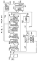
- Fig. 1 shows the conventional high-efficient coding apparatus.
- 302 denotes an analog-to-digital converter (referred to as an A/D converter) which is connected to a subtracter 304 through a line 301 and a motion vector detecting circuit 324 through a line 303.
- the subtracter 304 is connected to a prediction circuit 322 through a line 325 and to an orthogonal transform circuit 306 through a line 305.
- the orthogonal transform circuit 306 is connected to a coefficient quantizing circuit 308 through a line 307.
- the coefficient quantizing circuit 308 is connected to a quantized coefficients coding circuit 310 through a line 309 and a quantizing step width control circuit 330 through a line 331.
- the quantized coefficients coding circuit 310 is connected to a quantized coefficients decoding circuit 312 and a line coding circuit 326 through a line 311.
- the quantized coefficients coding circuit 312 is connected to a coefficients dequantizing circuit 314 through a line 313.
- the coefficients dequantizing circuit 314 is connected to an orthogonal inverse transform circuit 316 through a line 315 and to a quantizing step width control circuit 330 through a line 331.
- the orthogonal transform circuit 316 is connected to an adder 318 through a line 317.
- the adder 318 is connected to a prediction circuit 322 through a line 325 and to a frame memory 320 through a line 319.
- the frame memory 320 is connected to the prediction circuit 322 and the motion vector detecting circuit 324 through a line 321.
- the motion vector detecting circuit 324 is connected to the prediction circuit 322 and the transmission coding circuit 326 through a line 323.
- the transmission coding circuit 326 is connected to a transmission buffer 328 through a line 327.
- the transmission buffer 328 is connected to the quantizing step width control circuit 330 through a line 329 and to the outside line through a line 332.
- the quantizing step width control circuit 330 is connected to the coefficient quantizing circuit 308, the coefficients dequantizing circuit 314, and the transmission coding circuit 326 through a line 331.
- an analog video signal is inputted to the A/D converter 302 through the line 301.
- the A/D converter 302 serves to convert the analog video signal into a digital video signal and send the digital video signal to the subtracter 304 and the motion vector detecting circuit 324 through the line 303.
- the motion vector detecting circuit 324 serves to detect a motion vector at each block composed of a set of pixels by using the inputted digital video signal and a reproduced pixel value of a frame given before being read from the frame memory 320.
- the detected motion vector is sent to the prediction circuit 322 and the transmission coding circuit 326 through the line 323.
- the prediction circuit 322 serves to use a prediction having the motion compensated inter frame prediction and the intra frame prediction mingled therein, either one of the motion compensated inter frame prediction and the intra frame prediction, or to selectively use both of the predictions for performing the prediction based on the motion vector, the current frame read from the frame memory 320, and (or) the reproduced pixel values of the previous frame.
- the computed predicted value is inputted to the subtracter 304 and the adder 318 through the line 325.
- the subtracter 304 serves to compute the prediction error based on the inputted digital video signal.
- the prediction error is sent to the orthogonal transform circuit 306 which serves to orthogonally transform the prediction error at each block composed of a set of pixels.
- the orthogonal transform circuit 306 sends out the orthogonally transformed coefficients to the coefficient quantizing circuit 308.
- the coefficient quantizing circuit 308 serves to quantize the orthogonally transformed coefficients.
- the quantizing step width used for quantization is defined in the quantizing step width control circuit 330.
- the quantizing step width control circuit 330 serves to control the quantizing step width according to the residual information in the transmission buffer 328, that is, control the quantizing step to be longer for suppressing the amount of the information to be generated if the transmission buffer 328 stores a large amount of the residual information and to be smaller for transmitting more fine image if the transmission buffer 328 stores a smaller amount of the residual information.
- the quantizing step width is inputted to the transmission coding circuit 326 through the line 331.
- the transmission coding circuit 326 serves to code the quantizing step and send the result to a decoder.
- the coefficient quantized in the coefficient quantizing circuit 308 is sent to the quantized coefficients coding circuit 310 in which the quantized coefficients are coded.
- the coded coefficients are inputted to the transmission coding circuit 326 through the line 311 and to the quantized coefficients decoding circuit 312 in which the code coefficients are locally decoded.
- the resulting signal is sent to the coefficient dequantizing circuit 314 in which the signal is dequantized.
- the same width of the dequantizing step as the step width used in the coefficient quantizing circuit 308 is inputted from the quantizing step width control circuit 330 to the coefficient dequantizing circuit 314 through the line 331. Then, the dequantized coefficient is sent to the orthogonal inverse transform circuit 316 in which the dequantized coefficient is inversely transformed for reproducing a prediction error. The predicted value is added to the reproduced prediction error in the adder 318 for the purpose of reproducing the pixel values. The reproduced pixel values are written in the frame memory 320.
- the information about the motion vector, the information about the orthogonal transform coefficient, and the quantizing step width are inputted to the transmission coding circuit in which these pieces of information are coded for allowing them to be sent on the outer line. Then, the coded signals are inputted to the transmission buffer 328 in which these signals are smoothed in light of speed and then the smoothed signals are sent to the outer line through the line 322.
- the high-efficient coding apparatus for video signal is capable of transmitting a moving image with little degradation of image quality according to a constant rate (for example, 64 kb/s, 384 kb/s) or according to a variable rate by controlling the quantizing step width depending on the amount of residual information stored in the transmission buffer 328.
- a constant rate for example, 64 kb/s, 384 kb/s
- a variable rate by controlling the quantizing step width depending on the amount of residual information stored in the transmission buffer 328.
- the foregoing conventional high-efficient coding apparatus for video signal is, however, arranged to define a quantizing step width depending on the amount of residual information stored in the transmission buffer 328. That is, the high-efficient coding apparatus serves to control the quantizing step width not depending on the quality of an inputted moving image but the amount of residual information.
- the conventional coding apparatus is, thus, uncapable of controlling a quantizing step width based on an inputted image so that a background of an inputted image can be finely quantized or the moving part of an inputted image can be finely quantized.
- the present invention is designed to solve the foregoing problems. It is an object of the present invention to provide an excellent high-efficient coding apparatus for video signal which is capable of controlling a quantizing step width finely according to the quality of the inputted image.
- the present invention provides a high-efficient coding apparatus for video signal which provides a circuit for defining an upper limit value and a lower limit value of a quantizing step width using a prediction error for a pixel or an average value of two or more prediction errors for the purpose of finely controlling the quantizing step width depending on the quality of an inputted image.
- the present invention can produce the following effects in light of the foregoing arrangement.
- the quality of the inputted image is reflected on a prediction error of a pixel or an average value of prediction errors of two or more pixels.
- the area with a small prediction error indicates a background area.
- the prediction error becomes larger, the area to be indicated is changed as the background area where an object has just moved, the area having no edge in the moving area, and the area having an edge in the moving area in sequence.
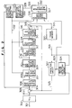
- Fig. 2 shows arrangement of an embodiment of the present invention. Some of the components shown in Fig. 2 have the same arrangement and operation as those shown in Fig. 1, which are indicated by the same numbers as those shown in Fig. 1. The following description will be directed to the arrangement and the operation of the different components shown in Fig. 2 from the components shown in Fig. 1. According to this embodiment, the present invention is applied to the transmission. However, the invention may apply to various kinds of applications which employ a compression function of image information.
- 101 denotes a quantizing step width restricting circuit which is connected to a subtracter 304 through a line 305, a coefficient quantizing circuit 308 through a line 102, and a coefficient reverse quantizing circuit 314 and a line coding circuit 326 through a line 103.
- the quantizing step width restricting circuit 101 serves to define an upper limit value of the quantizing step width output from the quantizing step width control circuit 330 through the line 103.
- the upper limit value is defined depending on a prediction error inputted from the substrater 304 to the quantizing step width restricting circuit through the line 305. Concretely, the upper limit value is defined depending on an average value of prediction errors at each block (8 x 8 pixels, for example) or at each set of blocks. The orthogonal transform is carried out on each block. In this case, the following relation is roughly established between the average value of the prediction errors and each part of the screen.
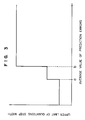
- Fig. 3 shows how the upper limit value of the quantizing step width is set in this case.
- a and b have to be defined according to each way of use and object.
- the upper limit value of the quantizing step width is defined depending on the average value of prediction errors at each block or each set of blocks.
- the present embodiment provides an effect that the quantizing step width can be finely controlled depending on the quality of the inputted image for the purpose of improving an image quality of a specified portion of the inputted image, for example.
- the upper limit value of the quantizing step value is defined merely by using the average value of the prediction errors. It is, however, possible to use another parameter (for example, a quantizing step width inputted from the quantizing step width control circuit 330 through the line 103 shown in Fig. 2) for more finely specify each part of the image.
- the present embodiment has merely described how to set the upper limit value of the quantizing step width. However, it is also possible to set a lower limit value of the quantizing step width for an insignificant part of the image.
Landscapes
- Engineering & Computer Science (AREA)
- Multimedia (AREA)
- Signal Processing (AREA)
- Compression Or Coding Systems Of Tv Signals (AREA)
- Color Television Systems (AREA)
Applications Claiming Priority (2)
| Application Number | Priority Date | Filing Date | Title |
|---|---|---|---|
| JP180827/90 | 1990-07-09 | ||
| JP18082790A JP2892783B2 (ja) | 1990-07-09 | 1990-07-09 | 動画像信号の符号化装置 |
Publications (2)
| Publication Number | Publication Date |
|---|---|
| EP0466366A1 true EP0466366A1 (de) | 1992-01-15 |
| EP0466366B1 EP0466366B1 (de) | 1996-03-06 |
Family
ID=16090053
Family Applications (1)
| Application Number | Title | Priority Date | Filing Date |
|---|---|---|---|
| EP19910305828 Expired - Lifetime EP0466366B1 (de) | 1990-07-09 | 1991-06-27 | Kodiergerät für ein Videosignal |
Country Status (4)
| Country | Link |
|---|---|
| US (1) | US5227877A (de) |
| EP (1) | EP0466366B1 (de) |
| JP (1) | JP2892783B2 (de) |
| DE (1) | DE69117601T2 (de) |
Cited By (3)
| Publication number | Priority date | Publication date | Assignee | Title |
|---|---|---|---|---|
| EP0689361A1 (de) * | 1994-06-22 | 1995-12-27 | THOMSON multimedia | Verfahren zur Quantisierung von Koeffizienten in einem digitalen Bildkodierer |
| EP1096803A3 (de) * | 1999-10-26 | 2007-06-20 | Sharp Kabushiki Kaisha | Videocoder und Verfahren zur Einstellung der Quantisierungsstufe in Echtzeit |
| CN108377391A (zh) * | 2013-05-08 | 2018-08-07 | 杨立发 | 一种数据转换方法 |
Families Citing this family (10)
| Publication number | Priority date | Publication date | Assignee | Title |
|---|---|---|---|---|
| JP2581341B2 (ja) * | 1991-04-26 | 1997-02-12 | 日本ビクター株式会社 | 高能率符号化装置及び復号化装置 |
| US5351083A (en) * | 1991-10-17 | 1994-09-27 | Sony Corporation | Picture encoding and/or decoding system |
| KR0121162B1 (ko) * | 1992-05-20 | 1997-11-18 | 구자홍 | 디지탈 티브이의 영상움직임 보상장치 |
| JPH0622301A (ja) * | 1992-06-30 | 1994-01-28 | Sony Corp | 画像符号化装置 |
| JPH06209466A (ja) * | 1992-10-07 | 1994-07-26 | Canon Inc | 動ベクトル検出装置 |
| JP3431331B2 (ja) * | 1995-03-01 | 2003-07-28 | 株式会社日立製作所 | 動画像符号化装置及び動画像伝送装置並びにテレビ会議装置 |
| US5926209A (en) * | 1995-07-14 | 1999-07-20 | Sensormatic Electronics Corporation | Video camera apparatus with compression system responsive to video camera adjustment |
| JP2007288614A (ja) * | 2006-04-18 | 2007-11-01 | Monolith Co Ltd | 画像圧縮方法、画像圧縮装置、および動画符号化方法 |
| JP5184447B2 (ja) * | 2009-06-22 | 2013-04-17 | 株式会社Kddi研究所 | 動画像符号化装置および復号装置 |
| US8804816B2 (en) | 2011-08-30 | 2014-08-12 | Microsoft Corporation | Video encoding enhancements |
Citations (4)
| Publication number | Priority date | Publication date | Assignee | Title |
|---|---|---|---|---|
| US4125861A (en) * | 1977-08-18 | 1978-11-14 | Bell Telephone Laboratories, Incorporated | Video signal encoding |
| DE3511660A1 (de) * | 1985-03-29 | 1986-10-02 | Siemens AG, 1000 Berlin und 8000 München | Verfahren zur verbesserung der bildqualitaet bei dpcm-codierten bildsignalen |
| EP0267581A2 (de) * | 1986-11-10 | 1988-05-18 | Kokusai Denshin Denwa Co., Ltd | System zum Kodieren eines Bewegtbildsignals |
| US4821119A (en) * | 1988-05-04 | 1989-04-11 | Bell Communications Research, Inc. | Method and apparatus for low bit-rate interframe video coding |
Family Cites Families (7)
| Publication number | Priority date | Publication date | Assignee | Title |
|---|---|---|---|---|
| JPS5932766B2 (ja) * | 1980-09-25 | 1984-08-10 | 富士通株式会社 | 光コネクタの位置出し構造 |
| DE3331426A1 (de) * | 1983-08-31 | 1985-03-14 | Siemens AG, 1000 Berlin und 8000 München | Anordnung zur zweidimensionalen dpcm-codierung |
| JPS62166681A (ja) * | 1986-01-18 | 1987-07-23 | Sony Corp | 予測符号化装置 |
| US4847866A (en) * | 1988-02-01 | 1989-07-11 | Eastman Kodak Company | Differential pulse code modulation scheme incorporating a reconstructed value constrainer |
| JPH02241285A (ja) * | 1989-03-15 | 1990-09-25 | Matsushita Electric Ind Co Ltd | 動画像信号の高能率符号化装置 |
| JPH0828875B2 (ja) * | 1989-08-21 | 1996-03-21 | 三菱電機株式会社 | 符号化装置および復号化装置 |
| US5038209A (en) * | 1990-09-27 | 1991-08-06 | At&T Bell Laboratories | Adaptive buffer/quantizer control for transform video coders |
-
1990
- 1990-07-09 JP JP18082790A patent/JP2892783B2/ja not_active Expired - Fee Related
-
1991
- 1991-06-21 US US07/718,782 patent/US5227877A/en not_active Expired - Lifetime
- 1991-06-27 DE DE69117601T patent/DE69117601T2/de not_active Expired - Fee Related
- 1991-06-27 EP EP19910305828 patent/EP0466366B1/de not_active Expired - Lifetime
Patent Citations (4)
| Publication number | Priority date | Publication date | Assignee | Title |
|---|---|---|---|---|
| US4125861A (en) * | 1977-08-18 | 1978-11-14 | Bell Telephone Laboratories, Incorporated | Video signal encoding |
| DE3511660A1 (de) * | 1985-03-29 | 1986-10-02 | Siemens AG, 1000 Berlin und 8000 München | Verfahren zur verbesserung der bildqualitaet bei dpcm-codierten bildsignalen |
| EP0267581A2 (de) * | 1986-11-10 | 1988-05-18 | Kokusai Denshin Denwa Co., Ltd | System zum Kodieren eines Bewegtbildsignals |
| US4821119A (en) * | 1988-05-04 | 1989-04-11 | Bell Communications Research, Inc. | Method and apparatus for low bit-rate interframe video coding |
Non-Patent Citations (1)
| Title |
|---|
| FUNKSCHAU, vol. 26, 1988, Munich PETER VOGEL "Videobild auf derDatenleitung", pages 60-63 * |
Cited By (5)
| Publication number | Priority date | Publication date | Assignee | Title |
|---|---|---|---|---|
| EP0689361A1 (de) * | 1994-06-22 | 1995-12-27 | THOMSON multimedia | Verfahren zur Quantisierung von Koeffizienten in einem digitalen Bildkodierer |
| FR2721787A1 (fr) * | 1994-06-22 | 1995-12-29 | Thomson Consumer Electronics | Procédé de quantification des coefficients. |
| EP1096803A3 (de) * | 1999-10-26 | 2007-06-20 | Sharp Kabushiki Kaisha | Videocoder und Verfahren zur Einstellung der Quantisierungsstufe in Echtzeit |
| CN108377391A (zh) * | 2013-05-08 | 2018-08-07 | 杨立发 | 一种数据转换方法 |
| CN108377391B (zh) * | 2013-05-08 | 2019-05-31 | 雅居乐雅生活服务股份有限公司 | 一种以值域中值对称的变换域系数量化装置 |
Also Published As
| Publication number | Publication date |
|---|---|
| DE69117601T2 (de) | 1996-10-31 |
| US5227877A (en) | 1993-07-13 |
| DE69117601D1 (de) | 1996-04-11 |
| EP0466366B1 (de) | 1996-03-06 |
| JP2892783B2 (ja) | 1999-05-17 |
| JPH0468988A (ja) | 1992-03-04 |
Similar Documents
| Publication | Publication Date | Title |
|---|---|---|
| EP0649262B1 (de) | Gerät zur Videosignalkompression unter Verwendung einer Rauschreduktion | |
| EP1863290A2 (de) | Adaptive Kodierungs- und Dekodierverfahren mit variabler Länge für Bilddaten | |
| US7460597B2 (en) | Encoding apparatus and method | |
| EP0466366B1 (de) | Kodiergerät für ein Videosignal | |
| US6205286B1 (en) | Image pickup apparatus having image information compressing function | |
| US5508745A (en) | Apparatus for controlling a quantization level to be modified by a motion vector | |
| US6509929B1 (en) | Apparatus and method for coding a moving picture | |
| JPH01228384A (ja) | 領域分割を用いた動画像符号化方式 | |
| US7801214B2 (en) | Method and apparatus for controlling encoding rate and quantization scales | |
| US5940131A (en) | Method and apparatus for coding moving pictures | |
| JP2512165B2 (ja) | 動画像信号の符号化装置 | |
| JPH07236137A (ja) | 画像符号化制御方式 | |
| JP2892701B2 (ja) | 動画像信号の符号化装置 | |
| KR950005624B1 (ko) | 영상 압축부호화 장치 및 방법 | |
| JPH07131789A (ja) | 画像符号化方式 | |
| JPH05219496A (ja) | 画像符号化装置及び動画像符号化装置 | |
| JPH10145793A (ja) | 画像符号化装置とその方法、および、画像復号化装置とその方法 | |
| KR0178226B1 (ko) | 영상 부호기의 왜곡값 보정방법 | |
| JPH0316490A (ja) | 動画像符号化装置 | |
| JPH06217284A (ja) | 画像符号化装置 | |
| JP4353928B2 (ja) | データ圧縮方法、記録方法、及び伝送方法 | |
| KR0139582B1 (ko) | 영상 신호의 비트 전송율에 따른 전처리 장치 및 그 방법 | |
| JPH05145910A (ja) | 画像符号化方法及びその装置 | |
| JPH06217286A (ja) | 画像符号化装置 | |
| JPH0730889A (ja) | 画像データ符号化装置 |
Legal Events
| Date | Code | Title | Description |
|---|---|---|---|
| PUAI | Public reference made under article 153(3) epc to a published international application that has entered the european phase |
Free format text: ORIGINAL CODE: 0009012 |
|
| AK | Designated contracting states |
Kind code of ref document: A1 Designated state(s): DE GB SE |
|
| 17P | Request for examination filed |
Effective date: 19920317 |
|
| 17Q | First examination report despatched |
Effective date: 19940621 |
|
| GRAA | (expected) grant |
Free format text: ORIGINAL CODE: 0009210 |
|
| AK | Designated contracting states |
Kind code of ref document: B1 Designated state(s): DE GB SE |
|
| REF | Corresponds to: |
Ref document number: 69117601 Country of ref document: DE Date of ref document: 19960411 |
|
| PLBE | No opposition filed within time limit |
Free format text: ORIGINAL CODE: 0009261 |
|
| STAA | Information on the status of an ep patent application or granted ep patent |
Free format text: STATUS: NO OPPOSITION FILED WITHIN TIME LIMIT |
|
| 26N | No opposition filed | ||
| REG | Reference to a national code |
Ref country code: GB Ref legal event code: IF02 |
|
| PGFP | Annual fee paid to national office [announced via postgrant information from national office to epo] |
Ref country code: SE Payment date: 20070607 Year of fee payment: 17 |
|
| PGFP | Annual fee paid to national office [announced via postgrant information from national office to epo] |
Ref country code: DE Payment date: 20070621 Year of fee payment: 17 |
|
| PGFP | Annual fee paid to national office [announced via postgrant information from national office to epo] |
Ref country code: GB Payment date: 20070627 Year of fee payment: 17 |
|
| EUG | Se: european patent has lapsed | ||
| GBPC | Gb: european patent ceased through non-payment of renewal fee |
Effective date: 20080627 |
|
| PG25 | Lapsed in a contracting state [announced via postgrant information from national office to epo] |
Ref country code: DE Free format text: LAPSE BECAUSE OF NON-PAYMENT OF DUE FEES Effective date: 20090101 |
|
| PG25 | Lapsed in a contracting state [announced via postgrant information from national office to epo] |
Ref country code: GB Free format text: LAPSE BECAUSE OF NON-PAYMENT OF DUE FEES Effective date: 20080627 |
|
| PG25 | Lapsed in a contracting state [announced via postgrant information from national office to epo] |
Ref country code: SE Free format text: LAPSE BECAUSE OF NON-PAYMENT OF DUE FEES Effective date: 20080628 |