EP0465346B1 - Drehgestell mit angetriebenen Losrädern für Schienenfahrzeuge - Google Patents
Drehgestell mit angetriebenen Losrädern für Schienenfahrzeuge Download PDFInfo
- Publication number
- EP0465346B1 EP0465346B1 EP91401810A EP91401810A EP0465346B1 EP 0465346 B1 EP0465346 B1 EP 0465346B1 EP 91401810 A EP91401810 A EP 91401810A EP 91401810 A EP91401810 A EP 91401810A EP 0465346 B1 EP0465346 B1 EP 0465346B1
- Authority
- EP
- European Patent Office
- Prior art keywords
- bogey
- brackets
- chassis
- arm
- bogey according
- Prior art date
- Legal status (The legal status is an assumption and is not a legal conclusion. Google has not performed a legal analysis and makes no representation as to the accuracy of the status listed.)
- Expired - Lifetime
Links
- 239000000725 suspension Substances 0.000 claims description 44
- 230000005540 biological transmission Effects 0.000 claims description 8
- 125000006850 spacer group Chemical group 0.000 claims description 5
- 239000002184 metal Substances 0.000 description 6
- 230000000295 complement effect Effects 0.000 description 3
- 239000012528 membrane Substances 0.000 description 3
- 208000031968 Cadaver Diseases 0.000 description 1
- 235000015842 Hesperis Nutrition 0.000 description 1
- 235000012633 Iberis amara Nutrition 0.000 description 1
- 240000008042 Zea mays Species 0.000 description 1
- 239000000853 adhesive Substances 0.000 description 1
- 230000001070 adhesive effect Effects 0.000 description 1
- 230000000712 assembly Effects 0.000 description 1
- 238000000429 assembly Methods 0.000 description 1
- 238000010586 diagram Methods 0.000 description 1
- 238000005516 engineering process Methods 0.000 description 1
- 230000002349 favourable effect Effects 0.000 description 1
- 239000012530 fluid Substances 0.000 description 1
- 238000011084 recovery Methods 0.000 description 1
- 230000000284 resting effect Effects 0.000 description 1
- 238000000926 separation method Methods 0.000 description 1
Images


Classifications
-
- B—PERFORMING OPERATIONS; TRANSPORTING
- B61—RAILWAYS
- B61F—RAIL VEHICLE SUSPENSIONS, e.g. UNDERFRAMES, BOGIES OR ARRANGEMENTS OF WHEEL AXLES; RAIL VEHICLES FOR USE ON TRACKS OF DIFFERENT WIDTH; PREVENTING DERAILING OF RAIL VEHICLES; WHEEL GUARDS, OBSTRUCTION REMOVERS OR THE LIKE FOR RAIL VEHICLES
- B61F3/00—Types of bogies
- B61F3/02—Types of bogies with more than one axle
- B61F3/04—Types of bogies with more than one axle with driven axles or wheels
-
- B—PERFORMING OPERATIONS; TRANSPORTING
- B61—RAILWAYS
- B61D—BODY DETAILS OR KINDS OF RAILWAY VEHICLES
- B61D13/00—Tramway vehicles
-
- B—PERFORMING OPERATIONS; TRANSPORTING
- B61—RAILWAYS
- B61F—RAIL VEHICLE SUSPENSIONS, e.g. UNDERFRAMES, BOGIES OR ARRANGEMENTS OF WHEEL AXLES; RAIL VEHICLES FOR USE ON TRACKS OF DIFFERENT WIDTH; PREVENTING DERAILING OF RAIL VEHICLES; WHEEL GUARDS, OBSTRUCTION REMOVERS OR THE LIKE FOR RAIL VEHICLES
- B61F3/00—Types of bogies
- B61F3/16—Types of bogies with a separate axle for each wheel
Definitions
- This bogie is mainly constituted by a supporting chassis supporting the body.
- the connections between the wheels and the chassis by articulated arms are obtained by elastic joints according to an arrangement well known in automotive and railway technology.
- these articulated arms (or pulled arms) have the particularity of being able to constitute the transmission casings themselves and of supporting the traction motor which is thus completely suspended.
- FIG. 1 shows schematically a bogie with four independent wheels according to the invention.
- This bogie comprises a transverse supporting frame 1 consisting of a cross member 2 terminated, at each end, by a horizontal beam 3 and perpendicular to the cross member giving the frame the general shape in capital letter I.
- the connections between the wheels 4 and the chassis 1 are produced by articulated arms 5.
- An elastic articulation 6 provides the connection between each arm 5 and the corresponding end of a spar 3.
- the arms articulated 5 are intended to support the traction motors of the wheels. They also constitute the transmission housings between the motors and the wheels. The motors are thus completely suspended.
- the invention makes it possible to design a particular suspension for the bogie. It is indeed possible to functionally separate the actual suspension taking up the tare weight of the vehicle and the additional leveling suspension subjected to the variable load of the vehicle loaded by the travelers.
- This separate suspension is achieved by members which, although different, may be located close to each other.
- the tare weight of the vehicle is taken up by the suspension members 7 which can be helical springs, torsion bars or rubber-metal assemblies.
- the additional leveling suspension is provided by a suspension member 8.
- the suspension members 7 and 8 can be located horizontally and laterally between vertical consoles 9 secured to the articulation arms 5 near the articulations 3. As shown in the figure 1, these suspension members are placed parallel to the rails.
- the drive and the rotation of the body can be ensured by conventional means such as longitudinal connecting rods and an orientable pivot crown.
- FIG 2 is a perspective view of a hinge arm 5.
- the fork comprises a first branch 51 and a second branch 52 connected by an end spacer 53.
- the two branches 51 and 52 are of different dimensions.
- the branch 51 occupies a larger volume than the branch 52 because it is intended to contain the transmission members between the motor and the wheel.
- the branches 51 and 52 respectively comprise bearings 54 and 55 located on the side of the spacer 53.
- the articulation of the arm on the chassis can be done by means of an axis passing through the bearings 54 and 55 as well as a bearing 31 located at the end of the side member 3 of the chassis.
- the articulation bearings can advantageously be produced by rubber-metal parts capable of resisting elastically the forces driving the arm during the application of the traction and braking torques, and the transverse forces due to the guiding of the wheel. on the way.
- the fork rests on the two spindles of the wheel, which is engaged in the fork, by means of bearings.
- the free ends of the arms 51 and 52 can be separated from the rest of the arm according to joint planes 56 and 57 passing through the axis of the wheel so as to be able to mount and dismount the latter.
- the cradle is the part that supports the traction motor. It is located near the joint and braces the two branches. It can be constituted by a metal plate disposed between the two branches or by spacers, one of which can be the end spacer 53.
- the engine can be fixed by screws.
- the motor will be fixed on the cradle so that the axis of the motor can drive a set of pinions located inside the branch 51 which then serves as a casing.
- the motor will advantageously be arranged so that its axis is horizontal and transverse relative to the wheel.
- FIG 3 there is shown a part of a bogie comprising a train of wheels 4 placed in the housings formed by the articulation arms 5.
- the arms 5 are articulated to the carrying frame 1 by elastic joints not shown.
- the axis 21 of a motor 20 rotates, by the through a set of pinions 22, the spindle 42 of the corresponding wheel 4.
- Each torsion bar 70 is fixed on one side to a projection 12 from the central part of the chassis and on the other side to an articulation arm 5.
- the torsion bars 70 serve as tare suspension members of the vehicle and therefore play the same role as the members referenced 7 on the Figure 1.
- the additional suspension members 8, shown as pneumatic elements, are placed between supports integral with the suspension arms. These members 8 can also be formed by other elastic elements with variable flexibility such as rubber and metal blocks, hydraulic or hydro-pneumatic cylinders.
- the supports of these bodies can be consoles as is briefly shown in Figure 1 where they can be formed by the traction motors themselves.
- This arrangement of functionally separate suspensions results in a small overall height.
- it allows a more favorable dimensioning of the components as well as the associated fluid sources since the additional suspension only supports part of the total load.
- the braking system can comprise disks 40 fixed on the rockets 43 of the wheels 4.
- Calipers 41 supporting the actuators of the brake shoes, can be fixed on the traction motors themselves.
- the braking assembly itself is completed by an electromagnetic braking pad resting on the two arms pulled between the wheels of the same file of rails.
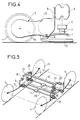
- Figure 4 we recognize a wheel 4 of the bogie, its articulation arm 5 visible by the branch 51, the elastic articulation 6 of the arm on the chassis 1.
- the frame 1 supports the cross-member 10 by means of the elastic block 11.
- the articulation arms 5 can support an electromagnetic pad 32 by file of rails.
- the bogie according to the invention makes it possible to design a particularly advantageous arrangement for ensuring the vertical suspension.
- This arrangement is shown in Figure 5 where the same references as in the previous figures represent the same elements.
- the load cross member 10 is integrated into the additional suspension of leveling to constitute midpoints with complementary suspension springs 81 whatever their nature.
- This arrangement makes it possible to balance the load cross member itself disposed on the transverse suspension blocks 11, and to transmit the drive forces elastically by the suspension itself.
- the references 13 designate the elements of the crossmember intended to serve as midpoints for the complementary suspension springs.
- FIG. 6 which is a detailed view of the bogie shown diagrammatically in FIG. 5, these elements are designated by the references 130.
- These elements can be metal studs attached to the load cross member.
- the console 91 on which a part of the suspension member 81 is fixed, is otherwise arranged on the motor 20.
- the additional suspension members are jacks 82 exerting their action between the studs 131 attached to the load cross member and the brackets 92 integral with the motors.
- the load cross member 10 is an airtight container comprising a lower face 61 integral with the transverse suspension blocks 11, an upper face 62 supporting the body, two lateral faces 63 and 64, each having a central hole and two membranes 65 and 66 pierced with a central hole and forming pneumatic cushions.
- the membranes 65 and 66 are fixed in their centers to two tubular supports 71 and 72 fixed respectively on the consoles 93 of the traction motors by their bottom 73 and 74.
- the membranes 65 and 66 are hermetically connected and respectively to the upper 62 and lower faces 61 by fasteners 67 shown by axes.
- the box includes a device making it possible to obtain inside a variable pressure proportional to the spacing between the consoles.
Claims (14)
- Drehgestell mit angetriebenen, unabhängigen Rädern für Schienenfahrzeuge, mit einem den Kasten des Fahrzeugs tragenden Querchassis (1), wobei die Räder (4) mit dem Chassis durch Arme (5) verbunden sind, die am Chassis durch elastische Gelenke (6) angelenkt sind, wobei jeder Arm einen Fahrmotor (20) trägt, dadurch gekennzeichnet, daß jeder Motor relativ zu dem von ihm angetriebenen Rad achsmäßig versetzt ist, und daß jeder Arm (5) ein Kraftübertragungsgehäuse zwischen dem Motor (20), den er trägt, und dem entsprechenden Rad (4) bildet.
- Drehgestell nach Anspruch 1, dadurch gekennzeichnet, daß jeder Arm (5) aus einer Gabel, in der ein Rad (4) dreht, und aus einem Sattel besteht, der als Träger eines Fahrmotors (20) dient, wobei die Gabel zwei Schenkel (51, 52) aufweist, die durch einen Endsteg (53) miteinander verbunden sind.
- Drehgestell nach Anspruch 2, dadurch gekennzeichnet, daß einer der Schenkel (51) eines Arms (5) das Kraftübertragungsgehäuse bildet.
- Drehgestell nach einem beliebigen der Ansprüche 1 bis 3, dadurch gekennzeichnet, daß jedes elastische Gelenk (6) aus einer Achse besteht, die in Lagern (54, 55, 31) gefaßt ist, die von dem entsprechenden Arm (5) und dem Chassis (1) getragen werden.
- Drehgestell nach einem beliebigen der Ansprüche 1 bis 4, dadurch gekennzeichnet, daß die Arme (5) Stützen (9) tragen, wobei Vertikalaufhängungseinrichtungen (7, 8) zwischen den Stützen befestigt sind, die auf einer gleichen Seite des Drehgestells angeordnet sind.
- Drehgestell nach Anspruch 5, dadurch gekennzeichnet, daß die Vertikalaufhängungseinrichtungen ein Nivellierzusatz-Aufhängungsglied (8) und ggf. ein Leergewichtsaufhängungsglied (7) des Fahrzeugs aufweisen.
- Drehgestell nach Anspruch 5, dadurch gekennzeichnet, daß die zwischen den Stützen befestigten Vertikalaufhängungseinrichtungen ein Nivellierzusatzaufhängungsglied (8) aufweisen und daß ein Torsionsstab (70) zwischen einem Arm (5) und dem Chassis (1) befestigt ist und als Leergewichtaufhängungsglied des Fahrzeugs dient.
- Drehgestell nach einem beliebigen der Ansprüche 5 bis 7, dadurch gekennzeichnet, daß die Stützen (9) auf den Armen (5) über die Fahrmotoren (20) befestigt sind.
- Drehgestell nach einem beliebigen der Ansprüche 1 bis 8, dadurch gekennzeichnet, daß ein Lastquerträger (10), der zum Tragen des Kastens des Fahrzeugs bestimmt ist, über elastische Einrichtungen (11) auf dem Chassis (1) befestigt ist.
- Drehgestell nach Anspruch 9, dadurch gekennzeichnet, daß Vertikalaufhängungseinrichtungen zwischen den Stützen (9) befestigt sind, die von den Armen (5) getragen und auf einer gleichen Seite des Drehgestells angeordnet sind, und daß der Lastquerträger (10) für die Vertikalaufhängungseinrichtungen (81) einen Mittenpunkt bildet.
- Drehgestell nach Anspruch 9, dadurch gekennzeichnet, daß der Lastquerträger (10) ein hermetisch geschlossener Kastenträger ist, der eine pneumatische Aufhängung bildet und als Nivellierzusatzaufhängungsglied dient, wobei sich der Kastenträger zwischen Stützen (93) erstreckt, die von den Armen (5) getragen werden und die seitlich auf einer gleichen Seite des Drehgestells angeordnet sind.
- Drehgestell nach Anspruch 11, dadurch gekennzeichnet, daß der Kastenträger innere Anschläge (69) aufweist, die zwischen zwei seitlichen Stützen (93) die Einhaltung eines Mindestabstands bewirken.
- Drehgestell nach einem der Ansprüche 11 oder 12, dadurch gekennzeichnet, daß der Kastenträger äußere Anschläge (75) aufweist, die zwischen zwei seitlichen Stützen (93) die Einhaltung eines Höchstabstands bewirken.
- Drehgestell nach einem beliebigen der Ansprüche 11 bis 13, dadurch gekennzeichnet, daß ein Aufhängungsglied (7) zum Tragen des Leergewichts des Fahrzeugs zwischen zwei seitlichen Stützen (93) angeordnet ist.
Applications Claiming Priority (2)
| Application Number | Priority Date | Filing Date | Title |
|---|---|---|---|
| FR9008545 | 1990-07-05 | ||
| FR9008545A FR2664222B1 (fr) | 1990-07-05 | 1990-07-05 | Bogie a roues independantes motorisees pour vehicule ferroviaire. |
Publications (2)
| Publication Number | Publication Date |
|---|---|
| EP0465346A1 EP0465346A1 (de) | 1992-01-08 |
| EP0465346B1 true EP0465346B1 (de) | 1994-09-14 |
Family
ID=9398395
Family Applications (1)
| Application Number | Title | Priority Date | Filing Date |
|---|---|---|---|
| EP91401810A Expired - Lifetime EP0465346B1 (de) | 1990-07-05 | 1991-07-02 | Drehgestell mit angetriebenen Losrädern für Schienenfahrzeuge |
Country Status (8)
| Country | Link |
|---|---|
| US (1) | US5181473A (de) |
| EP (1) | EP0465346B1 (de) |
| AT (1) | ATE111401T1 (de) |
| CA (1) | CA2046204C (de) |
| DE (1) | DE69103979T2 (de) |
| DK (1) | DK0465346T3 (de) |
| ES (1) | ES2064058T3 (de) |
| FR (1) | FR2664222B1 (de) |
Families Citing this family (25)
| Publication number | Priority date | Publication date | Assignee | Title |
|---|---|---|---|---|
| DE4136926A1 (de) * | 1991-11-11 | 1993-05-13 | Abb Henschel Waggon Union | Fahrwerk fuer niederflurbahnen |
| IT1256529B (it) * | 1992-02-24 | 1995-12-07 | Fiat Ferroviaria Spa | Carrello motore per un veicolo su rotaie. |
| IT1257195B (it) * | 1992-05-26 | 1996-01-10 | Carrello per veicoli ferrotranviari con motori di trazione e riduttorisospesi al telaio. | |
| ES2078137B1 (es) * | 1992-09-30 | 1996-08-16 | Invastesa | Bogies para vehiculos ferroviarios con separacion variable entre ruedas. |
| GB9410479D0 (en) * | 1994-05-25 | 1994-07-13 | Abb Transportation Ltd | Rail vehicle bogies |
| DE4446043C1 (de) * | 1994-12-22 | 1996-03-07 | Siemens Ag | Fahrwerk für Schienenfahrzeuge |
| AT405734B (de) * | 1996-12-05 | 1999-11-25 | Siemens Sgp Verkehrstech Gmbh | Fahrwerk für einen gliederzug |
| US6092468A (en) * | 1998-03-23 | 2000-07-25 | Daimlerchrysler Ag | Torque controlled mechanism for moving and steering a transit vehicle |
| DE19819467A1 (de) * | 1998-04-30 | 1999-11-11 | Zahnradfabrik Friedrichshafen | Drehgestell für Schienenfahrzeuge |
| ES2170619B1 (es) * | 1999-11-18 | 2003-12-16 | Talgo Patentes | Disposicion de traccion diseminada aplicada a rodaduras ferroviarias monoeje equipadas con ruedas independientes. |
| FR2822780B1 (fr) * | 2001-04-02 | 2003-05-16 | Alstom | Bogie pour vehicules ferroviaires a roues a ecartement variable |
| FR2826328B1 (fr) * | 2001-06-26 | 2003-08-29 | Alstom | Bogie moteur pour vehicule ferroviaire a plancher bas integral |
| DE102007013050B4 (de) * | 2007-03-19 | 2011-05-12 | Siemens Ag | Fahrwerk für ein Schienenfahrzeug |
| FR2946307B1 (fr) * | 2009-06-05 | 2011-08-05 | Alstom Transport Sa | Bogie moteur de vehicule ferroviaire comprenant un moteur semi-suspendu |
| FR2946308B1 (fr) * | 2009-06-05 | 2011-08-05 | Alstom Transport Sa | Bogie de vehicule ferroviaire articule |
| DE102009051773B4 (de) * | 2009-11-04 | 2015-09-03 | Michael Reutter | Neugestaltung einer Eisenbahnachse ohne Antrieb |
| EP2500226A1 (de) * | 2011-03-16 | 2012-09-19 | Bombardier Transportation GmbH | Fahrgestell für ein Schienenfahrzeug mit Motoraufhängung mit Querentkopplung |
| CN113815393A (zh) | 2016-05-06 | 2021-12-21 | 艾里逊变速箱公司 | 具有电动机的车桥总成 |
| CN108146453A (zh) * | 2016-12-05 | 2018-06-12 | 中车大同电力机车有限公司 | 一种低地板有轨电车转向架驱动单元 |
| CN108146461B (zh) * | 2016-12-05 | 2019-06-04 | 中车大同电力机车有限公司 | 一种低地板有轨电车动力车转向架 |
| USD883864S1 (en) | 2018-05-10 | 2020-05-12 | Allison Transmission, Inc. | Axle assembly |
| USD927578S1 (en) | 2018-09-27 | 2021-08-10 | Allison Transmission, Inc. | Axle assembly |
| FR3088042B1 (fr) * | 2018-11-06 | 2020-11-27 | Alstom Transp Tech | Bogie pour vehicule ferroviaire |
| EP3941795A1 (de) * | 2019-03-22 | 2022-01-26 | Stadler Rail AG | Fahrwerk für ein schienenfahrzeug sowie schienenfahrzeugwagen mit mindestens einem fahrwerk, schienenfahrzeug mit mindestens einem schienenfahrzeugwagen und verfahren zur höheneinstellung eines wagenkastens eines schienenfahrzeugwagens |
| FR3124472A1 (fr) * | 2021-06-28 | 2022-12-30 | Alstom Transport Technologies | Bogie et véhicule ferroviaire associé |
Family Cites Families (7)
| Publication number | Priority date | Publication date | Assignee | Title |
|---|---|---|---|---|
| US1880953A (en) * | 1929-02-13 | 1932-10-04 | Twin Coach Co | Rail car construction |
| GB1307268A (en) * | 1970-08-05 | 1973-02-14 | British Leyland Truck & Bus | Bogie suspensions |
| SE401654B (sv) * | 1976-08-19 | 1978-05-22 | Asea Ab | Luftkylning av elektriska traktionsmotorer pa en boggi vid jernvegsfordon |
| IT1118694B (it) * | 1979-05-24 | 1986-03-03 | Fiat Ricerche | Carrello per veicoli ferroviari |
| GB2088801A (en) * | 1980-12-09 | 1982-06-16 | Gyro Mining Transport Ltd | Powered bogie for a rack rail system |
| US4658734A (en) * | 1985-03-11 | 1987-04-21 | Joseph Mroz | Independent suspension railway bogie |
| IT1228887B (it) * | 1989-02-24 | 1991-07-09 | Socimi | Carrello polifunzionale per veicoli su rotaia |
-
1990
- 1990-07-05 FR FR9008545A patent/FR2664222B1/fr not_active Expired - Fee Related
-
1991
- 1991-07-02 DK DK91401810.6T patent/DK0465346T3/da active
- 1991-07-02 EP EP91401810A patent/EP0465346B1/de not_active Expired - Lifetime
- 1991-07-02 DE DE69103979T patent/DE69103979T2/de not_active Expired - Fee Related
- 1991-07-02 AT AT91401810T patent/ATE111401T1/de not_active IP Right Cessation
- 1991-07-02 ES ES91401810T patent/ES2064058T3/es not_active Expired - Lifetime
- 1991-07-04 CA CA002046204A patent/CA2046204C/fr not_active Expired - Fee Related
- 1991-07-05 US US07/726,095 patent/US5181473A/en not_active Expired - Fee Related
Also Published As
| Publication number | Publication date |
|---|---|
| US5181473A (en) | 1993-01-26 |
| ATE111401T1 (de) | 1994-09-15 |
| DE69103979D1 (de) | 1994-10-20 |
| FR2664222B1 (fr) | 1993-01-15 |
| CA2046204A1 (fr) | 1992-01-06 |
| CA2046204C (fr) | 1997-04-22 |
| FR2664222A1 (fr) | 1992-01-10 |
| ES2064058T3 (es) | 1995-01-16 |
| DE69103979T2 (de) | 1995-01-19 |
| EP0465346A1 (de) | 1992-01-08 |
| DK0465346T3 (da) | 1994-12-27 |
Similar Documents
| Publication | Publication Date | Title |
|---|---|---|
| EP0465346B1 (de) | Drehgestell mit angetriebenen Losrädern für Schienenfahrzeuge | |
| EP2258597B1 (de) | Fahrwerk für Schienenfahrzeug | |
| EP2142412B1 (de) | Drehgestell für schienenfahrzeug | |
| EP2258596B1 (de) | Fahrzeugtriebdrehgestell | |
| EP3034375B1 (de) | Motorisiertes drehgestell für ein schienenfahrzeug mit niederflureinstieg | |
| EP2134583B1 (de) | Primäraufhängung für ein drehgestell eines schienenfahrzeugs | |
| EP3650304B1 (de) | Drehgestell für schienenfahrzeug | |
| WO2008125500A2 (fr) | Bogie pour vehicule ferroviaire | |
| FR2464864A1 (fr) | Perfectionnements pour suspensions de voitures de chemin de fer | |
| EP3222485B1 (de) | Schienenfahrzeugdrehgestell, das eine versetzte primäre federungsvorrichtung umfasst | |
| FR2822780A1 (fr) | Bogie pour vehicules ferroviaires a roues a ecartement variable | |
| EP3222486B1 (de) | Schienenfahrzeugdrehgestell, das ein abgesenktes fahrgestell umfasst | |
| WO1998015445A1 (fr) | Chassis de bogie articule et bogie articule comportant un tel chassis | |
| EP0277059B1 (de) | Schienenfahrzeug mit Lastverteilung auf die vier bezüglich des Aufbaus einstellbaren Achsen | |
| FR2958906A1 (fr) | Bogie moteur | |
| EP0829413A2 (de) | Lenkbares Drehgestell | |
| EP3042821B1 (de) | Drehgestell, das eine zentralisierte primärfederung umfasst | |
| EP1712442B1 (de) | Vorrichtung zur Aufhängung eines Motors an einem Drehgestellrahmen | |
| EP0109910B1 (de) | Eisenbahnwagen-Drehgestell | |
| EP3854655B1 (de) | Drehgestell für ein fahrzeug mit unabhängigen rädern und entsprechendes fahrzeug | |
| EP4019366A1 (de) | Aufhängung für schienenfahrzeug mit tragachsen von orientierbaren rädern | |
| FR3121651A1 (fr) | Bogie moteur de véhicule ferroviaire | |
| BE526087A (de) | ||
| FR2615467A1 (fr) | Suspension pour bogie moteur a essieu unique orientable | |
| BE620784A (de) |
Legal Events
| Date | Code | Title | Description |
|---|---|---|---|
| PUAI | Public reference made under article 153(3) epc to a published international application that has entered the european phase |
Free format text: ORIGINAL CODE: 0009012 |
|
| AK | Designated contracting states |
Kind code of ref document: A1 Designated state(s): AT BE CH DE DK ES FR GB IT LI NL SE |
|
| 17P | Request for examination filed |
Effective date: 19920629 |
|
| 17Q | First examination report despatched |
Effective date: 19931011 |
|
| GRAA | (expected) grant |
Free format text: ORIGINAL CODE: 0009210 |
|
| AK | Designated contracting states |
Kind code of ref document: B1 Designated state(s): AT BE CH DE DK ES FR GB IT LI NL SE |
|
| REF | Corresponds to: |
Ref document number: 111401 Country of ref document: AT Date of ref document: 19940915 Kind code of ref document: T |
|
| REF | Corresponds to: |
Ref document number: 69103979 Country of ref document: DE Date of ref document: 19941020 |
|
| GBT | Gb: translation of ep patent filed (gb section 77(6)(a)/1977) |
Effective date: 19941006 |
|
| ITF | It: translation for a ep patent filed |
Owner name: JACOBACCI CASETTA & PERANI S.P.A. |
|
| REG | Reference to a national code |
Ref country code: DK Ref legal event code: T3 |
|
| REG | Reference to a national code |
Ref country code: ES Ref legal event code: FG2A Ref document number: 2064058 Country of ref document: ES Kind code of ref document: T3 |
|
| EAL | Se: european patent in force in sweden |
Ref document number: 91401810.6 |
|
| PLBE | No opposition filed within time limit |
Free format text: ORIGINAL CODE: 0009261 |
|
| STAA | Information on the status of an ep patent application or granted ep patent |
Free format text: STATUS: NO OPPOSITION FILED WITHIN TIME LIMIT |
|
| 26N | No opposition filed | ||
| PGFP | Annual fee paid to national office [announced via postgrant information from national office to epo] |
Ref country code: GB Payment date: 19970616 Year of fee payment: 7 |
|
| PGFP | Annual fee paid to national office [announced via postgrant information from national office to epo] |
Ref country code: DE Payment date: 19970620 Year of fee payment: 7 |
|
| PGFP | Annual fee paid to national office [announced via postgrant information from national office to epo] |
Ref country code: FR Payment date: 19970622 Year of fee payment: 7 |
|
| PGFP | Annual fee paid to national office [announced via postgrant information from national office to epo] |
Ref country code: SE Payment date: 19970623 Year of fee payment: 7 Ref country code: DK Payment date: 19970623 Year of fee payment: 7 |
|
| PGFP | Annual fee paid to national office [announced via postgrant information from national office to epo] |
Ref country code: BE Payment date: 19970624 Year of fee payment: 7 |
|
| PGFP | Annual fee paid to national office [announced via postgrant information from national office to epo] |
Ref country code: CH Payment date: 19970627 Year of fee payment: 7 |
|
| PGFP | Annual fee paid to national office [announced via postgrant information from national office to epo] |
Ref country code: NL Payment date: 19970630 Year of fee payment: 7 Ref country code: AT Payment date: 19970630 Year of fee payment: 7 |
|
| PGFP | Annual fee paid to national office [announced via postgrant information from national office to epo] |
Ref country code: ES Payment date: 19970718 Year of fee payment: 7 |
|
| PG25 | Lapsed in a contracting state [announced via postgrant information from national office to epo] |
Ref country code: GB Free format text: LAPSE BECAUSE OF NON-PAYMENT OF DUE FEES Effective date: 19980702 Ref country code: AT Free format text: LAPSE BECAUSE OF NON-PAYMENT OF DUE FEES Effective date: 19980702 |
|
| PG25 | Lapsed in a contracting state [announced via postgrant information from national office to epo] |
Ref country code: SE Free format text: LAPSE BECAUSE OF NON-PAYMENT OF DUE FEES Effective date: 19980703 Ref country code: ES Free format text: LAPSE BECAUSE OF THE APPLICANT RENOUNCES Effective date: 19980703 |
|
| PG25 | Lapsed in a contracting state [announced via postgrant information from national office to epo] |
Ref country code: LI Free format text: LAPSE BECAUSE OF NON-PAYMENT OF DUE FEES Effective date: 19980731 Ref country code: DK Free format text: LAPSE BECAUSE OF NON-PAYMENT OF DUE FEES Effective date: 19980731 Ref country code: CH Free format text: LAPSE BECAUSE OF NON-PAYMENT OF DUE FEES Effective date: 19980731 Ref country code: BE Free format text: LAPSE BECAUSE OF NON-PAYMENT OF DUE FEES Effective date: 19980731 |
|
| BERE | Be: lapsed |
Owner name: S.A. GEC ALSTHOM Effective date: 19980731 |
|
| PG25 | Lapsed in a contracting state [announced via postgrant information from national office to epo] |
Ref country code: NL Free format text: LAPSE BECAUSE OF NON-PAYMENT OF DUE FEES Effective date: 19990201 |
|
| GBPC | Gb: european patent ceased through non-payment of renewal fee |
Effective date: 19980702 |
|
| REG | Reference to a national code |
Ref country code: CH Ref legal event code: PL |
|
| EUG | Se: european patent has lapsed |
Ref document number: 91401810.6 |
|
| PG25 | Lapsed in a contracting state [announced via postgrant information from national office to epo] |
Ref country code: FR Free format text: LAPSE BECAUSE OF NON-PAYMENT OF DUE FEES Effective date: 19990331 |
|
| NLV4 | Nl: lapsed or anulled due to non-payment of the annual fee |
Effective date: 19990201 |
|
| PG25 | Lapsed in a contracting state [announced via postgrant information from national office to epo] |
Ref country code: DE Free format text: LAPSE BECAUSE OF NON-PAYMENT OF DUE FEES Effective date: 19990501 |
|
| REG | Reference to a national code |
Ref country code: FR Ref legal event code: ST |
|
| REG | Reference to a national code |
Ref country code: DK Ref legal event code: EBP |
|
| REG | Reference to a national code |
Ref country code: ES Ref legal event code: FD2A Effective date: 20001009 |
|
| PG25 | Lapsed in a contracting state [announced via postgrant information from national office to epo] |
Ref country code: IT Free format text: LAPSE BECAUSE OF NON-PAYMENT OF DUE FEES;WARNING: LAPSES OF ITALIAN PATENTS WITH EFFECTIVE DATE BEFORE 2007 MAY HAVE OCCURRED AT ANY TIME BEFORE 2007. THE CORRECT EFFECTIVE DATE MAY BE DIFFERENT FROM THE ONE RECORDED. Effective date: 20050702 |