EP0465346B1 - Bogie with independently driven wheels for a railway vehicle - Google Patents
Bogie with independently driven wheels for a railway vehicle Download PDFInfo
- Publication number
- EP0465346B1 EP0465346B1 EP91401810A EP91401810A EP0465346B1 EP 0465346 B1 EP0465346 B1 EP 0465346B1 EP 91401810 A EP91401810 A EP 91401810A EP 91401810 A EP91401810 A EP 91401810A EP 0465346 B1 EP0465346 B1 EP 0465346B1
- Authority
- EP
- European Patent Office
- Prior art keywords
- bogey
- brackets
- chassis
- arm
- bogey according
- Prior art date
- Legal status (The legal status is an assumption and is not a legal conclusion. Google has not performed a legal analysis and makes no representation as to the accuracy of the status listed.)
- Expired - Lifetime
Links
- 239000000725 suspension Substances 0.000 claims description 44
- 230000005540 biological transmission Effects 0.000 claims description 8
- 125000006850 spacer group Chemical group 0.000 claims description 5
- 239000002184 metal Substances 0.000 description 6
- 230000000295 complement effect Effects 0.000 description 3
- 239000012528 membrane Substances 0.000 description 3
- 208000031968 Cadaver Diseases 0.000 description 1
- 235000015842 Hesperis Nutrition 0.000 description 1
- 235000012633 Iberis amara Nutrition 0.000 description 1
- 240000008042 Zea mays Species 0.000 description 1
- 239000000853 adhesive Substances 0.000 description 1
- 230000001070 adhesive effect Effects 0.000 description 1
- 230000000712 assembly Effects 0.000 description 1
- 238000000429 assembly Methods 0.000 description 1
- 238000010586 diagram Methods 0.000 description 1
- 238000005516 engineering process Methods 0.000 description 1
- 230000002349 favourable effect Effects 0.000 description 1
- 239000012530 fluid Substances 0.000 description 1
- 238000011084 recovery Methods 0.000 description 1
- 230000000284 resting effect Effects 0.000 description 1
- 238000000926 separation method Methods 0.000 description 1
Images


Classifications
-
- B—PERFORMING OPERATIONS; TRANSPORTING
- B61—RAILWAYS
- B61F—RAIL VEHICLE SUSPENSIONS, e.g. UNDERFRAMES, BOGIES OR ARRANGEMENTS OF WHEEL AXLES; RAIL VEHICLES FOR USE ON TRACKS OF DIFFERENT WIDTH; PREVENTING DERAILING OF RAIL VEHICLES; WHEEL GUARDS, OBSTRUCTION REMOVERS OR THE LIKE FOR RAIL VEHICLES
- B61F3/00—Types of bogies
- B61F3/02—Types of bogies with more than one axle
- B61F3/04—Types of bogies with more than one axle with driven axles or wheels
-
- B—PERFORMING OPERATIONS; TRANSPORTING
- B61—RAILWAYS
- B61D—BODY DETAILS OR KINDS OF RAILWAY VEHICLES
- B61D13/00—Tramway vehicles
-
- B—PERFORMING OPERATIONS; TRANSPORTING
- B61—RAILWAYS
- B61F—RAIL VEHICLE SUSPENSIONS, e.g. UNDERFRAMES, BOGIES OR ARRANGEMENTS OF WHEEL AXLES; RAIL VEHICLES FOR USE ON TRACKS OF DIFFERENT WIDTH; PREVENTING DERAILING OF RAIL VEHICLES; WHEEL GUARDS, OBSTRUCTION REMOVERS OR THE LIKE FOR RAIL VEHICLES
- B61F3/00—Types of bogies
- B61F3/16—Types of bogies with a separate axle for each wheel
Definitions
- This bogie is mainly constituted by a supporting chassis supporting the body.
- the connections between the wheels and the chassis by articulated arms are obtained by elastic joints according to an arrangement well known in automotive and railway technology.
- these articulated arms (or pulled arms) have the particularity of being able to constitute the transmission casings themselves and of supporting the traction motor which is thus completely suspended.
- FIG. 1 shows schematically a bogie with four independent wheels according to the invention.
- This bogie comprises a transverse supporting frame 1 consisting of a cross member 2 terminated, at each end, by a horizontal beam 3 and perpendicular to the cross member giving the frame the general shape in capital letter I.
- the connections between the wheels 4 and the chassis 1 are produced by articulated arms 5.
- An elastic articulation 6 provides the connection between each arm 5 and the corresponding end of a spar 3.
- the arms articulated 5 are intended to support the traction motors of the wheels. They also constitute the transmission housings between the motors and the wheels. The motors are thus completely suspended.
- the invention makes it possible to design a particular suspension for the bogie. It is indeed possible to functionally separate the actual suspension taking up the tare weight of the vehicle and the additional leveling suspension subjected to the variable load of the vehicle loaded by the travelers.
- This separate suspension is achieved by members which, although different, may be located close to each other.
- the tare weight of the vehicle is taken up by the suspension members 7 which can be helical springs, torsion bars or rubber-metal assemblies.
- the additional leveling suspension is provided by a suspension member 8.
- the suspension members 7 and 8 can be located horizontally and laterally between vertical consoles 9 secured to the articulation arms 5 near the articulations 3. As shown in the figure 1, these suspension members are placed parallel to the rails.
- the drive and the rotation of the body can be ensured by conventional means such as longitudinal connecting rods and an orientable pivot crown.
- FIG 2 is a perspective view of a hinge arm 5.
- the fork comprises a first branch 51 and a second branch 52 connected by an end spacer 53.
- the two branches 51 and 52 are of different dimensions.
- the branch 51 occupies a larger volume than the branch 52 because it is intended to contain the transmission members between the motor and the wheel.
- the branches 51 and 52 respectively comprise bearings 54 and 55 located on the side of the spacer 53.
- the articulation of the arm on the chassis can be done by means of an axis passing through the bearings 54 and 55 as well as a bearing 31 located at the end of the side member 3 of the chassis.
- the articulation bearings can advantageously be produced by rubber-metal parts capable of resisting elastically the forces driving the arm during the application of the traction and braking torques, and the transverse forces due to the guiding of the wheel. on the way.
- the fork rests on the two spindles of the wheel, which is engaged in the fork, by means of bearings.
- the free ends of the arms 51 and 52 can be separated from the rest of the arm according to joint planes 56 and 57 passing through the axis of the wheel so as to be able to mount and dismount the latter.
- the cradle is the part that supports the traction motor. It is located near the joint and braces the two branches. It can be constituted by a metal plate disposed between the two branches or by spacers, one of which can be the end spacer 53.
- the engine can be fixed by screws.
- the motor will be fixed on the cradle so that the axis of the motor can drive a set of pinions located inside the branch 51 which then serves as a casing.
- the motor will advantageously be arranged so that its axis is horizontal and transverse relative to the wheel.
- FIG 3 there is shown a part of a bogie comprising a train of wheels 4 placed in the housings formed by the articulation arms 5.
- the arms 5 are articulated to the carrying frame 1 by elastic joints not shown.
- the axis 21 of a motor 20 rotates, by the through a set of pinions 22, the spindle 42 of the corresponding wheel 4.
- Each torsion bar 70 is fixed on one side to a projection 12 from the central part of the chassis and on the other side to an articulation arm 5.
- the torsion bars 70 serve as tare suspension members of the vehicle and therefore play the same role as the members referenced 7 on the Figure 1.
- the additional suspension members 8, shown as pneumatic elements, are placed between supports integral with the suspension arms. These members 8 can also be formed by other elastic elements with variable flexibility such as rubber and metal blocks, hydraulic or hydro-pneumatic cylinders.
- the supports of these bodies can be consoles as is briefly shown in Figure 1 where they can be formed by the traction motors themselves.
- This arrangement of functionally separate suspensions results in a small overall height.
- it allows a more favorable dimensioning of the components as well as the associated fluid sources since the additional suspension only supports part of the total load.
- the braking system can comprise disks 40 fixed on the rockets 43 of the wheels 4.
- Calipers 41 supporting the actuators of the brake shoes, can be fixed on the traction motors themselves.
- the braking assembly itself is completed by an electromagnetic braking pad resting on the two arms pulled between the wheels of the same file of rails.
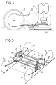
- Figure 4 we recognize a wheel 4 of the bogie, its articulation arm 5 visible by the branch 51, the elastic articulation 6 of the arm on the chassis 1.
- the frame 1 supports the cross-member 10 by means of the elastic block 11.
- the articulation arms 5 can support an electromagnetic pad 32 by file of rails.
- the bogie according to the invention makes it possible to design a particularly advantageous arrangement for ensuring the vertical suspension.
- This arrangement is shown in Figure 5 where the same references as in the previous figures represent the same elements.
- the load cross member 10 is integrated into the additional suspension of leveling to constitute midpoints with complementary suspension springs 81 whatever their nature.
- This arrangement makes it possible to balance the load cross member itself disposed on the transverse suspension blocks 11, and to transmit the drive forces elastically by the suspension itself.
- the references 13 designate the elements of the crossmember intended to serve as midpoints for the complementary suspension springs.
- FIG. 6 which is a detailed view of the bogie shown diagrammatically in FIG. 5, these elements are designated by the references 130.
- These elements can be metal studs attached to the load cross member.
- the console 91 on which a part of the suspension member 81 is fixed, is otherwise arranged on the motor 20.
- the additional suspension members are jacks 82 exerting their action between the studs 131 attached to the load cross member and the brackets 92 integral with the motors.
- the load cross member 10 is an airtight container comprising a lower face 61 integral with the transverse suspension blocks 11, an upper face 62 supporting the body, two lateral faces 63 and 64, each having a central hole and two membranes 65 and 66 pierced with a central hole and forming pneumatic cushions.
- the membranes 65 and 66 are fixed in their centers to two tubular supports 71 and 72 fixed respectively on the consoles 93 of the traction motors by their bottom 73 and 74.
- the membranes 65 and 66 are hermetically connected and respectively to the upper 62 and lower faces 61 by fasteners 67 shown by axes.
- the box includes a device making it possible to obtain inside a variable pressure proportional to the spacing between the consoles.
Abstract
Description
L'invention concerne un bogie à roues indépendantes motorisées, destiné aussi bien aux véhicules ferroviaires des transports urbains qu'aux trains à grande vitesse.The invention relates to a bogie with independent motorized wheels, intended both for rail vehicles of urban transport and for high speed trains.
La conception d'un bogie à roues indépendantes présente de nombreux avantages, notamment dans les domaines :
- des vitesses élevées de circulation car la stabilité d'un tel bogie, caractérisée par sa vitesse critique, est très élevée ;
- des véhicules de transport urbain à plancher surbaissé car il n'y a pas alors d'arbre d'essieu qui puisse interférer avec le passage du plancher dont le niveau par rapport aux rails est souhaité le plus bas possible.
- high circulation speeds because the stability of such a bogie, characterized by its critical speed, is very high;
- urban transport vehicles with a lowered floor because there is then no axle shaft which can interfere with the passage of the floor whose level with respect to the rails is desired as low as possible.
De tels bogies à roues indépendantes ont déjà été réalisés dans le cas de bogies porteurs.Such bogies with independent wheels have already been produced in the case of load-bearing bogies.
Concernant la réalisation d'un bogie moteur à roues indépendantes, quelques conceptions de motorisation ont déjà été proposées, notamment avec un moteur entraînant chaque roue. Cependant, ces solutions ne sont pas satisfaisantes car elles portent :
- soit sur la motorisation d'un seul train de roues limitant par conséquence la masse adhérente du véhicule,
- soit sur un bogie avec quatre roues motorisées mais dans ce cas l'ensemble motoréducteur n'est pas suspendu et fait corps avec la roue correspondante.
- either on the motorization of a single set of wheels consequently limiting the adhesive mass of the vehicle,
- either on a bogie with four motorized wheels but in this case the gearmotor assembly is not suspended and is integral with the corresponding wheel.
Afin de pallier ces inconvénients, on propose de réaliser une transmission avec un moteur entièrement suspendu, la motorisation complète du bogie et une suspension de bogie nivelée, de faible encombrement en hauteur comme il se doit dans un bogie pour véhicule de transport de voyageurs.In order to overcome these drawbacks, it is proposed to produce a transmission with a fully suspended engine, the complete motorization of the bogie and a leveled bogie suspension, of small overall height as it should be in a bogie for a passenger transport vehicle.
Ce bogie est constitué principalement par un châssis porteur supportant la caisse. Les liaisons entre les roues et le châssis par des bras articulés sont obtenues par des articulations élastiques selon une disposition bien connue en technique automobile et ferroviaire. Cependant, ces bras articulés (ou bras tirés) ont la particularité de pouvoir constituer eux-mêmes les carters de transmission et de supporter le moteur de traction qui est ainsi complètement suspendu.This bogie is mainly constituted by a supporting chassis supporting the body. The connections between the wheels and the chassis by articulated arms are obtained by elastic joints according to an arrangement well known in automotive and railway technology. However, these articulated arms (or pulled arms) have the particularity of being able to constitute the transmission casings themselves and of supporting the traction motor which is thus completely suspended.
L'invention a donc pour objet un bogie à roues indépendantes motorisées, comportant un châssis transversal porteur, les roues étant reliées au châssis par des bras articulés au châssis grâce à des articulations élastiques, chaque bras supportant un moteur de traction, caractérisé en ce que, chaque moteur étant désaxé par rapport à la roue qu'il entraîne, chaque bras constitue un carter de transmission entre le moteur qu'il supporte et la roue correspondante.The invention therefore relates to a bogie with independent motorized wheels, comprising a transverse load-bearing chassis, the wheels being connected to the chassis by arms articulated to the chassis by means of elastic articulations, each arm supporting a traction motor, characterized in that , each motor being offset with respect to the wheel which it drives, each arm constitutes a transmission casing between the motor which it supports and the corresponding wheel.
L'invention sera mieux comprise et d'autres avantages apparaîtront à la lecture de la description qui va suivre, donnée à titre non limitatif, accompagnée des dessins annexés parmi lesquels :
- la figure 1 représente le schéma de principe d'un bogie à roues indépendantes motorisées selon l'invention,
- la figure 2 représente un bras d'articulation du bogie selon l'invention,
- la figure 3 représente, vue de dessus, une partie de bogie selon l'invention,
- la figure 4 est une vue du côté externe d'une partie du bogie selon l'invention,
- la figure 5 est une vue schématique d'une variante de bogie selon l'invention,
- la figure 6 est une vue de détail de la variante de réalisation schématisée à la figure 5,
- la figure 7 est une autre vue de détail de la variante de réalisation schématisée à la figure 5,
- la figure 8 représente un détail de bogie selon l'invention et utilisant un système de suspension pneumatique particulier.
- FIG. 1 represents the block diagram of a bogie with independent motorized wheels according to the invention,
- FIG. 2 represents an articulation arm of the bogie according to the invention,
- FIG. 3 represents, seen from above, a part of a bogie according to the invention,
- FIG. 4 is a view from the external side of a part of the bogie according to the invention,
- FIG. 5 is a schematic view of an alternative bogie according to the invention,
- FIG. 6 is a detailed view of the variant embodiment shown diagrammatically in FIG. 5,
- FIG. 7 is another detailed view of the variant embodiment shown diagrammatically in FIG. 5,
- FIG. 8 represents a detail of a bogie according to the invention and using a particular pneumatic suspension system.
La figure 1 représente schématiquement un bogie à quatre roues indépendantes selon l'invention. Ce bogie comprend un châssis transversal porteur 1 constitué d'une traverse 2 terminée, à chaque extrémité, par un longeron 3 horizontal et perpendiculaire à la traverse donnant au châssis la forme générale en I majuscule. Les liaisons entre les roues 4 et le châssis 1 sont réalisées par des bras articulés 5. Une articulation élastique 6 assure la liaison entre chaque bras 5 et l'extrémité correspondante d'un longeron 3. Les bras articulés 5 sont destinés à supporter les moteurs de traction des roues. Ils constituent également les carters de transmission entre les moteurs et les roues. Les moteurs sont ainsi complètement suspendus.Figure 1 shows schematically a bogie with four independent wheels according to the invention. This bogie comprises a transverse supporting frame 1 consisting of a
L'invention permet de concevoir une suspension particulière pour le bogie. Il est en effet possible de séparer fonctionnellement la suspension proprement dite reprenant la tare du véhicule et la suspension complémentaire de nivellement soumise à la charge variable du véhicule chargé par les voyageurs. Cette suspension séparée est réalisée par des organes qui, bien qu'étant différents, peuvent être situés à proximité l'un de l'autre. La tare du véhicule est reprise par les organes de suspension 7 qui peuvent être des ressorts hélicoïdaux, des barres de torsion ou des ensembles caoutchouc-métal. La suspension complémentaire de nivellement est assurée par un organe de suspension 8. Les organes de suspension 7 et 8 peuvent être situés horizontalement et latéralement entre des consoles verticales 9 solidaires des bras d'articulation 5 à proximité des articulations 3. Comme le montre la figure 1, ces organes de suspension sont placés parallèlement aux rails.The invention makes it possible to design a particular suspension for the bogie. It is indeed possible to functionally separate the actual suspension taking up the tare weight of the vehicle and the additional leveling suspension subjected to the variable load of the vehicle loaded by the travelers. This separate suspension is achieved by members which, although different, may be located close to each other. The tare weight of the vehicle is taken up by the suspension members 7 which can be helical springs, torsion bars or rubber-metal assemblies. The additional leveling suspension is provided by a
Une traverse de charge 10, solidaire de la caisse, repose sur le châssis 1 par l'intermédiaire, par exemple, de deux blocs de caoutchouc-métal lamellé 11. Ces blocs 11 permettent, selon une disposition classique, la suspension transversale du véhicule.A
L'entraînement et la rotation de la caisse peuvent être assurés par des moyens classiques tels que des bielles longitudinales et une couronne en pivot d'orientation.The drive and the rotation of the body can be ensured by conventional means such as longitudinal connecting rods and an orientable pivot crown.
La figure 2 est une vue en perspective d'un bras d'articulation 5. Le bras d'articulation 5, que l'on peut encore appeler bras motoréducteur puisqu'il sert de carter de transmission entre moteur et roue, est constitué de deux parties solidaires entre elles : une fourche et un berceau.Figure 2 is a perspective view of a
La fourche comprend une première branche 51 et une deuxième branche 52 reliées par une entretoise d'extrémité 53. Les deux branches 51 et 52 sont de dimensions différentes. La branche 51 occupe un volume plus important que la branche 52 parce qu'elle est destinée à contenir les organes de transmission entre moteur et roue. Les branches 51 et 52 comportent respectivement des paliers 54 et 55 situés du côté de l'entretoise 53. L'articulation du bras sur le châssis peut se faire au moyen d'un axe traversant les paliers 54 et 55 ainsi qu'un palier 31 situé à l'extrémité du longeron latéral 3 du châssis.The fork comprises a
Les paliers d'articulation peuvent avantageusement être réalisés par des pièces en caoutchouc-métal susceptibles de résister élastiquement aux efforts d'entraînement du bras lors de l'application des couples de traction et de freinage, et aux efforts transversaux dus au guidage de la roue sur la voie.The articulation bearings can advantageously be produced by rubber-metal parts capable of resisting elastically the forces driving the arm during the application of the traction and braking torques, and the transverse forces due to the guiding of the wheel. on the way.
Du côté opposé à l'articulation, la fourche s'appuie sur les deux fusées de la roue, qui est engagée dans la fourche, par l'intermédiaire de roulements.On the side opposite the articulation, the fork rests on the two spindles of the wheel, which is engaged in the fork, by means of bearings.
Les extrémités libres des branches 51 et 52 peuvent être séparées du reste du bras selon des plans de joint 56 et 57 passant par l'axe de la roue de manière à pouvoir monter et démonter celle-ci.The free ends of the
Le berceau est la partie qui supporte le moteur de traction. Il est situé à proximité de l'articulation et entretoise les deux branches. Il peut être constitué par une plaque métallique disposée entre les deux branches ou par des entretoises dont l'une peut être l'entretoise d'extrémité 53. La fixation du moteur peut être assurée par des vis. Le moteur sera fixé sur le berceau de façon que l'axe du moteur puisse entraîner un jeu de pignons situés à l'intérieur de la branche 51 qui sert alors de carter. Le moteur sera avantageusement disposé de façon que son axe soit horizontal et transversal par rapport à la roue.The cradle is the part that supports the traction motor. It is located near the joint and braces the two branches. It can be constituted by a metal plate disposed between the two branches or by spacers, one of which can be the
A la figure 3, on a représenté une partie d'un bogie comprenant un train de roues 4 placés dans les logements que leur constituent les bras d'articulation 5. Les bras 5 sont articulés au châssis porteur 1 par des articulations élastiques non représentées. Sur cette figure on peut voir les moteurs d'entraînement 20 en position sur les bras 5, des barres de torsion 70, des organes de suspension complémentaire de nivellement 8. L'axe 21 d'un moteur 20 entraîne en rotation, par l'intermédiaire d'un jeu de pignons 22, la fusée 42 de la roue 4 correspondante. Chaque barre de torsion 70 est fixée d'un côté à une saillie 12 de la partie centrale du châssis et de l'autre côté à un bras d'articulation 5. Les barres de torsion 70 servent d'organes de suspension de tare du véhicule et jouent donc le même rôle que les organes référencés 7 sur la figure 1. Les organes de suspension complémentaire 8, représentés en tant qu'éléments pneumatiques, sont placés entre des appuis solidaires des bras de suspension. Ces organes 8 peuvent aussi être consitués par d'autres éléments élastiques à flexibilité variable tels que des blocs de caoutchouc et de métal, des vérins hydrauliques ou hydro-pneumatiques. Les appuis de ces organes peuvent être des consoles comme cela est représenté sommairement à la figure 1 où ils peuvent être constitués par les moteurs de traction eux-mêmes.In Figure 3, there is shown a part of a bogie comprising a train of wheels 4 placed in the housings formed by the
Cette disposition de suspensions séparées fonctionnellement conduit à un faible encombrement en hauteur. De plus, elle permet un dimensionnement plus favorable des composants ainsi que des sources de fluide associées puisque la suspension complémentaire ne supporte qu'une partie de la charge totale.This arrangement of functionally separate suspensions results in a small overall height. In addition, it allows a more favorable dimensioning of the components as well as the associated fluid sources since the additional suspension only supports part of the total load.
Le système de freinage peut comprendre des disques 40 fixés sur les fusées 43 des roues 4. Des étriers 41, supportant les actionneurs des patins de freinage, peuvent être fixés sur les moteurs de traction eux-mêmes. L'ensemble de freinage lui-même est complété par un patin de freinage électromagnétique s'appuyant sur les deux bras tirés situés entre les roues d'une même file de rails.The braking system can comprise
Sur la figure 4 on reconnaît une roue 4 du bogie, son bras d'articulation 5 visible par la branche 51, l'articulation élastique 6 du bras sur le châssis 1. Le moteur 20, caché par la branche 51, supporte la console 9 sur laquelle est fixé une face de l'organe de suspension complémentaire 8. Le châssis 1 supporte la traverse 10 par l'intermédiaire du bloc élastique 11. Les bras d'articulation 5 peuvent supporter un patin électromagnétique 32 par file de rails.In Figure 4 we recognize a wheel 4 of the bogie, its
Le bogie selon l'invention permet de concevoir une disposition particulièrement intéressante pour assurer la suspension verticale. Cette disposition est représentée à la figure 5 où les mêmes références qu'aux figures précédentes représentent les mêmes éléments. La traverse de charge 10 est intégrée à la suspension complémentaire de nivellement pour constituer des points milieux aux ressorts complémentaires de suspension 81 quelle qu'en soit leur nature. Cette disposition permet d'équilibrer la traverse de charge elle-même disposée sur les blocs de suspension transversale 11, et de transmettre élastiquement les efforts d'entraînement par la suspension elle-même. Sur la figure 5, les références 13 désignent les éléments de la traverse destinés à servir de points milieux aux ressorts complémentaires de suspension. Sur la figure 6, qui est une vue de détail du bogie schématisé à la figure 5, ces éléments sont désignés par les références 130. Ces éléments peuvent être des plots métalliques rapportés sur la traverse de charge. On remarque que la console 91, sur laquelle est fixée une partie de l'organe de suspension 81, est disposée autrement sur le moteur 20.The bogie according to the invention makes it possible to design a particularly advantageous arrangement for ensuring the vertical suspension. This arrangement is shown in Figure 5 where the same references as in the previous figures represent the same elements. The
Sur la figure 7, les organes complémentaires de suspension sont des vérins 82 exerçant leur action entre les plots 131 rapportés sur la traverse de charge et les consoles 92 solidaires des moteurs.In FIG. 7, the additional suspension members are
Selon la figure 8, la traverse de charge 10, vue en coupe transversale, est un caisson hermétique comprenant une face inférieure 61 solidaire des blocs de suspension transversale 11, une face supérieure 62 supportant la caisse, deux faces latérales 63 et 64, chacune possédant un trou central et deux membranes 65 et 66 percées d'un trou central et formant coussins pneumatiques. Les membranes 65 et 66 sont fixées en leurs centres à deux supports tubulaires 71 et 72 fixés respectivement sur les consoles 93 des moteurs de traction par leur fond 73 et 74. Les membranes 65 et 66 sont reliées hermétiquement et respectivement aux faces supérieure 62 et inférieure 61 par des éléments de fixation 67 figurés par des axes. Elles sont aussi reliées hermétiquement aux supports tubulaires par des éléments de fixation 68 figurés également par des axes et qui incluent des butées internes 69 imposant une distance minimum entre les consoles 93. Des butées externes 75, solidaires par exemple de la face supérieure 62 et associées à des contre-butées 76 solidaires des fonds 73 et 74, servent à éviter un écartement trop grand des consoles 93. Ces deux types de butées permettent le levage du bogie et la réalisation d'une butée de secours en cas de manque de fluide de suspension. Le volume intérieur à cette structure permet d'intégrer le ressort de suspension de reprise de tare 7, ce qui réduit l'encombrement de l'ensemble. Comme pour un autre organe de suspension pneumatique, le caisson comprend un dispositif permettant d'obtenir à l'intérieur une pression variable proportionnelle à l'écartement entre les consoles.According to FIG. 8, the
Claims (14)
- A rail vehicle bogey having independent motorized wheels, the bogey comprising a transverse chassis (1) carrying the body of the vehicle, the wheels (4) being connected to the chassis by arms (5) hinged to the chassis by means of resilient hinges (6), each arm supporting a traction motor (20), the bogey being characterized in that each motor is offset relative to the wheel which it drives, with each arm (5) constituting a transmission housing between the motor (20) that it supports and the corresponding wheel (4).
- A bogey according to claim 1, characterized in that each arm (5) is constituted by a fork which receives a wheel (4) and by a cradle serving as a support for a traction motor (20), the fork having two branches (51, 52) interconnected by an end spacer (53).
- A bogey according to claim 2, characterized in that the one of the branches (51) of an arm (5) constitutes the transmission housing.
- A bogey according to any one of claims 1 to 3, characterized in that each resilient hinge (6) is constituted by a shaft engaged in bearings (54, 55, 31) supported by the corresponding arm (5) and by the chassis (1).
- A bogey according to any one of claims 1 to 4, characterized in that the arms (5) support brackets (9), with vertical suspension means (7, 8) being fixed between the brackets situated on the same side of the bogey.
- A bogey according to claim 5, characterized in that the vertical suspension means comprise an additional levelling suspension member (8) and optionally a suspension member for the tare weight of the vehicle (7).
- A bogey according to claim 5, characterized in that the vertical suspension means fixed between the brackets comprise an additional levelling suspension member (8), a torsion bar (70) fixed between an arm (5) and the chassis (1) serving as the vehicle tare weight suspension member.
- A bogey according to any one of claims 5 to 7, characterized in that the brackets (9) are fixed to the arms (5) via the traction motors (20).
- A bogey according to any one of claims 1 to 8, characterized in that a load-bearing cross-member (10) for supporting the vehicle body is fixed to the chassis (1) via resilient means (11).
- A bogey according to claim 9, characterized in that the vertical suspension means are fixed between the brackets (9) supported by the arms (5) and situated on the same side of the bogey, and the load-bearing cross-member (10) constitutes a midpoint for the vertical suspension means (81).
- A bogey according to claim 9, characterized in that the load-bearing cross-member (10) is a hermetically sealed box constituting a pneumatic suspension member and serving as an additional levelling suspension member, the box extending between the brackets (93) supported by the arms (5) and situated on the same side of the bogey.
- A bogey according to claim 11, characterized in that the box includes internal abutments (69) imposing a minimum distance between the two side brackets (93).
- A bogey according to claim 11 or 12, characterized in that the box has external abutments (75) imposing a maximum distance between the two side brackets (93).
- A bogey according to any one of claims 11 to 13, characterized in that a suspension member (7) for taking up the vehicle tare weight is placed inside the box, between the two side brackets (93).
Applications Claiming Priority (2)
| Application Number | Priority Date | Filing Date | Title |
|---|---|---|---|
| FR9008545A FR2664222B1 (en) | 1990-07-05 | 1990-07-05 | BOGIE WITH INDEPENDENT MOTORIZED WHEELS FOR RAIL VEHICLE. |
| FR9008545 | 1990-07-05 |
Publications (2)
| Publication Number | Publication Date |
|---|---|
| EP0465346A1 EP0465346A1 (en) | 1992-01-08 |
| EP0465346B1 true EP0465346B1 (en) | 1994-09-14 |
Family
ID=9398395
Family Applications (1)
| Application Number | Title | Priority Date | Filing Date |
|---|---|---|---|
| EP91401810A Expired - Lifetime EP0465346B1 (en) | 1990-07-05 | 1991-07-02 | Bogie with independently driven wheels for a railway vehicle |
Country Status (8)
| Country | Link |
|---|---|
| US (1) | US5181473A (en) |
| EP (1) | EP0465346B1 (en) |
| AT (1) | ATE111401T1 (en) |
| CA (1) | CA2046204C (en) |
| DE (1) | DE69103979T2 (en) |
| DK (1) | DK0465346T3 (en) |
| ES (1) | ES2064058T3 (en) |
| FR (1) | FR2664222B1 (en) |
Families Citing this family (25)
| Publication number | Priority date | Publication date | Assignee | Title |
|---|---|---|---|---|
| DE4136926A1 (en) * | 1991-11-11 | 1993-05-13 | Abb Henschel Waggon Union | CHASSIS FOR LOW-FLOOR RAILWAYS |
| IT1256529B (en) * | 1992-02-24 | 1995-12-07 | Fiat Ferroviaria Spa | MOTOR TROLLEY FOR A VEHICLE ON RAILS. |
| IT1257195B (en) * | 1992-05-26 | 1996-01-10 | TROLLEY FOR RAILWAY VEHICLES WITH TRACTION MOTORS AND GEARBOXES SUSPENDED ON THE FRAME. | |
| ES2078137B1 (en) * | 1992-09-30 | 1996-08-16 | Invastesa | BOGIES FOR RAILWAY VEHICLES WITH VARIABLE SEPARATION BETWEEN WHEELS. |
| GB9410479D0 (en) * | 1994-05-25 | 1994-07-13 | Abb Transportation Ltd | Rail vehicle bogies |
| DE4446043C1 (en) * | 1994-12-22 | 1996-03-07 | Siemens Ag | Electric rail vehicle running chassis |
| AT405734B (en) * | 1996-12-05 | 1999-11-25 | Siemens Sgp Verkehrstech Gmbh | UNDERCARRIAGE FOR A TOWED TRAIN |
| US6092468A (en) * | 1998-03-23 | 2000-07-25 | Daimlerchrysler Ag | Torque controlled mechanism for moving and steering a transit vehicle |
| DE19819467A1 (en) * | 1998-04-30 | 1999-11-11 | Zahnradfabrik Friedrichshafen | Bogie for rail vehicles |
| ES2170619B1 (en) * | 1999-11-18 | 2003-12-16 | Talgo Patentes | DISSEMINED TRACTION PROVISION APPLIED TO MONOEJE RAILWAY BEARINGS EQUIPPED WITH INDEPENDENT WHEELS. |
| FR2822780B1 (en) * | 2001-04-02 | 2003-05-16 | Alstom | BOGIE FOR RAILWAY VEHICLES WITH VARIABLE WIDTH WHEELS |
| FR2826328B1 (en) * | 2001-06-26 | 2003-08-29 | Alstom | MOTOR BOGIE FOR RAILWAY VEHICLE WITH INTEGRAL LOW FLOOR |
| DE102007013050B4 (en) * | 2007-03-19 | 2011-05-12 | Siemens Ag | Suspension for a rail vehicle |
| FR2946307B1 (en) * | 2009-06-05 | 2011-08-05 | Alstom Transport Sa | BOGIE RAILWAY VEHICLE ENGINE COMPRISING A SEMI-SUSPENDED ENGINE |
| FR2946308B1 (en) * | 2009-06-05 | 2011-08-05 | Alstom Transport Sa | BOGIE OF ARTICULATED RAILWAY VEHICLE |
| DE102009051773B4 (en) * | 2009-11-04 | 2015-09-03 | Michael Reutter | Redesign of a railway axle without drive |
| EP2500226A1 (en) * | 2011-03-16 | 2012-09-19 | Bombardier Transportation GmbH | Running gear for a rail vehicle with a transversally decoupling motor suspension |
| CN109153323B (en) | 2016-05-06 | 2021-09-10 | 艾里逊变速箱公司 | Axle assembly with electric motor |
| CN108146453A (en) * | 2016-12-05 | 2018-06-12 | 中车大同电力机车有限公司 | A kind of low-floor tramcar bogie driving unit |
| CN108146461B (en) * | 2016-12-05 | 2019-06-04 | 中车大同电力机车有限公司 | A kind of low-floor tramcar power car bogie |
| USD883864S1 (en) | 2018-05-10 | 2020-05-12 | Allison Transmission, Inc. | Axle assembly |
| USD927578S1 (en) | 2018-09-27 | 2021-08-10 | Allison Transmission, Inc. | Axle assembly |
| FR3088042B1 (en) * | 2018-11-06 | 2020-11-27 | Alstom Transp Tech | BOGIE FOR RAIL VEHICLE |
| US20220169291A1 (en) * | 2019-03-22 | 2022-06-02 | Stadler Rail Ag | Bogie for a rail vehicle and rail vehicle carriage having at least one bogie, rail vehicle having a least one rail vehicle carriage, and method for adjusting the height of a carriage body of a rail vehicle carriage |
| FR3124472A1 (en) * | 2021-06-28 | 2022-12-30 | Alstom Transport Technologies | Bogie and associated rail vehicle |
Family Cites Families (7)
| Publication number | Priority date | Publication date | Assignee | Title |
|---|---|---|---|---|
| US1880953A (en) * | 1929-02-13 | 1932-10-04 | Twin Coach Co | Rail car construction |
| GB1307268A (en) * | 1970-08-05 | 1973-02-14 | British Leyland Truck & Bus | Bogie suspensions |
| SE401654B (en) * | 1976-08-19 | 1978-05-22 | Asea Ab | AIR COOLING OF ELECTRIC TRACTION MOTORS ON A BOGGI BY A RAILWAY VEHICLE |
| IT1118694B (en) * | 1979-05-24 | 1986-03-03 | Fiat Ricerche | TROLLEY FOR RAILWAY VEHICLES |
| GB2088801A (en) * | 1980-12-09 | 1982-06-16 | Gyro Mining Transport Ltd | Powered bogie for a rack rail system |
| US4658734A (en) * | 1985-03-11 | 1987-04-21 | Joseph Mroz | Independent suspension railway bogie |
| IT1228887B (en) * | 1989-02-24 | 1991-07-09 | Socimi | MULTI-PURPOSE TROLLEY FOR RAIL VEHICLES |
-
1990
- 1990-07-05 FR FR9008545A patent/FR2664222B1/en not_active Expired - Fee Related
-
1991
- 1991-07-02 DK DK91401810.6T patent/DK0465346T3/en active
- 1991-07-02 EP EP91401810A patent/EP0465346B1/en not_active Expired - Lifetime
- 1991-07-02 AT AT91401810T patent/ATE111401T1/en not_active IP Right Cessation
- 1991-07-02 ES ES91401810T patent/ES2064058T3/en not_active Expired - Lifetime
- 1991-07-02 DE DE69103979T patent/DE69103979T2/en not_active Expired - Fee Related
- 1991-07-04 CA CA002046204A patent/CA2046204C/en not_active Expired - Fee Related
- 1991-07-05 US US07/726,095 patent/US5181473A/en not_active Expired - Fee Related
Also Published As
| Publication number | Publication date |
|---|---|
| ATE111401T1 (en) | 1994-09-15 |
| ES2064058T3 (en) | 1995-01-16 |
| DE69103979D1 (en) | 1994-10-20 |
| DE69103979T2 (en) | 1995-01-19 |
| FR2664222B1 (en) | 1993-01-15 |
| CA2046204A1 (en) | 1992-01-06 |
| DK0465346T3 (en) | 1994-12-27 |
| US5181473A (en) | 1993-01-26 |
| FR2664222A1 (en) | 1992-01-10 |
| EP0465346A1 (en) | 1992-01-08 |
| CA2046204C (en) | 1997-04-22 |
Similar Documents
| Publication | Publication Date | Title |
|---|---|---|
| EP0465346B1 (en) | Bogie with independently driven wheels for a railway vehicle | |
| EP2258597B1 (en) | Railway Bogie | |
| EP2142412B1 (en) | Bogie for railway vehicle | |
| EP2258596B1 (en) | Driven bogie of a railway vehicle | |
| EP3034375B1 (en) | Motorized bogie for a low floor railway vehicule | |
| EP2134583B1 (en) | Primary suspension device for a railway vehicle bogie | |
| EP3650304B1 (en) | Bogie for rail vehicle | |
| WO2008125500A2 (en) | Bogie for railway vehicle | |
| FR2464864A1 (en) | IMPROVEMENTS FOR SUSPENSION OF RAILWAY CARS | |
| EP3222485B1 (en) | Railway vehicle bogie comprising an offset primary suspension device | |
| FR2822780A1 (en) | BOGIE FOR RAILWAY VEHICLES WITH VARIABLE GAP | |
| WO1998015445A1 (en) | Articulated bogie frame and articulated bogie comprising such a frame | |
| EP0277059B1 (en) | Rail vehicle having its load distributed among the four axles which are rotatable relative to the superstructure | |
| FR2958906A1 (en) | BOGIE MOTOR | |
| EP3222486B1 (en) | Railway vehicle bogie comprising a lowered body | |
| EP0829413A2 (en) | Steerable bogie | |
| EP3042821B1 (en) | Bogie with centralized primary suspension | |
| EP1712442B1 (en) | Device for suspending a motor from a bogie frame | |
| EP0109910B1 (en) | Bogie for a railway vehicle | |
| EP3854655B1 (en) | Bogie for vehicle with independent wheels and associated vehicle | |
| EP4019366A1 (en) | Suspension for railway vehicle with adjustable wheel support axles | |
| FR3121651A1 (en) | Railway vehicle motor bogie | |
| BE526087A (en) | ||
| FR2615467A1 (en) | SUSPENSION FOR BOGIE MOTOR WITH SINGLE AXLE ORIENTABLE | |
| BE620784A (en) |
Legal Events
| Date | Code | Title | Description |
|---|---|---|---|
| PUAI | Public reference made under article 153(3) epc to a published international application that has entered the european phase |
Free format text: ORIGINAL CODE: 0009012 |
|
| AK | Designated contracting states |
Kind code of ref document: A1 Designated state(s): AT BE CH DE DK ES FR GB IT LI NL SE |
|
| 17P | Request for examination filed |
Effective date: 19920629 |
|
| 17Q | First examination report despatched |
Effective date: 19931011 |
|
| GRAA | (expected) grant |
Free format text: ORIGINAL CODE: 0009210 |
|
| AK | Designated contracting states |
Kind code of ref document: B1 Designated state(s): AT BE CH DE DK ES FR GB IT LI NL SE |
|
| REF | Corresponds to: |
Ref document number: 111401 Country of ref document: AT Date of ref document: 19940915 Kind code of ref document: T |
|
| REF | Corresponds to: |
Ref document number: 69103979 Country of ref document: DE Date of ref document: 19941020 |
|
| GBT | Gb: translation of ep patent filed (gb section 77(6)(a)/1977) |
Effective date: 19941006 |
|
| ITF | It: translation for a ep patent filed |
Owner name: JACOBACCI CASETTA & PERANI S.P.A. |
|
| REG | Reference to a national code |
Ref country code: DK Ref legal event code: T3 |
|
| REG | Reference to a national code |
Ref country code: ES Ref legal event code: FG2A Ref document number: 2064058 Country of ref document: ES Kind code of ref document: T3 |
|
| EAL | Se: european patent in force in sweden |
Ref document number: 91401810.6 |
|
| PLBE | No opposition filed within time limit |
Free format text: ORIGINAL CODE: 0009261 |
|
| STAA | Information on the status of an ep patent application or granted ep patent |
Free format text: STATUS: NO OPPOSITION FILED WITHIN TIME LIMIT |
|
| 26N | No opposition filed | ||
| PGFP | Annual fee paid to national office [announced via postgrant information from national office to epo] |
Ref country code: GB Payment date: 19970616 Year of fee payment: 7 |
|
| PGFP | Annual fee paid to national office [announced via postgrant information from national office to epo] |
Ref country code: DE Payment date: 19970620 Year of fee payment: 7 |
|
| PGFP | Annual fee paid to national office [announced via postgrant information from national office to epo] |
Ref country code: FR Payment date: 19970622 Year of fee payment: 7 |
|
| PGFP | Annual fee paid to national office [announced via postgrant information from national office to epo] |
Ref country code: SE Payment date: 19970623 Year of fee payment: 7 Ref country code: DK Payment date: 19970623 Year of fee payment: 7 |
|
| PGFP | Annual fee paid to national office [announced via postgrant information from national office to epo] |
Ref country code: BE Payment date: 19970624 Year of fee payment: 7 |
|
| PGFP | Annual fee paid to national office [announced via postgrant information from national office to epo] |
Ref country code: CH Payment date: 19970627 Year of fee payment: 7 |
|
| PGFP | Annual fee paid to national office [announced via postgrant information from national office to epo] |
Ref country code: NL Payment date: 19970630 Year of fee payment: 7 Ref country code: AT Payment date: 19970630 Year of fee payment: 7 |
|
| PGFP | Annual fee paid to national office [announced via postgrant information from national office to epo] |
Ref country code: ES Payment date: 19970718 Year of fee payment: 7 |
|
| PG25 | Lapsed in a contracting state [announced via postgrant information from national office to epo] |
Ref country code: GB Free format text: LAPSE BECAUSE OF NON-PAYMENT OF DUE FEES Effective date: 19980702 Ref country code: AT Free format text: LAPSE BECAUSE OF NON-PAYMENT OF DUE FEES Effective date: 19980702 |
|
| PG25 | Lapsed in a contracting state [announced via postgrant information from national office to epo] |
Ref country code: SE Free format text: LAPSE BECAUSE OF NON-PAYMENT OF DUE FEES Effective date: 19980703 Ref country code: ES Free format text: LAPSE BECAUSE OF THE APPLICANT RENOUNCES Effective date: 19980703 |
|
| PG25 | Lapsed in a contracting state [announced via postgrant information from national office to epo] |
Ref country code: LI Free format text: LAPSE BECAUSE OF NON-PAYMENT OF DUE FEES Effective date: 19980731 Ref country code: DK Free format text: LAPSE BECAUSE OF NON-PAYMENT OF DUE FEES Effective date: 19980731 Ref country code: CH Free format text: LAPSE BECAUSE OF NON-PAYMENT OF DUE FEES Effective date: 19980731 Ref country code: BE Free format text: LAPSE BECAUSE OF NON-PAYMENT OF DUE FEES Effective date: 19980731 |
|
| BERE | Be: lapsed |
Owner name: S.A. GEC ALSTHOM Effective date: 19980731 |
|
| PG25 | Lapsed in a contracting state [announced via postgrant information from national office to epo] |
Ref country code: NL Free format text: LAPSE BECAUSE OF NON-PAYMENT OF DUE FEES Effective date: 19990201 |
|
| GBPC | Gb: european patent ceased through non-payment of renewal fee |
Effective date: 19980702 |
|
| REG | Reference to a national code |
Ref country code: CH Ref legal event code: PL |
|
| EUG | Se: european patent has lapsed |
Ref document number: 91401810.6 |
|
| PG25 | Lapsed in a contracting state [announced via postgrant information from national office to epo] |
Ref country code: FR Free format text: LAPSE BECAUSE OF NON-PAYMENT OF DUE FEES Effective date: 19990331 |
|
| NLV4 | Nl: lapsed or anulled due to non-payment of the annual fee |
Effective date: 19990201 |
|
| PG25 | Lapsed in a contracting state [announced via postgrant information from national office to epo] |
Ref country code: DE Free format text: LAPSE BECAUSE OF NON-PAYMENT OF DUE FEES Effective date: 19990501 |
|
| REG | Reference to a national code |
Ref country code: FR Ref legal event code: ST |
|
| REG | Reference to a national code |
Ref country code: DK Ref legal event code: EBP |
|
| REG | Reference to a national code |
Ref country code: ES Ref legal event code: FD2A Effective date: 20001009 |
|
| PG25 | Lapsed in a contracting state [announced via postgrant information from national office to epo] |
Ref country code: IT Free format text: LAPSE BECAUSE OF NON-PAYMENT OF DUE FEES;WARNING: LAPSES OF ITALIAN PATENTS WITH EFFECTIVE DATE BEFORE 2007 MAY HAVE OCCURRED AT ANY TIME BEFORE 2007. THE CORRECT EFFECTIVE DATE MAY BE DIFFERENT FROM THE ONE RECORDED. Effective date: 20050702 |