EP0465165A2 - Phasengesteuerte Synchronisation für "Direkt-sequence"-Spreizspektrumübertragungssysteme - Google Patents
Phasengesteuerte Synchronisation für "Direkt-sequence"-Spreizspektrumübertragungssysteme Download PDFInfo
- Publication number
- EP0465165A2 EP0465165A2 EP91305890A EP91305890A EP0465165A2 EP 0465165 A2 EP0465165 A2 EP 0465165A2 EP 91305890 A EP91305890 A EP 91305890A EP 91305890 A EP91305890 A EP 91305890A EP 0465165 A2 EP0465165 A2 EP 0465165A2
- Authority
- EP
- European Patent Office
- Prior art keywords
- phase
- code sequence
- receiver
- locally generated
- data
- Prior art date
- Legal status (The legal status is an assumption and is not a legal conclusion. Google has not performed a legal analysis and makes no representation as to the accuracy of the status listed.)
- Granted
Links
Images


Classifications
-
- H—ELECTRICITY
- H04—ELECTRIC COMMUNICATION TECHNIQUE
- H04B—TRANSMISSION
- H04B1/00—Details of transmission systems, not covered by a single one of groups H04B3/00 - H04B13/00; Details of transmission systems not characterised by the medium used for transmission
- H04B1/69—Spread spectrum techniques
- H04B1/707—Spread spectrum techniques using direct sequence modulation
- H04B1/7073—Synchronisation aspects
- H04B1/7075—Synchronisation aspects with code phase acquisition
- H04B1/70755—Setting of lock conditions, e.g. threshold
Definitions
- This invention relates to direct sequence spread-spectrum communication systems and, more particularly to new and improved methods and means for synchronizing them. More specifically, this invention pertains to synchronization techniques which reduce the amount of power that is consumed by the receivers of direct sequence spread-spectrum communication systems.
- spread-spectrum communication systems are superior to ordinary narrow band systems in several important respects. For example, they have greater immunity to narrow band noise, and they are less likely to cause narrow band interference. Furthermore, they provide increased "unencrypted" security against unauthorized eavesdropping because conventional narrow band signal detectors are ill-suited for separating spread-spectrum signals from the usual background or "floor” noise.
- Frequency bands of 902 MHz - 928 MHz, 2400 MHz - 2483.5 MHz and 5725 MHZ - 5850 MHz were allocated a few years ago for license-free spread-spectrum communications at transmitted power levels of up to one (1) watt, subject to certain restrictions on the distribution of the sideband energy. That action is likely to promote the commercial use of this technology for short range radio communications.
- a transmitter characteristically mixes a cyclical pseudo-random code sequence with an information modulated carrier signal, thereby “spreading" the spectrum of the transmitted signal energy generally uniformly across a wide band of frequencies.
- the transmitter can utilize any of several well known modulation techniques for impressing baseband information on the carrier, including frequency modulation (FM), frequency shift keying (FSK), phase modulation (PM), and phase shift keying (PSK).
- FM frequency modulation
- FSK frequency shift keying
- PM phase modulation
- PSK phase shift keying
- a receiver For recovering the baseband information from a incoming spread-spectrum signal of the foregoing type, a receiver first mixes the incoming signal with a locally derived or a locally generated pseudo-random code sequence which is substantially synchronized with the transmitted code sequence, thereby "despreading" the signal spectrum to recover the carrier. A suitable demodulator then demodulates the carrier to recover the baseband signal.
- carrier lock tracking is an attractive technique for synchronizing direct-sequence spread-spectrum communication systems, especially for applications in which it is necessary or desirable to utilize "code-division multiplexing" for sharing the available frequency spectrum among multiple user groups who might engage in time overlapping communications.
- Carrier lock tracking-type synchronization is based on the premise that all receivers for which a given transmission is intended have a priori knowledge of the spectrum spreading code sequence for that particular transmission.
- the transmitter and each of the participating receivers are equipped with respective clock-driven pseudo-random code generators which generate essentially identical pulse code sequences.
- the phase relationship between the code sequence that is being locally generated at a given receiver and the transmitted code sequence arriving at that receiver is arbitrary and undefined. For that reason, each of the receivers typically is initialized by a sliding correlator which phase aligns its locally generated code sequence with the transmitted code sequence.
- the receiver determines that its locally generated code sequence is phase aligned with the transmitted code sequence, its local code generator is clocked at a frequency which is offset slightly from the frequency at which the transmitted code sequence is clocked. This causes the relative phase of the transmitted and locally generated code sequences to vary, preferably at a rate which is sufficiently slow to enable their phase alignment to be detected within the time required for their relative phase to shift by a single code bit (i. e., the time span of the so-called "correlation windovv").
- the receiver adjusts the clock frequency for its local code generator, thereby causing it to be synchronously clocked at essentially the same frequency as the transmitted code sequence for the remainder of the communication session.
- the clock frequency for the transmitted code sequence usually is selected to be a submultiple of the carrier frequency, whereby each the receivers can utilize a suitable frequency divider for deriving the synchronous clock frequency for its local code generator from the carrier signal it recovers.
- each of the receivers typically relies upon a sliding correlation process for finding "carrier lock,” and a carrier detection/frequency division process for maintaining lock.
- this tends to cause the receivers to consume substantial amounts of power, especially in systems which are designed to operate at high frequencies, such as at the UHF frequencies which have been allocated for license-free spread-spectrum radio communications.
- povver consumption is a significant issue, particularly for systems having battery powered receivers, such as might be found in portable computers having spread-spectrum communication links, because the receivers generally are powered-up more or less continuously to operate in a standby state pending the arrival of a transmission.
- straightforward frequency division is feasible for recovering the synchronous clock frequency from the carrier only if there is a harmonic relationship between the clock frequency and the carrier frequency, which sometimes is an unattractive design constraint.
- a receiver for a direct sequence spread-spectrum communication system of the type in which a transmitter mixes a clocked pseudo-random sequence with a modulated carrier for spreading the carrier energy across a wide band of frequencies comprises a resident clock-driven pseudo-random code generator for locally generating an essentially identical, spectrum despreading code sequence; means for clocking the resident code generator at a nominal frequency which is offset in a predetermined sense from the clock frequency of the transmitted code sequence such that the phase of the locally generated code sequence tends to slide in one direction with respect to the phase of the transmitted code sequence; detection means for determining whether the locally generated and the transmitted code sequence are phase aligned or misaligned and for sensing their actual, incipient and/or predicted departures from a phase aligned state, and phase control means for adjusting the clock frequency for the resident code generator whenever such a departure is sensed, thereby shifting the phase of the locally generated code sequence in the opposite direction with respect to the transmitted code sequence by an amount which tends to restore the two code
- the receiver has a sliding correlator for phase correlating its locally generated code sequence with the transmitted code sequence at the outset of each incoming transmission, together with a phase controller for regulating the rate at which its resident code generator is clocked once such phase correlation has been achieved, whereby the resident code generator of the phase correlated receiver is clocked at substantially the same average frequency as the transmitted code sequence for the balance of the transmission.
- the transmitter 12 includes a modulator 14 for modulating a carrier signal in accordance with a baseband data signal, together with a clock-driven pseudo-random code generator 15 for supplying a cyclical pseudo-random pulse code sequence having a phase which varies at a predetermined clock frequency, f ck .
- a doubly balanced mixer 16 is coupled to the modulator 14 and to the code generator 15 for mixing the pseudo-random code sequence with the modulated carrier, thereby spreading the carrier signal energy across a wide band of frequencies.
- This "spread-spectrum" signal typically is amplified by a UHF amplifier 17 prior to being radiated by an antenna 18.
- an antenna 21 receives the radiated spread-spectrum signal and applies it (or an amplified version of it) to a doubly balanced mixer 22 where it is mixed with a pseudo-random pulse code sequence which is supplied by a local clock-driven pseudo-random code generator 23.
- the local code generator 23 essentially replicates the transmitted code sequence, but the phase relationship of the transmitted and locally generated code sequences initially is arbitrary and undefined. Therefore, in accordance with the present invention, the receiver 13 includes a clock pulse generator 25 for clocking the local code generator 23 at a nominal frequency, f ck + ⁇ f, which is offset in a predetermined direction from the clock frequency, f ck , of the transmitted code sequence. As shown in Fig.
- this causes the relative phase of those two code sequences to slide into a correlation window 27 from a known direction, as indicated by the arrow 28, thereby phase aligning them at the outset of each communication session to a precision of about one code bit (i. e., the width of the correlation window 27).
- a phase control circuit 31 is coupled between the code generator 23 and the clock pulse generator 25 for regulating the frequency at which the code generator 23 is clocked under the control of a lock detector 32.
- the lock detector 32 maintains the phase control circuit 31 in an idle state while the transmitted and locally generated code sequences are being brought into phase alignment as described above, but it detects the phase alignment or "lock" of those two code sequences while their relative phase is within the correlation window 27. That enables the lock detector 32 to trigger the phase control circuit 31 to restore the lock whenever it detects an actual or incipient loss of synchronism.
- the clock frequency offset bias, ⁇ f causes the relative phase of the transmitted and locally generated code sequences to tend to slide in a predetermined direction, both before and after synchronism is achieved. Therefore, the phase control circuit 31 restores the lock by either advancing or retarding the phase of the clock pulses that are applied to the code generator 23 as required to cause the relative phase of the transmitted and locally generated code sequences to "slip" back into the correlation window 27 from the opposite direction, as indicated by the arrow 33 in Fig. 2.
- the lock detector 32 causes the phase control circuit 31 to modulate the rate at which the code generator 23 is clocked, thereby causing it to be clocked at the same average frequency as the code generator 15 at the transmitter 11 for the balance of the session.
- Substantial synchronism is achieved, without requiring the receiver 13 to capture or otherwise duplicate the clock frequency of the transmitted code. This means that the carrier frequency and the clock frequency may be selected independently of each other.
- the sense of the clock frequency offset bias, ⁇ f is a pre-established constant because it determines the direction in which the phase control circuit 31is required to shift the phase of the clock pulses for the code generator 23 to perform its lock restoring or re-phasing function.
- the magnitude of the offset bias preferably is limited to cause the relative phase of the transmitted and locally generated code sequences to dwell within the correlation window 27 (Fig. 2), without any restorative action being taken, for an adequately long time to enable the lock detector 32 to detect their phase alignment. The time required for performing this detection function is dependent on the bandwidth of the receiver 13 and on the response time of the lock detector 32.
- the response time, ⁇ , of the lock detector 32 usually is the dominant factor, so the magnitude of the offset bias, ⁇ f, typically is limited so that ⁇ f ⁇ 1/ ⁇ .
- this strong inequality can be satisfied by offsetting the nominal clock frequency for the code generator 23 from the clock frequency of the transmitted code sequence by about 1 KHz.
- the lock detector 32 may take several different forms. For example, as shovvn in Fig. 3, it may comprise a noise sensitive threshold detector 32a for triggering the phase control circuit 31 whenever the average noise level at the output of the demodulator 37 rises above a predetermined threshold level.
- the output of the demodulator 37 suitably is amplified by a noise amplifier 41 which has substantial gain outside the bandwidth of the baseband signal.
- An integrator 42 averages this amplified spurious, out-of-band signal energy (i. e., "noise") over a suitably long period of time to ensure that the average noise level is a reliable indication of whether the transmitted and locally generated code sequences are phase aligned or not.
- a threshold detector 43 compares the average noise level against a predetermined threshold level to provide a binary lock detect signal which transitions back and forth between a high (“1 ") logic level, “lock true,” state and a low (“0") logic level,”lock false” state depending on whether the average noise level at the output of the integrator 42 indicates that the transmitted and locally generated code sequences are phase aligned or misaligned, respectively, Furthermore, as illustrated in Fig- 1, an inverter 44 inverts the lock detect signal, thereby providing a slip signal for triggering the phase control circuit 31 whenever the lock detect signal transitions from a high ("1")logic level, "lock true,” state to a low (“0") logic level,”lock false” state (i.
- lock detector 32a is similar to the mute or squelch control circuitry that is commonly found in such receivers.
- lock detection circuitry and techniques may be employed for improving the reliability and sensitivity of the lock detector 32.
- systems of that type may include a frequency sensitive threshold detector 32b for triggering the phase control circuit 31 whenever the rate at which transitions occur in the signal appearing at the output of the demodulator 37 increases from the usual data clock rate to a significantly higher rate over a relatively small number of cycles (i. e., as few as two or three cycles typically is sufficient). If, as shown in Fig.
- lock detection means 32a and 32b are employed, the lock detect signals they supply advantageously are logically ANDED by an AND gate 46, so that the slip signal supplied by the inverter 44 triggers the phase control circuit 31 whenever any one of the lock detection criterion indicates that the transmitted and locally generated code sequences have drifted out of phase alignment.
- the goal is to reduce the duration of any erroneous lock indications, thereby reducing the amount of time the phase control circuit 31 takes to restore the lock whenever it is lost.
- noise sensitive lock detection is a relatively reliable criterion for sensing a loss of lock, while frequency sensitive detection tends to be somewhat faster but less certain.
- the phase control circuit 31 may be configured so that it either advances or retards the phase of the clock pulses for the code generator 23 when it is triggered by the lock detector 32.
- the phase control circuit 31 conceivably could be a VCO (voltage controlled oscillator) or the like (not shown) for adjusting the phase of the clock pulses for the code generator 23 under the control of the lock detector 32 (or even under the control of a suitable analog controller to provide even more precise control), but it will be assumed for purposes of the following examples that it is a phase retarding circuit.
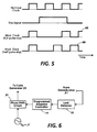
- the lock detector 32 determines that the transmitted and locally generated code sequences have drifted out of phase alignment, so the lock detect signal becomes false ("0"), thereby causing the slip control signal to transition to a high logic level state ("1").
- This positive-going transition in the slip control signal triggers the phase slip circuit 31, thereby causing it to retard the phase of the code sequence generated by the code generator 23 (i. e., the so-called locally generated code sequence).
- the phase slip circuit 31 may retard the phase of the locally generated code sequence by deleting either a full clock pulse, as at 65, or a half clock pulse, as at 66, from the clock pulse train that is supplied by the clock pulse generator 21 prior to applying the pulse train to the code generator 23.
- the pulse generator 21 may generate pulses at any integer multiple of the nominal clock frequency, so that the corrective adjustments may be made in smaller fractional parts of a clock cycle and in integer mutliples of such fractional parts.
- the output frequency of pulse generator 21 is twice the nominal clock frequency for the code generator 23, the corrective phase adjustments can be as fine as a quarter of a clock cycle.
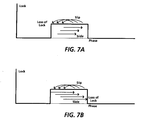
- a programmed adaptive controller 71 such as a programmed microprocessor or a custom or semicustom logic circuit, may be included for triggering the phase control circuit 31 (Fig. 1) at a predicted slip rate which is forecast to compensate for the inherent tendency of the locally generated code sequence to slide out of phase alignment with the transmitted code sequence. If the predicted slip rate is too high or two low, the transmitted and locally generated code sequences will tend to slip or slide out of phase alignment over time, as shown in Figs. 7A and 7B, respectively.
- a suitable lock detector 32 advantageously is included for restoring the lock whenever it is lost and for adaptively adjusting the predicted slip rate of the controller 71 to cause it to more accurately predict the frequency and/or magnitude of the incremental phase adjustments that are needed to maintain the locally generated code sequence in phase alignment with the transmitted code sequence.
- the synchronization methods and means that this invention provides are well suited for direct sequence spread-spectrum communication systems of the type in which the receivers utilize locally generated pseudo-random code sequences for despreading the received signal spectrum.
- the synchronization provided by this invention is compatible with the use of code-division multiplexing for sharing the available frequency spectrum among the parties to a plurality of different, potentially time overlapping communication sessions.
- such synchronization is achieved without requiring that the receivers derive or otherwise duplicate the frequency at which the transmitted code sequence is being clocked, thereby avoiding the design constraints of existing carrier lock tracking synchronization techniques.
- the "slip on actual and/or predicted loss of lock" synchronization which this invention contemplates is well suited for direct sequence spread-spectrum communications systems wherein the amount of power consumed by the receivers is of significant concern.
Landscapes
- Engineering & Computer Science (AREA)
- Computer Networks & Wireless Communication (AREA)
- Signal Processing (AREA)
- Synchronisation In Digital Transmission Systems (AREA)
- Cable Transmission Systems, Equalization Of Radio And Reduction Of Echo (AREA)
Applications Claiming Priority (2)
| Application Number | Priority Date | Filing Date | Title |
|---|---|---|---|
| US546456 | 1990-06-29 | ||
| US07/546,456 US5101417A (en) | 1990-06-29 | 1990-06-29 | Phase controlled synchronization for direct sequence spread-spectrum communication systems |
Publications (3)
| Publication Number | Publication Date |
|---|---|
| EP0465165A2 true EP0465165A2 (de) | 1992-01-08 |
| EP0465165A3 EP0465165A3 (en) | 1993-02-24 |
| EP0465165B1 EP0465165B1 (de) | 1997-05-28 |
Family
ID=24180497
Family Applications (1)
| Application Number | Title | Priority Date | Filing Date |
|---|---|---|---|
| EP91305890A Expired - Lifetime EP0465165B1 (de) | 1990-06-29 | 1991-06-28 | Phasengesteuerte Synchronisation für "Direkt-sequence"-Spreizspektrumübertragungssysteme |
Country Status (5)
| Country | Link |
|---|---|
| US (1) | US5101417A (de) |
| EP (1) | EP0465165B1 (de) |
| JP (1) | JPH0748710B2 (de) |
| CA (1) | CA2041913C (de) |
| DE (1) | DE69126246T2 (de) |
Cited By (3)
| Publication number | Priority date | Publication date | Assignee | Title |
|---|---|---|---|---|
| RU2116700C1 (ru) * | 1997-08-06 | 1998-07-27 | Научно-производственный кооператив "СИГМА" при Томской государственной академии систем управления и радиоэлектроники | Устройство связи |
| WO1998053436A1 (en) * | 1997-05-20 | 1998-11-26 | Smartmove, Naamloze Vennootschap | Method and device for establishing a wireless communication between vehicles and communication equipment erected along the road |
| EP0739101A3 (de) * | 1995-03-27 | 2002-03-06 | Sanyo Electric Co. Ltd | Spreizspektrumsignalempfangsgerät |
Families Citing this family (22)
| Publication number | Priority date | Publication date | Assignee | Title |
|---|---|---|---|---|
| CN1088035A (zh) * | 1992-04-15 | 1994-06-15 | 客运电迅传送有限公司 | 信号分配系统 |
| US5533046A (en) * | 1992-10-08 | 1996-07-02 | Lund; Vanmetre | Spread spectrum communication system |
| US5570349A (en) * | 1994-06-07 | 1996-10-29 | Stanford Telecommunications, Inc. | Wireless direct sequence spread spectrum digital cellular telephone system |
| US5590160A (en) * | 1992-12-30 | 1996-12-31 | Nokia Mobile Phones Ltd. | Symbol and frame synchronization in both a TDMA system and a CDMA |
| US5414699A (en) * | 1993-09-27 | 1995-05-09 | Motorola, Inc. | Method and apparatus for receiving and decoding communication signals in a CDMA receiver using partial de-correlation |
| US5459758A (en) | 1993-11-02 | 1995-10-17 | Interdigital Technology Corporation | Noise shaping technique for spread spectrum communications |
| US5832027A (en) * | 1993-11-19 | 1998-11-03 | Victor Company Of Japan, Ltd. | Spread spectrum modulating and demodulating apparatus for transmission and reception of FSK and PSK signals |
| KR100217715B1 (ko) * | 1993-12-31 | 1999-09-01 | 윤종용 | 직접확산/부호분할 다중접근 시스템에서의 업-링크 접근 시스템 |
| US5450458A (en) * | 1994-08-05 | 1995-09-12 | International Business Machines Corporation | Method and apparatus for phase-aligned multiple frequency synthesizer with synchronization window decoder |
| JP2655107B2 (ja) * | 1994-12-09 | 1997-09-17 | 日本電気株式会社 | スペクトラム拡散受信機 |
| US5691974A (en) * | 1995-01-04 | 1997-11-25 | Qualcomm Incorporated | Method and apparatus for using full spectrum transmitted power in a spread spectrum communication system for tracking individual recipient phase, time and energy |
| US5742595A (en) * | 1995-06-02 | 1998-04-21 | Dsc Communications Corporation | Processing CDMA signals |
| US6111911A (en) * | 1995-06-07 | 2000-08-29 | Sanconix, Inc | Direct sequence frequency ambiguity resolving receiver |
| US5615209A (en) * | 1995-07-26 | 1997-03-25 | Ericsson Inc. | Method and apparatus for CDMA signal orthogonalization |
| US5855339A (en) * | 1997-07-07 | 1999-01-05 | Raytheon Company | System and method for simultaneously guiding multiple missiles |
| US6700921B1 (en) * | 1999-01-07 | 2004-03-02 | Matsushita Electric Industrial Co., Ltd. | Spread-spectrum communication apparatus |
| US6614864B1 (en) | 1999-10-12 | 2003-09-02 | Itran Communications Ltd. | Apparatus for and method of adaptive synchronization in a spread spectrum communications receiver |
| US6961369B1 (en) | 1999-11-09 | 2005-11-01 | Aware, Inc. | System and method for scrambling the phase of the carriers in a multicarrier communications system |
| US7197410B2 (en) * | 2004-08-04 | 2007-03-27 | Seagate Technology Llc | Predicting loss of frequency lock between a motor control circuit and a motor |
| US20060062341A1 (en) * | 2004-09-20 | 2006-03-23 | Edmondson John H | Fast-lock clock-data recovery system |
| JP4548324B2 (ja) * | 2005-12-02 | 2010-09-22 | 沖電気工業株式会社 | 1対n通信システム、同期確立方法及び同期追従方法 |
| CN106230475B (zh) * | 2016-07-06 | 2018-10-02 | 北京理工大学 | 一种基于Tong检测器伪码多普勒补偿捕获方法及装置 |
Family Cites Families (5)
| Publication number | Priority date | Publication date | Assignee | Title |
|---|---|---|---|---|
| US4638494A (en) * | 1970-08-19 | 1987-01-20 | Sperry Corporation | System for the acquisition of code signals |
| DE3302828A1 (de) * | 1983-01-28 | 1984-08-02 | Standard Elektrik Lorenz Ag, 7000 Stuttgart | Empfangsgeraet |
| US4639932A (en) | 1985-08-29 | 1987-01-27 | Rca Corporation | Clock rate spread spectrum |
| JPS6333026A (ja) * | 1986-07-28 | 1988-02-12 | Hitachi Ltd | スペクトラム拡散受信機の同期確立方式 |
| DE69028838T2 (de) * | 1989-12-29 | 1997-03-06 | Xerox Corp | Kodeangepasste Synchronisation des Übertragungskodetaktes für Spreizspektrumübertragungssysteme |
-
1990
- 1990-06-29 US US07/546,456 patent/US5101417A/en not_active Expired - Lifetime
-
1991
- 1991-05-07 CA CA002041913A patent/CA2041913C/en not_active Expired - Lifetime
- 1991-06-21 JP JP3150641A patent/JPH0748710B2/ja not_active Expired - Fee Related
- 1991-06-28 EP EP91305890A patent/EP0465165B1/de not_active Expired - Lifetime
- 1991-06-28 DE DE69126246T patent/DE69126246T2/de not_active Expired - Lifetime
Cited By (4)
| Publication number | Priority date | Publication date | Assignee | Title |
|---|---|---|---|---|
| EP0739101A3 (de) * | 1995-03-27 | 2002-03-06 | Sanyo Electric Co. Ltd | Spreizspektrumsignalempfangsgerät |
| WO1998053436A1 (en) * | 1997-05-20 | 1998-11-26 | Smartmove, Naamloze Vennootschap | Method and device for establishing a wireless communication between vehicles and communication equipment erected along the road |
| BE1011160A3 (nl) * | 1997-05-20 | 1999-05-04 | Smartmove Naamloze Vennootscha | Werkwijze en inrichting voor het tot stand brengen van een draadloze communicatie tussen voertuigen en communicatieapparatuur opgesteld langs de weg. |
| RU2116700C1 (ru) * | 1997-08-06 | 1998-07-27 | Научно-производственный кооператив "СИГМА" при Томской государственной академии систем управления и радиоэлектроники | Устройство связи |
Also Published As
| Publication number | Publication date |
|---|---|
| US5101417A (en) | 1992-03-31 |
| DE69126246T2 (de) | 1997-11-13 |
| EP0465165A3 (en) | 1993-02-24 |
| CA2041913C (en) | 1995-08-01 |
| DE69126246D1 (de) | 1997-07-03 |
| EP0465165B1 (de) | 1997-05-28 |
| CA2041913A1 (en) | 1991-12-30 |
| JPH0748710B2 (ja) | 1995-05-24 |
| JPH04233839A (ja) | 1992-08-21 |
Similar Documents
| Publication | Publication Date | Title |
|---|---|---|
| US5101417A (en) | Phase controlled synchronization for direct sequence spread-spectrum communication systems | |
| US4122393A (en) | Spread spectrum detector | |
| CA1302539C (en) | Spread spectrum power line communications | |
| US5280499A (en) | Spread spectrum communication system | |
| US4532635A (en) | System and method employing two hop spread spectrum signal transmissions between small earth stations via a satellite and a large earth station and structure and method for synchronizing such transmissions | |
| EP0477862B1 (de) | Spreizbandkommunikationssystem | |
| US20070002934A1 (en) | Spread spectrum reception using a reference code signal | |
| JPH0292035A (ja) | 拡散スペクトル受信機における遅延ロックループ回路 | |
| EP0988726A1 (de) | Verfahren und schaltung zur synchronisierung in einem kommunikationssystem | |
| US5222075A (en) | Transmitted code clock code-matching synchronization for spread-spectrum communication systems | |
| US4559633A (en) | Spread spectrum system | |
| WO1993019547A1 (en) | Phase adjustment method and apparatus for use in a clock recovery circuit | |
| US4884284A (en) | Spread spectrum receiver | |
| WO1999057817A2 (en) | Code division multiple access transmitter and receiver | |
| US4457003A (en) | Time reference tracking loop for frequency hopping systems | |
| EP0435593B1 (de) | Kodeangepasste Synchronisation des Übertragungskodetaktes für Spreizspektrumübertragungssysteme | |
| GB2313750A (en) | Digital delay locked loop | |
| JP2770995B2 (ja) | スペクトラム拡散通信用受信装置 | |
| JP3183493B2 (ja) | スペクトル拡散受信装置 | |
| JPH02164150A (ja) | スペクトラム拡散通信装置 | |
| CA1295393C (en) | Spread spectrum power line communications | |
| KR200233224Y1 (ko) | 피엔코드발생제어장치 | |
| JPH0312497B2 (de) | ||
| JPH11186998A (ja) | 移動無線受信装置 | |
| JPH0234537B2 (de) |
Legal Events
| Date | Code | Title | Description |
|---|---|---|---|
| PUAI | Public reference made under article 153(3) epc to a published international application that has entered the european phase |
Free format text: ORIGINAL CODE: 0009012 |
|
| AK | Designated contracting states |
Kind code of ref document: A2 Designated state(s): DE FR GB |
|
| PUAL | Search report despatched |
Free format text: ORIGINAL CODE: 0009013 |
|
| AK | Designated contracting states |
Kind code of ref document: A3 Designated state(s): DE FR GB |
|
| 17P | Request for examination filed |
Effective date: 19930803 |
|
| 17Q | First examination report despatched |
Effective date: 19960419 |
|
| GRAG | Despatch of communication of intention to grant |
Free format text: ORIGINAL CODE: EPIDOS AGRA |
|
| GRAH | Despatch of communication of intention to grant a patent |
Free format text: ORIGINAL CODE: EPIDOS IGRA |
|
| GRAH | Despatch of communication of intention to grant a patent |
Free format text: ORIGINAL CODE: EPIDOS IGRA |
|
| GRAA | (expected) grant |
Free format text: ORIGINAL CODE: 0009210 |
|
| AK | Designated contracting states |
Kind code of ref document: B1 Designated state(s): DE FR GB |
|
| REF | Corresponds to: |
Ref document number: 69126246 Country of ref document: DE Date of ref document: 19970703 |
|
| ET | Fr: translation filed | ||
| PLBE | No opposition filed within time limit |
Free format text: ORIGINAL CODE: 0009261 |
|
| STAA | Information on the status of an ep patent application or granted ep patent |
Free format text: STATUS: NO OPPOSITION FILED WITHIN TIME LIMIT |
|
| 26N | No opposition filed | ||
| REG | Reference to a national code |
Ref country code: GB Ref legal event code: IF02 |
|
| PGFP | Annual fee paid to national office [announced via postgrant information from national office to epo] |
Ref country code: FR Payment date: 20100709 Year of fee payment: 20 |
|
| PGFP | Annual fee paid to national office [announced via postgrant information from national office to epo] |
Ref country code: GB Payment date: 20100623 Year of fee payment: 20 Ref country code: DE Payment date: 20100625 Year of fee payment: 20 |
|
| REG | Reference to a national code |
Ref country code: DE Ref legal event code: R071 Ref document number: 69126246 Country of ref document: DE |
|
| REG | Reference to a national code |
Ref country code: DE Ref legal event code: R071 Ref document number: 69126246 Country of ref document: DE |
|
| REG | Reference to a national code |
Ref country code: GB Ref legal event code: PE20 Expiry date: 20110627 |
|
| PG25 | Lapsed in a contracting state [announced via postgrant information from national office to epo] |
Ref country code: GB Free format text: LAPSE BECAUSE OF EXPIRATION OF PROTECTION Effective date: 20110627 |
|
| PG25 | Lapsed in a contracting state [announced via postgrant information from national office to epo] |
Ref country code: DE Free format text: LAPSE BECAUSE OF EXPIRATION OF PROTECTION Effective date: 20110629 |