EP0464896A2 - Procédé d'amélioration d'image et dispositif de mise en oeuvre de ce procédé - Google Patents
Procédé d'amélioration d'image et dispositif de mise en oeuvre de ce procédé Download PDFInfo
- Publication number
- EP0464896A2 EP0464896A2 EP91201556A EP91201556A EP0464896A2 EP 0464896 A2 EP0464896 A2 EP 0464896A2 EP 91201556 A EP91201556 A EP 91201556A EP 91201556 A EP91201556 A EP 91201556A EP 0464896 A2 EP0464896 A2 EP 0464896A2
- Authority
- EP
- European Patent Office
- Prior art keywords
- signal
- kernel
- value
- values
- image
- Prior art date
- Legal status (The legal status is an assumption and is not a legal conclusion. Google has not performed a legal analysis and makes no representation as to the accuracy of the status listed.)
- Granted
Links
Images

Classifications
-
- H—ELECTRICITY
- H03—ELECTRONIC CIRCUITRY
- H03H—IMPEDANCE NETWORKS, e.g. RESONANT CIRCUITS; RESONATORS
- H03H21/00—Adaptive networks
- H03H21/0012—Digital adaptive filters
Definitions
- the invention relates to a method for low-pass filtering and an arrangement for performing such a method.
- a signal value and a filtered signal value is derived from a fixed number of adjacent values which together form a kernel of signal values, for example by forming the arithmetic mean.
- a "kernel” is a part of the signal consisting of several successive signal values. To generate a sequence of such filtered values, the kernel is shifted relative to the signal by adding a signal value on one side of the kernel and eliminating a signal value on the other side. The size of the kernel determines the filtering effect. With a large kernel there is a strong signal smoothing, but signal jumps are smoothed out. A smaller kernel results in weaker smoothing, but better playback of signal jumps.
- This task is achieved according to the invention in that adaptive filtering is provided for the signal, in which the averaging interval is determined as a function of a slope of the signal.
- the method according to the invention can be used for filtering analog and digital audio or video signals in record players, in particular CD players, and in cassette recorders. It can be used for military tracking as well as for radar monitoring; In general, use is possible with noisy measurement and image signals, in the field of data transmission and measurement data acquisition, and in the processing of analog or time-discretely sampled signals.
- the signal to be filtered can be generated, for example, by digitizing an analog signal.
- One area of application of the invention is that a two-dimensional image is scanned line by line with at least one sensor and the image values are stored in a digital image memory and that the signal subjected to low-pass filtering is read out of the image memory in such a way that successive signal values are transmitted vertically by the image values image values adjacent to the line direction are formed.
- an image scanned line by line by at least one sensor there are generally no higher-frequency signal fluctuations in the line direction. At right angles to this, however, these can be caused by differences in sensitivity of the scanning sensor.
- These interference components can be effectively eliminated by the method according to the invention, while the actual image information is not influenced by the low-pass filtering if the filter parameters are selected appropriately.
- a preferred embodiment of the method in which the signal is formed by a sequence of digital signal values, in which a filtered signal value is derived from a kernel of signal values and a sequence of filtered signal values is obtained by shifting the kernel relative to the signal by one reference point in each case that at least one of the signal values adjacent to the kernel, which was not previously contained in the kernel, is compared with a value derived from the kernel and that the kernel size is increased to a maximum value in the case of small deviations in steps and reduced to a minimum value in the case of large deviations becomes.
- the signal is "analyzed” by determining the difference between a value derived from the kernel and a signal value which is "before” the kernel, i.e. which has not yet passed the kernel.
- the signal smoothing is amplified.
- the rear edge of the kernel remains in place (the signal value longest in the kernel remains part of the kernel), and the front end of the kernel is enlarged accordingly until a maximum value is reached.
- the kernel is then moved in the same way as in the known method.
- the signal value that is used to determine the deviation can be the signal value that - if the kernel size is constant - would be included in the kernel as the next or the next but one, or it could be formed from the weighted sum of these values.
- the value derived from the kernel can be formed by a (for example the last recorded) signal value or by a suitable combination of signal values contained therein.
- a preferred development of the invention provides that the difference between the arithmetic mean of the signal values belonging to the kernel and the two digits "in front" of the kernel is formed, that the kernel size is increased when the difference falls below a first threshold and that the kernel size is reduced if the difference does not fall below a second threshold that is at least as large as the first threshold.
- the kernel mean is at the same time the low pass filtered value.
- the first threshold should be such that the difference that occurs in the event of interference (e.g. noise) in the signal does not usually exceed it.
- the second threshold may be the same size as the first.
- An arrangement for carrying out the method according to the invention is characterized by a signal source for generating a digital signal, by a memory with a storage capacity corresponding to at least the maximum value of the kernel size and by a signal processor which executes the uses the signal values in the memory to generate a filtered signal value and is designed such that the kernel size is increased in steps up to a maximum value in the case of small changes within the signal and is reduced to a minimum value in the case of large changes in steps.
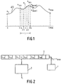
- the signal values x in ... x i + n form the kernel for the calculation of a low-pass filtered value y i at the support point i.
- y i is calculated at the support point i as the arithmetic mean of that for the kernel belonging signal values; however, it is also possible to calculate the filtered value y i from the appropriately weighted sum of the signal values contained in the kernel.
- a kernel is used to calculate the filtered value y i + 1 at the support point i + 1, which is shifted to the right by one support point compared to the previously described kernel.
- the value x in contained in the previous kernel is eliminated from the kernel sum and the value X i + n + 1 is included in the kernel sum.
- the length of the kernel remains constant; only its position in relation to the signal is shifted by one support point.
- the length of the kernel is made dependent on the signal curve in the invention.
- the difference between the two positions "in front" of the kernel signal value x i + n + 2 and the filtered value y i is formed at the support point i, which is, for example, the arithmetic mean of all values in the kernel.
- the kernel size is reduced, on the one hand by eliminating the newly added signal value (x i + n + 1 ) and the oldest signal value (X in-1 ).
- the front interpolation point (i + n) does not change its position when the kernel is moved, and this applies until the kernel size has reached a predetermined minimum value, at which the kernel only comprises one signal value, for example. The signal jump is then processed with this small kernel.
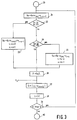
- a circuit arrangement for carrying out the method according to the invention is shown schematically in FIG. It has a digital signal source 1, which supplies a sequence of digital signal values.
- the signal values are continuously stored in a memory 2 which has at least two more memory locations than signal values contained in a kernel of maximum length. With each new signal value that is read into the memory 2, the already stored signal values are shifted by one memory location (to the left in FIG. 2), the longest value in the memory (in the present case this is the value x iN ) disappears.
- the signal processor could contain hardware tailored to the problem. However, the signal processor 3 is preferably designed to be programmable and comprises a microprocessor or a larger digital computer.
- Figure 3 shows part of a flow chart of the signal processing program executed by the signal processor.
- 30 denotes a program part which effects the initialization and the first filtered ones Returns values for the signal start.
- the program can correspond to the known methods with constant kernel length. It is assumed that a filtered signal value y i-1 has been calculated for a support point i-1 and that the variables Su, L, D and i have also been specified.
- the value Su represents the sum of the signal values (x in-1 .... x i + n-1 ), which correspond to the position of the kernel around the support point i-1, while L represents the value y i-1 filtered proper kernel length is.
- the sum is then first changed in a program step 31 by adding the value x i + n and subtracting the value x in-1 .
- the newly calculated total value Su therefore corresponds to the sum of the signal values of a kernel around the central value x i .
- the first threshold value S1 should be adapted to the noise or interference level, so that it can generally be exceeded by the difference D only when the useful signal changes, but not only by interference, noise or the like.
- the value N1 specifies the maximum size of the kernel (2N1 + 1) up to which the kernel can be enlarged. It should contain significantly fewer signal values than the signal to be filtered.
- the program only branches to block 33 if both conditions are met.
- the kernel sum (recalculated in 31) is increased by the two signal values on both sides of the - shifted - kernel.
- the sum Su formed in block 33 differs from the original sum Su in that the values labeled x i + n + 1 and x i + n have been added in FIG. 1.
- a branch is made to block 34, in which a further query takes place. It is checked whether the difference D is not less than a second threshold value S2 and whether the value n is greater than a minimum value No, for example greater than 0.
- the second threshold value S2 must be greater than or equal to the first threshold value S1. If the two threshold values are the same, the kernel size changes continuously as long as n remains between the maximum value N1 and the minimum value No; otherwise there is an area in which successive filter values can also have the same kernel length.
- the kernel sum is first recalculated therein by subtracting the first and last signal values from the sum Su newly calculated in block 31. This boils down to the fact that the kernel symbolized by dashed lines in FIG. 1 does not take into account the two outer signal values when forming the sum. This corresponds to the sum of a kernel, whose central support point is i + 1 and whose size is reduced by 2. Accordingly, in block 35 the value L is reduced by 2 and the value n by 1.
- the program proceeds to block 36, where the filtered value y i is calculated.
- the quotient Su / L is formed for this purpose (arithmetic mean), Su and L possibly being recalculated in one of the blocks 33 or 35 compared to the value specified by the block 31.
- the signal values filtered in this way can be output in a suitable manner; however, they can also be saved in a memory.
- the amount of the difference between the filtered value y i and the signal value (x i + n + 2 ) is then formed in a block 37D.
- the index i is increased by 1 and thus adapted to the new location of the kernel. This can be done, for example, by shifting all signal values in the memory to the next memory location.
- a block 39 it is finally checked whether the kernel has already reached the last support point imax. If this is the case, then an end of the program takes place in program part 40, possibly with the output of appropriately generated boundary values.
- block 39 If, on the other hand, the condition of block 39 is fulfilled, then a return is made to block 31, whereby a program loop is formed which is run through until the kernel reaches the end region of the signal. If the program loop is run through several times, it can happen that block 33 is called each time and the kernel size is accordingly increased by 2 each time until the maximum value N1 is reached. In this case, the first and the last signal value in the memory 2 are also used for processing. - Likewise can in the case of strong signal fluctuations, block 35 must also be run through repeatedly until the minimum length No is reached.
- FIG. 5 shows the kernel size L used to smooth the signal x (t) in FIG. 4 as a function of the support point i in the same area as there. It can be seen that the maximum kernel length in the signal section shown is not reached at any point, while the minimum kernel size reaches the value 1 at several points each characterized by steep signal edges that extend over a larger area.
- One area of application of the method according to the invention is the filtering of signals which arise in the case of X-ray recordings which are generated by means of a photoconductor, as described in the earlier German patent application P 40 06 181.7.
- the surface of a photoconductor that is more or less discharged by an x-ray is scanned in a row by means of one or more sensors that detect the surface charge, then digitized and stored.
- the sensors and the downstream one Electronics are exposed to drift influences and the like, which in the subsequently reconstructed image lead to strip-shaped artifacts running parallel to the line direction. These artifacts can be eliminated by low-pass filtering perpendicular to the line direction.
- the signal source 1 (FIG.
- the kernel sum Su may be twice calculated, namely once in block 31 and possibly a second time in one of blocks 33 or 35. This double calculation can be avoided if the sum calculation Su for the moved kernel is not carried out in block 31, but in one behind block 34 block to insert.
- the kernel sum in block 33 would have to be increased by the next two x i + n + 1 and x i + n + 2 signal values, while in block 35 it would have to be reduced by the two kernel values x i + n and x in-1 ought to.
- the arithmetic mean of the signals of the undisplaced kernel would be compared in block 31 with the signal value after the next (x i + n + 2 ).
Landscapes
- Complex Calculations (AREA)
- Image Processing (AREA)
- Filters That Use Time-Delay Elements (AREA)
Applications Claiming Priority (2)
| Application Number | Priority Date | Filing Date | Title |
|---|---|---|---|
| DE4020643A DE4020643A1 (de) | 1990-06-29 | 1990-06-29 | Verfahren zur tiefpassfilterung und anordnung zur durchfuehrung des verfahrens |
| DE4020643 | 1990-06-29 |
Publications (3)
| Publication Number | Publication Date |
|---|---|
| EP0464896A2 true EP0464896A2 (fr) | 1992-01-08 |
| EP0464896A3 EP0464896A3 (en) | 1992-08-05 |
| EP0464896B1 EP0464896B1 (fr) | 1996-02-28 |
Family
ID=6409277
Family Applications (1)
| Application Number | Title | Priority Date | Filing Date |
|---|---|---|---|
| EP91201556A Expired - Lifetime EP0464896B1 (fr) | 1990-06-29 | 1991-06-19 | Procédé d'amélioration d'image et dispositif de mise en oeuvre de ce procédé |
Country Status (4)
| Country | Link |
|---|---|
| US (1) | US5237524A (fr) |
| EP (1) | EP0464896B1 (fr) |
| JP (1) | JPH04233817A (fr) |
| DE (2) | DE4020643A1 (fr) |
Families Citing this family (10)
| Publication number | Priority date | Publication date | Assignee | Title |
|---|---|---|---|---|
| US5424783A (en) * | 1993-02-10 | 1995-06-13 | Wong; Yiu-Fai | Clustering filter method for noise filtering, scale-space filtering and image processing |
| US5764552A (en) * | 1993-02-18 | 1998-06-09 | The Dow Chemical Company | Method for adjusting an adaptive exponential filter |
| ATE167765T1 (de) * | 1993-02-18 | 1998-07-15 | Dow Deutschland Inc | Methode zur einstellung eines adaptiven exponentialfilters und adaptives exponentialfilter |
| AUPP779798A0 (en) * | 1998-12-18 | 1999-01-21 | Canon Kabushiki Kaisha | A modified kernel for image interpolation |
| US6449330B1 (en) * | 2001-06-28 | 2002-09-10 | Ge Medical Systems Global Technology Company, Llc | Methods and apparatus for artifact reduction in computed tomographic imaging |
| DE10327578A1 (de) * | 2003-06-18 | 2005-01-13 | Micronas Gmbh | Verfahren und Vorrichtung zur Filterung eines Signals |
| US20050201605A1 (en) * | 2004-03-11 | 2005-09-15 | Jianying Li | Methods and apparatus for CT smoothing to reduce artifacts |
| KR100643305B1 (ko) * | 2005-02-14 | 2006-11-10 | 삼성전자주식회사 | 컨볼루션 커널을 이용한 라인 패턴 처리 방법 및 장치 |
| JP5538684B2 (ja) * | 2008-03-13 | 2014-07-02 | キヤノン株式会社 | 画像処理装置、画像処理方法、プログラム、及び記憶媒体 |
| FR2956496B1 (fr) * | 2010-02-17 | 2012-03-09 | Commissariat Energie Atomique | Procede de mesure en ligne de rayonnements ionisants |
Citations (1)
| Publication number | Priority date | Publication date | Assignee | Title |
|---|---|---|---|---|
| DE3538735A1 (de) * | 1985-10-31 | 1987-05-07 | Bosch Gmbh Robert | Verfahren und schaltungsanordnung zum verdecken von fehlern in einem digitalen videosignal |
Family Cites Families (3)
| Publication number | Priority date | Publication date | Assignee | Title |
|---|---|---|---|---|
| FR2451680A1 (fr) * | 1979-03-12 | 1980-10-10 | Soumagne Joel | Discriminateur parole/silence pour interpolation de la parole |
| US4868773A (en) * | 1985-03-15 | 1989-09-19 | Purdue Research Foundation | Digital filtering by threshold decomposition |
| US4894794A (en) * | 1985-10-15 | 1990-01-16 | Polaroid Corporation | System for providing continous linear interpolation |
-
1990
- 1990-06-29 DE DE4020643A patent/DE4020643A1/de not_active Withdrawn
-
1991
- 1991-06-07 US US07/712,219 patent/US5237524A/en not_active Expired - Fee Related
- 1991-06-19 EP EP91201556A patent/EP0464896B1/fr not_active Expired - Lifetime
- 1991-06-19 DE DE59107447T patent/DE59107447D1/de not_active Expired - Fee Related
- 1991-06-26 JP JP3180597A patent/JPH04233817A/ja active Pending
Patent Citations (1)
| Publication number | Priority date | Publication date | Assignee | Title |
|---|---|---|---|---|
| DE3538735A1 (de) * | 1985-10-31 | 1987-05-07 | Bosch Gmbh Robert | Verfahren und schaltungsanordnung zum verdecken von fehlern in einem digitalen videosignal |
Non-Patent Citations (2)
| Title |
|---|
| IEEE PACIFIC RIM CONF. ON COMMUNICATIONS, COMP., AND SIGNAL PROCESSING. VICTORIA (CA);JUNE 4-5 1987: J.U. QUISTGAARD et al "AN ADAPTIVE WINDOW MEDIAN FILTER" P. 440-443. * |
| IEEE TRANSACTIONS ON ACOUSTICS,SPEECH AND SIGNAL PROCESSING. vol. 32, no. 3, June 1984, NEW YORK US pages 571 - 576; C.A. POMALA-RAEZ ET AL: 'AN ADAPTIVE NONLINEAR EDGE-PRESERVING FILTER' * |
Also Published As
| Publication number | Publication date |
|---|---|
| US5237524A (en) | 1993-08-17 |
| EP0464896B1 (fr) | 1996-02-28 |
| JPH04233817A (ja) | 1992-08-21 |
| EP0464896A3 (en) | 1992-08-05 |
| DE59107447D1 (de) | 1996-04-04 |
| DE4020643A1 (de) | 1992-01-02 |
Similar Documents
| Publication | Publication Date | Title |
|---|---|---|
| DE2716739C3 (de) | Verfahren zur Detektion von Signalen | |
| EP1301993B1 (fr) | Procede et dispositif de compression et/ou decompression de donnees et d'analyse et de representation de donnees | |
| DE4411179A1 (de) | Bildeinfangvorrichtung | |
| DE69627755T2 (de) | Verfahren und Vorrichtung zur temporären Rauschfilterung einer Bildfolge | |
| WO2000077675A1 (fr) | Reduction des interferences dans des signaux de mesure a signal utile periodique | |
| DE69627756T2 (de) | Verfahren und Vorrichtung zur temporären Rauschfilterung einer Bildfolge | |
| DE3837066A1 (de) | Rauschunterdrueckungseinrichtung | |
| DE3144659A1 (de) | Einrichtung zur auswertung von ekg-signalen | |
| DE69824230T2 (de) | Verarbeitungssystem einer verrauschten Bildsequenz und medizinisches Untersuchungsgerät mit einem solchen System | |
| EP0212528A2 (fr) | Procédé de détermination du point de départ et du point final d'un signal tridimensionnel représenté par une courbe fermée | |
| EP0464896A2 (fr) | Procédé d'amélioration d'image et dispositif de mise en oeuvre de ce procédé | |
| DE3707417A1 (de) | Verfahren zur wiederherstellung der hintergrunderscheinung zweidimensional gefilterter seismischer daten | |
| EP0685706A1 (fr) | Procédé pour la détermination de la partie offset d'un signal de mesure en temps réel | |
| EP0607393A1 (fr) | Architecture neuronale de filtrage non-lineaire adaptatif d'interferences perturbatrices | |
| DE19860036C1 (de) | Verfahren zum Reduzieren von spalten- oder zeilenkorreliertem bzw. teilspalten- oder teilzeilenkorreliertem Rauschen bei einem digitalen Bildsensor sowie Vorrichtung zur Aufnahme von Strahlungsbildern | |
| DE102005011125A1 (de) | Verfahren und Vorrichtung zur inkrementellen Berechnung des General Linear Model bei zeitweiser Korrelation der Modellfunktionen | |
| DE10008792A1 (de) | Vorrichtung zur Verarbeitung von Körpersignalen | |
| DE19636865C1 (de) | Erkennung von schräglaufenden Kratzern in Videosignalen | |
| DE112021005763T5 (de) | Vermeidung eines sättigungsbedingten Phasensprungs bei DAS | |
| DE19825070C1 (de) | Verfahren zur Bestimmung eines eine Variation zwischen einer meßbaren Größe und einer meßbaren Referenzgröße repräsentierenden Wertes | |
| EP0444737B1 (fr) | Dispositif pour la lecture par balayage d'une radiographie | |
| DE2717530B2 (de) | Verfahren zur Störbefreiung von Signalen | |
| DE69937333T2 (de) | Datenverarbeitungsgeräte und Datenverarbeitungsverfahren | |
| EP1586914A2 (fr) | Filtres digitaux pour application en RMN ou IRM | |
| DE3710006C2 (fr) |
Legal Events
| Date | Code | Title | Description |
|---|---|---|---|
| PUAI | Public reference made under article 153(3) epc to a published international application that has entered the european phase |
Free format text: ORIGINAL CODE: 0009012 |
|
| AK | Designated contracting states |
Kind code of ref document: A2 Designated state(s): DE FR GB |
|
| PUAL | Search report despatched |
Free format text: ORIGINAL CODE: 0009013 |
|
| AK | Designated contracting states |
Kind code of ref document: A3 Designated state(s): DE FR GB |
|
| 17P | Request for examination filed |
Effective date: 19930203 |
|
| 17Q | First examination report despatched |
Effective date: 19950524 |
|
| GRAA | (expected) grant |
Free format text: ORIGINAL CODE: 0009210 |
|
| AK | Designated contracting states |
Kind code of ref document: B1 Designated state(s): DE FR GB |
|
| REF | Corresponds to: |
Ref document number: 59107447 Country of ref document: DE Date of ref document: 19960404 |
|
| ET | Fr: translation filed | ||
| GBT | Gb: translation of ep patent filed (gb section 77(6)(a)/1977) |
Effective date: 19960426 |
|
| PGFP | Annual fee paid to national office [announced via postgrant information from national office to epo] |
Ref country code: GB Payment date: 19960603 Year of fee payment: 6 |
|
| PGFP | Annual fee paid to national office [announced via postgrant information from national office to epo] |
Ref country code: FR Payment date: 19960626 Year of fee payment: 6 |
|
| PGFP | Annual fee paid to national office [announced via postgrant information from national office to epo] |
Ref country code: DE Payment date: 19960823 Year of fee payment: 6 |
|
| PLBE | No opposition filed within time limit |
Free format text: ORIGINAL CODE: 0009261 |
|
| STAA | Information on the status of an ep patent application or granted ep patent |
Free format text: STATUS: NO OPPOSITION FILED WITHIN TIME LIMIT |
|
| 26N | No opposition filed | ||
| PG25 | Lapsed in a contracting state [announced via postgrant information from national office to epo] |
Ref country code: GB Free format text: LAPSE BECAUSE OF NON-PAYMENT OF DUE FEES Effective date: 19970619 |
|
| GBPC | Gb: european patent ceased through non-payment of renewal fee |
Effective date: 19970619 |
|
| PG25 | Lapsed in a contracting state [announced via postgrant information from national office to epo] |
Ref country code: FR Free format text: LAPSE BECAUSE OF NON-PAYMENT OF DUE FEES Effective date: 19980227 |
|
| PG25 | Lapsed in a contracting state [announced via postgrant information from national office to epo] |
Ref country code: DE Free format text: LAPSE BECAUSE OF NON-PAYMENT OF DUE FEES Effective date: 19980303 |
|
| REG | Reference to a national code |
Ref country code: FR Ref legal event code: ST |
|
| REG | Reference to a national code |
Ref country code: FR Ref legal event code: ST |