EP0464436A2 - Brûleur cyclonique avec chambre de combustion cylindrique - Google Patents
Brûleur cyclonique avec chambre de combustion cylindrique Download PDFInfo
- Publication number
- EP0464436A2 EP0464436A2 EP91109846A EP91109846A EP0464436A2 EP 0464436 A2 EP0464436 A2 EP 0464436A2 EP 91109846 A EP91109846 A EP 91109846A EP 91109846 A EP91109846 A EP 91109846A EP 0464436 A2 EP0464436 A2 EP 0464436A2
- Authority
- EP
- European Patent Office
- Prior art keywords
- combustion chamber
- gas
- cyclone burner
- burner according
- outlet slot
- Prior art date
- Legal status (The legal status is an assumption and is not a legal conclusion. Google has not performed a legal analysis and makes no representation as to the accuracy of the status listed.)
- Granted
Links
Images

Classifications
-
- F—MECHANICAL ENGINEERING; LIGHTING; HEATING; WEAPONS; BLASTING
- F23—COMBUSTION APPARATUS; COMBUSTION PROCESSES
- F23C—METHODS OR APPARATUS FOR COMBUSTION USING FLUID FUEL OR SOLID FUEL SUSPENDED IN A CARRIER GAS OR AIR
- F23C3/00—Combustion apparatus characterised by the shape of the combustion chamber
- F23C3/006—Combustion apparatus characterised by the shape of the combustion chamber the chamber being arranged for cyclonic combustion
Definitions
- the invention relates to a cyclone burner with a cylindrical combustion chamber, as indicated in the preamble of claim 1.
- Outlet openings in the combustion chamber wall are known for the exit of solid particles from a cylindrical combustion chamber, US Pat. No. 3,357,383. Some of the solid particles located directly on the combustion chamber wall can be removed from the combustion chamber via these outlet openings. Inserts corresponding to a combustion grate for removing ash from a cyclone burner are described in DE-PS 10 24 663, a cyclone burner with a vertically arranged axis and removal of the solid particles from the funnel-shaped base is known from DE-PS 974 562.
- the object of the invention is in a cyclone burner to provide a rapid and as complete as possible separation possibility for the solid particles located in the area of the combustion chamber near the wall.
- At least one outlet slit on the inside of the cylindrical shell of the combustion chamber which has a wall step for introducing the solid particles, is used to remove the solid particles.
- the solid particles that collect on the inside of the casing in the combustion chamber are led via the wall step to the outlet slot and into a separation space into which the outlet slot opens.
- the wall step for the entry of the solid particles is open on its end face.
- the opening width of the outlet slot formed in this way results from the wall step height (height of the open end wall) measured in the radial direction, which then also determines the particle fraction that can be removed from the combustion chamber.
- the wall step is adjustable, claim 3.
- a complete separation of the solid particles separating out in the combustion chamber is supported according to claim 4 in that the outlet slot in the cylindrical jacket extends over its entire length. So that the solid particles from the combustion chamber can enter the separation space unhindered, the outlet slot has an outwardly wedge-shaped flow cross section, claim 5 in the separation space a negative pressure is generated compared to the pressure in the combustion chamber.
- a bypass line leading from the separating space to the exhaust line is preferably used for this purpose. The vacuum is set by an adjustable throttle valve in the bypass line, claim 8.
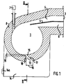
- Figures 1 to 3 show cyclone burners with cylindrical combustion chambers 1, the combustion chamber axes 2 are arranged horizontally.
- a gas supply 3 for a fuel gas / air mixture In the exemplary embodiment, the gas supply 3 has two flow spaces 5, 6 separated from one another by a partition 4, through which fuel gas in the flow space 5 and air in the flow space 6 are introduced into the combustion chamber 1.
- the fuel gas / air mixture that forms in the upper region of the combustion chamber is ignited at the start of the cyclone burner via a pilot burner 7.
- the pilot burner 7 is inserted into the combustion chamber 1 through its jacket 8. With the pilot burner 7, the combustion chamber 1 can also be preheated to a suitable ignition temperature before the entry of fuel gas and air, at which the fuel gas / air mixture is combustible from the time of ignition with formation of only small amounts of harmful gas.
- the exhaust gas formed in the combustion chamber 1 flows out via an exhaust gas line 9 with line parts 9a, 9b.
- the exhaust pipe 9 is connected to the front of the combustion chamber 1, in the exemplary embodiment on a front 10 centrally and parallel to the combustion chamber axis 2.
- the part 9a of the exhaust gas line 9, which forms the connection of the exhaust gas line to an end face 10 of the combustion chamber 1, has a narrower flow cross section 11 than the part 9b of the exhaust gas line 9 with the flow cross section 12.
- the part 9a can be nozzle-shaped, whereby the Flow cross-section 11 starting from the connection of the exhaust line from the end face 10 to the mouth of part 9a in part 9b expanded like a Laval nozzle. This accelerates and stabilizes the exhaust gas flow from the combustion chamber 1, with a mixing effect for the burnout at the same time of the exhaust gas is reached.
- the exhaust gas flows through part 9b to a heat exchanger not shown in the drawing.
- the outlet slot 13 In the lower region of the combustion chamber 1 there is an outlet slot 13 for the discharge of solid particles which are introduced into the combustion chamber 1 with the fuel gas. The solid particles fall via the outlet slot into a separating space 14 into which the outlet slot opens.
- the separating space has a closable opening 14a for ash removal from the separating space.
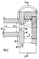
- the outlet slot 13 extends over the entire width B of the combustion chamber 1, see FIG. 2, and is formed by a wall step 15, the end face of which is open to the entry of solid particles.
- the outlet slot 13 has a flow cross section 16 which widens outwards in the jacket 8, the outlet slot widens outwards in a wedge shape.
- the wall step 15 is formed by a boundary surface 17, which is arranged at an angle to an opposite, radially extending boundary surface 18 of the outlet slot 13.
- the formation of the wall step 15, in particular the wall step height 19 with which the wall step projects into the combustion chamber 1, and the wedge-shaped widening of the outlet slot determine the solid particle fraction which is discharged into the separation chamber 14 via the outlet slot 13.
- the wall step height 19 of the wall step is adjustable.
- a wall step 15a is designed as a flap and movable about an axis 20. It can be rotated on the combustion chamber wall in accordance with the desired particle separation. Since the solid particles concentrate on the inside of the shell due to the centrifugal forces acting on them, the wall step 15a can be guided into the free combustion chamber space the thicker the gas layer carrying the particles is. However, the position of the wall step 15a also influences the optimal combustion process in the combustion chamber, it must be regulated accordingly.
- the outlet slot 13 runs in the jacket 8 at an angle 21 to the radial plane 22 of the combustion chamber 1. The angle 21 is dimensioned such that the particles emerge from the combustion chamber with as little resistance as possible.
- the outlet slot 13 has a uniform flow cross section 16a.
- a combustible gas mixture already enters the combustion chamber 1 via the gas supply 3.
- a control flap 24 is arranged in the mouth area 23 of the gas supply 3.
- the position of the control flap 24 is changed with the aim of changing the gas inlet cross section, with the aim of making it constant
- the entry velocity also influences the burnout of the gas mixture in the combustion chamber.
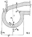
- combustion chamber 1 according to FIG. 3 is constructed in the same way as the combustion chamber according to the embodiment according to FIGS. 1 and 2.
- the same reference numerals as in FIGS. 1 and 2 were therefore used in FIG. 3.
- a bypass 25 leads from the separating space 14 to the exhaust gas line 9. It opens into part 9b of the exhaust gas line.
- a throttle valve 26 is used, the position of which allows the desired negative pressure in the separating chamber 14 to be set in relation to the pressure in the combustion chamber 1. The resulting pressure difference between combustion chamber 1 and separation chamber 14 influences the desired separation of the solid particles.
- baffle plates 27 are used in the exemplary embodiment according to FIG. 1 in the separating space 14 of the cyclone burner, which hold back the solid particles in the separating space.
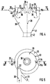
- FIGS. 4 and 5 show a cyclone burner whose combustion chamber axis 28 is arranged vertically.
- fuel gas and air are tangentially from the side into a combustion chamber 29 introduced via a fuel gas inlet 30 and an air line 31.
- solid particles enter the combustion chamber 29 into the combustion chamber, which are discharged from the combustion chamber 29 preferably via an outlet slot 34 which is offset approximately 225 ° from the access 32 in the jacket 33 of the combustion chamber.
- an adjustable wall step 15b is attached to the outlet slot 34.
- the solid particles emerge via the wall step 15b in a separating space 35 which is cylindrically shaped in the same way as the combustion chamber 29 and also has an axis arranged vertically.
- the axis of the separating space 35 coincides with the combustion chamber axis 28 in the exemplary embodiment, the combustion chamber 29 is thus arranged centrally in the separating space 35.
- the combustion chamber 29 has a chamber floor 36 that slopes conically from its center toward the jacket 33.
- passage openings for the solid particles are also provided in the bottom. The passage openings are not shown in FIG. 5.
- the exhaust gas flows out of the combustion chamber 29 centrally.
- Flow arrows 37 are shown schematically in FIG. 5 for the exhaust gas flow.
- the hot exhaust gas is removed within an exhaust gas line 38; in the exemplary embodiment, the exhaust gas line is connected to a heat exchanger (not shown in FIG. 5), via which the hot exhaust gas gives off its heat to a heating medium.
- the exhaust line 38 is open to the separating space 35.
- the gas penetrating into the separating space 35 when the solid particles are removed from the combustion chamber 29 can thus also be drawn off together with the exhaust gas directly via the exhaust line 38.
- a flue gas recirculation 39 is also connected to the separating chamber 35, the access of which can be opened by means of a regulating flap 40. The amount of gas returned through the flue gas recirculation is regulated by adjusting the opening width of the control flap 40 accordingly.
- a solid lock 42 is provided for emptying the separating space, which is opened for discharge depending on the amount of solid.
- the central position of the combustion chamber 29 within the separating space 35 and the free flow deflection of the exhaust gas in the ceiling area of the separating space serve to largely clean the hot exhaust gas withdrawing from the combustion chamber before entering the heat exchanger. Solid particles introduced into the combustion chamber by the fuel gas / air mixture are separated in the separation room according to the desired requirements. A clogging of the heat exchanger with dust is thus sufficiently prevented in the cyclone burner according to the invention.
- FIG. 6 A further combustion chamber with a horizontal combustion chamber axis is shown in cross section in FIG.
- This combustion chamber differs from the combustion chamber shown in FIGS. 1 and 2 essentially by a second particle outlet slot: in addition to a lower particle outlet slot 43 with wall step 44, which projects into the combustion chamber toward the interior 45, there is another particle outlet slot in the inlet area of the fuel gas and combustion air 46 arranged with wall step 47.
- the wall step 47 has a height 19 which lifts off from the wall side 48 of the interior 45.
- the particles entering the combustion chamber with the combustion gases are thus discharged from the combustion chamber at two points, the coarse particle fraction being discharged essentially via the particle outlet slot 46 and the finer fraction via the particle outlet slot 43.
- the heights 19 of the wall steps 44 and 47 can also be dimensioned and designed differently in accordance with the desired degree of separation in the combustion chamber.
- combustion air and fuel gas enter the combustion chamber separately at the gas supply 3, the combustion air via an air duct 49 opening at the gas supply 3, and the fuel gas via a fuel gas inlet duct 50.
- the combustion chamber according to FIG. 6 functions in the same way as the combustion chamber shown in FIGS. 1 and 2. Identically designed and functionally retained device parts are therefore marked in FIG. 6 with the same reference numerals as in the aforementioned figures.
Landscapes
- Engineering & Computer Science (AREA)
- Chemical & Material Sciences (AREA)
- Combustion & Propulsion (AREA)
- Mechanical Engineering (AREA)
- General Engineering & Computer Science (AREA)
- Cyclones (AREA)
- Incineration Of Waste (AREA)
- Combustion Of Fluid Fuel (AREA)
- Gasification And Melting Of Waste (AREA)
- Sampling And Sample Adjustment (AREA)
Applications Claiming Priority (2)
| Application Number | Priority Date | Filing Date | Title |
|---|---|---|---|
| DE4021005A DE4021005C1 (fr) | 1990-07-02 | 1990-07-02 | |
| DE4021005 | 1990-07-02 |
Publications (3)
| Publication Number | Publication Date |
|---|---|
| EP0464436A2 true EP0464436A2 (fr) | 1992-01-08 |
| EP0464436A3 EP0464436A3 (en) | 1992-03-25 |
| EP0464436B1 EP0464436B1 (fr) | 1995-08-09 |
Family
ID=6409487
Family Applications (1)
| Application Number | Title | Priority Date | Filing Date |
|---|---|---|---|
| EP91109846A Expired - Lifetime EP0464436B1 (fr) | 1990-07-02 | 1991-06-15 | Brûleur cyclonique avec chambre de combustion cylindrique |
Country Status (6)
| Country | Link |
|---|---|
| EP (1) | EP0464436B1 (fr) |
| AT (1) | ATE126341T1 (fr) |
| BR (1) | BR9102645A (fr) |
| DE (1) | DE4021005C1 (fr) |
| DK (1) | DK0464436T3 (fr) |
| HU (1) | HU211408B (fr) |
Cited By (1)
| Publication number | Priority date | Publication date | Assignee | Title |
|---|---|---|---|---|
| CN107270288A (zh) * | 2017-08-07 | 2017-10-20 | 段秀春 | 共模同步型工业烟气复燃循环处理模块、装置及方法 |
Families Citing this family (4)
| Publication number | Priority date | Publication date | Assignee | Title |
|---|---|---|---|---|
| DE102010002737B4 (de) | 2009-03-10 | 2024-07-18 | Erk Eckrohrkessel Holding Gmbh | Vorrichtung zur Durchführung eines Verfahrens zur Erzeugung von Dampf |
| DE102011111521A1 (de) | 2011-08-31 | 2013-02-28 | Robert Bosch Gmbh | Trichterförmige Sekundärbrennkammer |
| DE102011116723A1 (de) | 2011-10-24 | 2013-04-25 | Robert Bosch Gmbh | Sekundärbrennkammer mit Sekundärlufteindüsung |
| CN110440289B (zh) * | 2019-07-26 | 2021-01-08 | 中国航发沈阳发动机研究所 | 一种燃气轮机燃烧室燃料空气高效混合装置 |
Family Cites Families (8)
| Publication number | Priority date | Publication date | Assignee | Title |
|---|---|---|---|---|
| DE974562C (de) * | 1941-04-17 | 1961-02-09 | Aeg | Feuerung fuer fluessige, gasfoermige oder staubfoermige Brennstoffe |
| FR1076716A (fr) * | 1952-05-06 | 1954-10-28 | Babcock & Wilcox France | Perfectionnements aux foyers cyclones |
| DE1024663B (de) * | 1954-09-08 | 1958-02-20 | Heriberto Enrique Guillermo Ju | Zyklonbrenner |
| GB804570A (en) * | 1956-02-20 | 1958-11-19 | Babcock & Wilcox Ltd | Improvements in cyclone furnaces |
| US3179074A (en) * | 1962-02-21 | 1965-04-20 | Babcock & Wilcox Co | Cyclone furnace |
| US3357383A (en) * | 1965-08-05 | 1967-12-12 | Golovanov Nikolai Vasilievich | Horizontal cylindrical furnace with removal of liquid slag |
| DE3507371A1 (de) * | 1985-03-02 | 1986-09-04 | Norddeutsche Affinerie AG, 2000 Hamburg | Vorrichtung fuer die pyrometallurgische behandlung feinkoerniger, schmelzfluessige produkte ergebender feststoffe |
| DE3643040C1 (de) * | 1986-12-17 | 1988-02-25 | Gewerk Sophia Jakoba | Vorrichtung zum Verbrennen von Kohlenstaub |
-
1990
- 1990-07-02 DE DE4021005A patent/DE4021005C1/de not_active Expired - Lifetime
- 1990-11-12 HU HU907092A patent/HU211408B/hu unknown
-
1991
- 1991-06-15 EP EP91109846A patent/EP0464436B1/fr not_active Expired - Lifetime
- 1991-06-15 AT AT91109846T patent/ATE126341T1/de not_active IP Right Cessation
- 1991-06-15 DK DK91109846.5T patent/DK0464436T3/da active
- 1991-06-24 BR BR919102645A patent/BR9102645A/pt not_active IP Right Cessation
Cited By (2)
| Publication number | Priority date | Publication date | Assignee | Title |
|---|---|---|---|---|
| CN107270288A (zh) * | 2017-08-07 | 2017-10-20 | 段秀春 | 共模同步型工业烟气复燃循环处理模块、装置及方法 |
| CN107270288B (zh) * | 2017-08-07 | 2023-03-14 | 段秀春 | 共模同步型工业烟气复燃循环处理模块、装置及方法 |
Also Published As
| Publication number | Publication date |
|---|---|
| EP0464436B1 (fr) | 1995-08-09 |
| HU211408B (en) | 1995-11-28 |
| DK0464436T3 (da) | 1995-11-27 |
| HU907092D0 (en) | 1991-05-28 |
| ATE126341T1 (de) | 1995-08-15 |
| EP0464436A3 (en) | 1992-03-25 |
| BR9102645A (pt) | 1992-01-21 |
| HUT59473A (en) | 1992-05-28 |
| DE4021005C1 (fr) | 1991-08-14 |
Similar Documents
| Publication | Publication Date | Title |
|---|---|---|
| DE69525237T2 (de) | Wirbelschicht-Feuerungsanlage | |
| DE3306483C2 (fr) | ||
| EP0204912A2 (fr) | Procédé et dispositif à combustion de combustibles liquides et/ou solides pulvérulents | |
| EP0114062A2 (fr) | Procédé et dispositif pour la combustion de combustibles solides, en particulier du charbon, de la tourbe etc. | |
| EP0204176A2 (fr) | Chambre de combustion pour un appareil à combustion à lit fluidisé | |
| DE3907457A1 (de) | Verfahren und vorrichtung zur abscheidung fluessiger asche | |
| DE68918993T2 (de) | Zyklonofen. | |
| EP1658891A1 (fr) | Réacteur à lit fluidisé avec un séparateur cyclonique | |
| EP0464436B1 (fr) | Brûleur cyclonique avec chambre de combustion cylindrique | |
| DE69008599T2 (de) | Verbrennungsapparat. | |
| DE2745756C3 (de) | Verbrennungsofen | |
| DE3720963C2 (fr) | ||
| DE3708799C2 (fr) | ||
| DE3346536C2 (de) | Vorbrenner für Zementrohmehl | |
| DE3339317A1 (de) | Vorrichtung zur abscheidung von festen komponenten aus rauchgasen | |
| DE4435640A1 (de) | Verfahren und Brenner zur Verbrennung von staubförmigem Brennstoff | |
| AT397551B (de) | Verbrennungsofen | |
| DE60018148T2 (de) | Brenner mit gestufter Luft- und Brennstoffzufuhr | |
| EP0226140A2 (fr) | Procédé et dispositif de combustion de combustibles solides dans un lit fluidisé circulant | |
| DE68902948T2 (de) | Kessel. | |
| DE3309905C2 (de) | Verfahren und Vorrichtung zum Verbrennen fester Brennstoffe in pulverisierter Form | |
| EP3228935B1 (fr) | Procédé de combustion pauvre en oxyde d'azote de combustibles gazeux, solides ou liquides, en particulier de poussière de charbon, brûleur et installation de combustion destinée a exécuter le procédé | |
| DE3723478A1 (de) | Vorrichtung fuer die abscheidung von russ aus dem abgas eines verbrennungsmotors | |
| EP0097153B1 (fr) | Foyer de chaudiere | |
| DE69411396T2 (de) | Verfahren und vorrichtung zur nachverbrennung von teilchenförmigem brennstoff in einer kraftwerksanlage |
Legal Events
| Date | Code | Title | Description |
|---|---|---|---|
| PUAI | Public reference made under article 153(3) epc to a published international application that has entered the european phase |
Free format text: ORIGINAL CODE: 0009012 |
|
| AK | Designated contracting states |
Kind code of ref document: A2 Designated state(s): AT BE CH DK FR GB IT LI NL SE |
|
| PUAL | Search report despatched |
Free format text: ORIGINAL CODE: 0009013 |
|
| AK | Designated contracting states |
Kind code of ref document: A3 Designated state(s): AT BE CH DK FR GB IT LI NL SE |
|
| 17P | Request for examination filed |
Effective date: 19920728 |
|
| 17Q | First examination report despatched |
Effective date: 19931129 |
|
| GRAA | (expected) grant |
Free format text: ORIGINAL CODE: 0009210 |
|
| AK | Designated contracting states |
Kind code of ref document: B1 Designated state(s): AT BE CH DK FR GB IT LI NL SE |
|
| REF | Corresponds to: |
Ref document number: 126341 Country of ref document: AT Date of ref document: 19950815 Kind code of ref document: T |
|
| GBT | Gb: translation of ep patent filed (gb section 77(6)(a)/1977) |
Effective date: 19950907 |
|
| ET | Fr: translation filed | ||
| ITF | It: translation for a ep patent filed | ||
| REG | Reference to a national code |
Ref country code: DK Ref legal event code: T3 |
|
| PLBE | No opposition filed within time limit |
Free format text: ORIGINAL CODE: 0009261 |
|
| STAA | Information on the status of an ep patent application or granted ep patent |
Free format text: STATUS: NO OPPOSITION FILED WITHIN TIME LIMIT |
|
| 26N | No opposition filed | ||
| PGFP | Annual fee paid to national office [announced via postgrant information from national office to epo] |
Ref country code: FR Payment date: 19970417 Year of fee payment: 7 |
|
| PGFP | Annual fee paid to national office [announced via postgrant information from national office to epo] |
Ref country code: GB Payment date: 19970423 Year of fee payment: 7 |
|
| PGFP | Annual fee paid to national office [announced via postgrant information from national office to epo] |
Ref country code: SE Payment date: 19970619 Year of fee payment: 7 Ref country code: BE Payment date: 19970619 Year of fee payment: 7 Ref country code: AT Payment date: 19970619 Year of fee payment: 7 |
|
| PGFP | Annual fee paid to national office [announced via postgrant information from national office to epo] |
Ref country code: DK Payment date: 19970620 Year of fee payment: 7 |
|
| PGFP | Annual fee paid to national office [announced via postgrant information from national office to epo] |
Ref country code: CH Payment date: 19970623 Year of fee payment: 7 |
|
| PGFP | Annual fee paid to national office [announced via postgrant information from national office to epo] |
Ref country code: NL Payment date: 19970630 Year of fee payment: 7 |
|
| PG25 | Lapsed in a contracting state [announced via postgrant information from national office to epo] |
Ref country code: GB Free format text: LAPSE BECAUSE OF NON-PAYMENT OF DUE FEES Effective date: 19980615 Ref country code: AT Free format text: LAPSE BECAUSE OF NON-PAYMENT OF DUE FEES Effective date: 19980615 |
|
| PG25 | Lapsed in a contracting state [announced via postgrant information from national office to epo] |
Ref country code: SE Free format text: LAPSE BECAUSE OF NON-PAYMENT OF DUE FEES Effective date: 19980616 |
|
| PG25 | Lapsed in a contracting state [announced via postgrant information from national office to epo] |
Ref country code: LI Free format text: LAPSE BECAUSE OF NON-PAYMENT OF DUE FEES Effective date: 19980630 Ref country code: DK Free format text: LAPSE BECAUSE OF NON-PAYMENT OF DUE FEES Effective date: 19980630 Ref country code: CH Free format text: LAPSE BECAUSE OF NON-PAYMENT OF DUE FEES Effective date: 19980630 Ref country code: BE Free format text: LAPSE BECAUSE OF NON-PAYMENT OF DUE FEES Effective date: 19980630 |
|
| BERE | Be: lapsed |
Owner name: WAMSLER UMWELTTECHNIK G.M.B.H. Effective date: 19980630 Owner name: FORSCHUNGSZENTRUM JULICH G.M.B.H. Effective date: 19980630 |
|
| PG25 | Lapsed in a contracting state [announced via postgrant information from national office to epo] |
Ref country code: NL Free format text: LAPSE BECAUSE OF NON-PAYMENT OF DUE FEES Effective date: 19990101 |
|
| GBPC | Gb: european patent ceased through non-payment of renewal fee |
Effective date: 19980615 |
|
| REG | Reference to a national code |
Ref country code: CH Ref legal event code: PL |
|
| PG25 | Lapsed in a contracting state [announced via postgrant information from national office to epo] |
Ref country code: FR Free format text: LAPSE BECAUSE OF NON-PAYMENT OF DUE FEES Effective date: 19990226 |
|
| EUG | Se: european patent has lapsed |
Ref document number: 91109846.5 |
|
| NLV4 | Nl: lapsed or anulled due to non-payment of the annual fee |
Effective date: 19990101 |
|
| REG | Reference to a national code |
Ref country code: FR Ref legal event code: ST |
|
| REG | Reference to a national code |
Ref country code: DK Ref legal event code: EBP |
|
| PG25 | Lapsed in a contracting state [announced via postgrant information from national office to epo] |
Ref country code: IT Free format text: LAPSE BECAUSE OF NON-PAYMENT OF DUE FEES;WARNING: LAPSES OF ITALIAN PATENTS WITH EFFECTIVE DATE BEFORE 2007 MAY HAVE OCCURRED AT ANY TIME BEFORE 2007. THE CORRECT EFFECTIVE DATE MAY BE DIFFERENT FROM THE ONE RECORDED. Effective date: 20050615 |