EP0464004B1 - Station zur Montage einer Struktur aus gepresstem Blech mit Schweissrobotern, auch benützbar zur Prüfung der in der Station benützten Halter - Google Patents
Station zur Montage einer Struktur aus gepresstem Blech mit Schweissrobotern, auch benützbar zur Prüfung der in der Station benützten Halter Download PDFInfo
- Publication number
- EP0464004B1 EP0464004B1 EP91830253A EP91830253A EP0464004B1 EP 0464004 B1 EP0464004 B1 EP 0464004B1 EP 91830253 A EP91830253 A EP 91830253A EP 91830253 A EP91830253 A EP 91830253A EP 0464004 B1 EP0464004 B1 EP 0464004B1
- Authority
- EP
- European Patent Office
- Prior art keywords
- station
- fixtures
- axis
- welding
- output signals
- Prior art date
- Legal status (The legal status is an assumption and is not a legal conclusion. Google has not performed a legal analysis and makes no representation as to the accuracy of the status listed.)
- Expired - Lifetime
Links
- 238000003466 welding Methods 0.000 title claims description 24
- 239000002184 metal Substances 0.000 title claims description 4
- 210000000707 wrist Anatomy 0.000 claims description 3
- 238000006073 displacement reaction Methods 0.000 description 3
- 238000004519 manufacturing process Methods 0.000 description 2
- 238000005452 bending Methods 0.000 description 1
- 238000010276 construction Methods 0.000 description 1
- 230000002950 deficient Effects 0.000 description 1
- 230000000737 periodic effect Effects 0.000 description 1
- 230000032258 transport Effects 0.000 description 1
Images


Classifications
-
- B—PERFORMING OPERATIONS; TRANSPORTING
- B62—LAND VEHICLES FOR TRAVELLING OTHERWISE THAN ON RAILS
- B62D—MOTOR VEHICLES; TRAILERS
- B62D65/00—Designing, manufacturing, e.g. assembling, facilitating disassembly, or structurally modifying motor vehicles or trailers, not otherwise provided for
- B62D65/02—Joining sub-units or components to, or positioning sub-units or components with respect to, body shell or other sub-units or components
-
- B—PERFORMING OPERATIONS; TRANSPORTING
- B23—MACHINE TOOLS; METAL-WORKING NOT OTHERWISE PROVIDED FOR
- B23K—SOLDERING OR UNSOLDERING; WELDING; CLADDING OR PLATING BY SOLDERING OR WELDING; CUTTING BY APPLYING HEAT LOCALLY, e.g. FLAME CUTTING; WORKING BY LASER BEAM
- B23K37/00—Auxiliary devices or processes, not specially adapted for a procedure covered by only one of the other main groups of this subclass
- B23K37/04—Auxiliary devices or processes, not specially adapted for a procedure covered by only one of the other main groups of this subclass for holding or positioning work
- B23K37/047—Auxiliary devices or processes, not specially adapted for a procedure covered by only one of the other main groups of this subclass for holding or positioning work moving work to adjust its position between soldering, welding or cutting steps
-
- B—PERFORMING OPERATIONS; TRANSPORTING
- B25—HAND TOOLS; PORTABLE POWER-DRIVEN TOOLS; MANIPULATORS
- B25J—MANIPULATORS; CHAMBERS PROVIDED WITH MANIPULATION DEVICES
- B25J17/00—Joints
- B25J17/02—Wrist joints
- B25J17/0241—One-dimensional joints
- B25J17/025—One-dimensional joints mounted in series
-
- B—PERFORMING OPERATIONS; TRANSPORTING
- B23—MACHINE TOOLS; METAL-WORKING NOT OTHERWISE PROVIDED FOR
- B23P—METAL-WORKING NOT OTHERWISE PROVIDED FOR; COMBINED OPERATIONS; UNIVERSAL MACHINE TOOLS
- B23P2700/00—Indexing scheme relating to the articles being treated, e.g. manufactured, repaired, assembled, connected or other operations covered in the subgroups
- B23P2700/50—Other automobile vehicle parts, i.e. manufactured in assembly lines
Definitions
- the present invention relates to a station for assembling pressed sheet-metal structures, for example, motor-vehicle bodies, including fixtures for locating and clamping the various components of the structure in the assembled condition and programmable robots with electrical spot-welding heads.
- Assembly stations of the type indicated above which are known for example from FR-A-2 465 553, have also been produced and sold by the Applicant for some time.
- the locating and clamping fixtures with which the assembly stations are provided - whose positions are adjustable define the correct positions of the components of the structure during welding.
- the displacement of one or more fixtures from their correct positions results in the production of defective products.
- the displacement of one or more locating fixtures from their correct positions may result in a body being output from the station with parts which are deformed from their intended configurations.
- the subject of the present invention is an assembly station of the type indicated above, having the features set forth in the characterising portion of annexed Claim 1.
- the senor is constituted by an orientable television camera connected to means for processing its output signals.
- the assembly station according to the invention can itself carry out automatically the periodic checks and controls which ensure the quality of the product by means of its robots.
- the station may be of the type described and illustrated in the present Applicant's German patent No. 2 810 822.
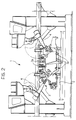
- a conveyor line 2 passes through the station 1 and transports a plurality of bodies to be welded through the station in succession.
- the bodies arrive in the station in a preassembled condition in which their components have been connected loosely, for example, by the bending of sheet-metal tabs which interconnect the components. For this reason, the body components have to be clamped in their exact positions of assembly during welding.
- two frames 3 are provided on the two sides of the line 2 in the welding station 1 and carry a plurality of clamping fixtures 3a (some of which are visible in the drawings) including locating elements and clamps which engage the various components of the body when it is in the working position in the welding station 1 in order to keep them in the correct positions of assembly during welding.
- the welding is carried out by a plurality of programmable robots 4 with welding heads (not shown) which perform a series of spot-welds which suffice to fix the geometry of the body.
- the two frames 3 which carry the locating and clamping fixtures 3a are pivotable about respective upper longitudinal axes 5 between substantially vertical positions (shown in continuous outline in Figure 1) in which the fixtures 3a can engage the body, and positions (shown in broken outline and indicated by the arrows D) in which they are opened out and the fixtures 3a are spaced from the body so that the welded body can leave the station and a new body can enter the station for welding.
- the two frames 3 are also slidable along upper longitudinal guides 6 so that they can be exchanged rapidly with a second pair of frames 3 (not visible in the drawings) adapted for working on a different type of body.
- the same welding station can thus work on various body types.
- all the characteristics described above are known from the Applicant's prior patent mentioned above. Further details concerning the construction and advantages of this arrangement can therefore be obtained directly from that patent.
- each orientable television camera 7 is carried by an arm 8 which is rotatable about an axis 9 relative to an auxiliary support structure 10 which is in turn rotatable relative to a further structure 12 about an axis 11 perpendicular to the axis 10.
- the electric motors for rotating the arm 8 and the auxiliary structure 10 are indicated 13, 14 respectively.
- the structure 12 in turn is mounted for rotation about an axis 15 parallel to the axis 9 on a support device 16 articulated to the wrist 18 of the robot about an axis 17.
- the structure 16 has a part 16a which is connected permanently to the robot's wrist and a part 16b which is connected releasably to the part 16a.
- the structural details of the means used for this connection are of known type and do not fall within the scope of the present invention. For this reason, these details have been omitted from the appended drawings which also makes the latter simpler and easier to understand.
- the structure 16 can be produced according to the prior art relating to robots with devices for exchanging their tools. According to this prior art, a robot can replace its own tool.
- the robot 4 can disengage the welding head at the surface 16c where it is connected to the part 16a and then equip itself with the entire adjustable structure, indicated 19 in the drawing, which carries the television camera 7.
- the television camera is connected to means for processing its output signals including, for example, a display terminal 20.
- one or more robots replace their welding heads with orientable television cameras 7 and bring the television cameras into correspondence with the fixtures 3a (see Figure 4 which is a magnified view of the detail IV of Figure 1) so that the configuration and/or positioning of the fixtures can be checked.
- Figure 4 which is a magnified view of the detail IV of Figure 1
- the checking operation does not involve any wastage of time by skilled personnel or difficulties resulting from difficult access to the fixtures for the personnel.
Landscapes
- Engineering & Computer Science (AREA)
- Mechanical Engineering (AREA)
- Chemical & Material Sciences (AREA)
- Optics & Photonics (AREA)
- Robotics (AREA)
- Manufacturing & Machinery (AREA)
- Physics & Mathematics (AREA)
- Combustion & Propulsion (AREA)
- Transportation (AREA)
- Automatic Assembly (AREA)
- Manipulator (AREA)
- Resistance Welding (AREA)
- Automobile Manufacture Line, Endless Track Vehicle, Trailer (AREA)
- Casings For Electric Apparatus (AREA)
Claims (3)
- Station (1) zum Montieren von Konstruktionen aus gepreßtem Blech, beispielsweise Kraftfahrzeug-Karosserien, mit Halteeinrichtungen (3a) zum Lokalisieren und Festspannen der verschiedenen Bestandteile der Konstruktionen im montierten Zustand und mit programmierbaren Robotern (4) mit elektrischen Punktschweißköpfen,
dadurch gekennzeichnet, daß- wenigstens einer der programmierbaren Roboter (4) eine Einrichtung zum Austauschen seines Schweißkopfes gegen einen Sensor (7) umfaßt, der zur Erzeugung jeweiliger Ausgangssignale ausgebildet ist, die die Position und/oder die Konfiguration der Halteeinrichtungen (3a) anzeigen,- wobei der Sensor (7) an eine Verarbeitungseinrichtung (20) angeschlossen ist, der die jeweiligen Ausgangssignale zugeführt werden, so daß die Position und/oder die Konfiguration der Halteeinrichtungen (3a) unter Verwendung des Roboters (4) der Schweißstation (1) geprüft werden kann. - Montagestation nach Anspruch 1, dadurch gekennzeichnet, daß der Sensor durch eine einstellbare, an eine Einrichtung (20) zum Verarbeiten ihrer Ausgangssignale angeschlossene Fernsehkamera (7) gebildet ist.
- Montagestation nach Anspruch 2, dadurch gekennzeichnet, daß die Fernsehkamera (7) von einem Arm (8) gehalten ist, der zwecks Drehung um eine Achse (9) an einer Hilfs-Halteanordnung (10) befestigt ist, die ihrerseits zwecks Drehung um eine zur Achse (9) senkrechte Achse (11) an einer weiteren Anordnung (12) befestigt ist, welche weitere Anordnung (12) zwecks Drehung um eine zur Drehachse (9) des Arms (8) parallele Achse (15) relativ zu einer weiteren, mit dem Handgelenk (18) des Roboters lösbar verbundenen Halte-Anordnung (16b) montiert ist.
Applications Claiming Priority (2)
| Application Number | Priority Date | Filing Date | Title |
|---|---|---|---|
| IT6744090 | 1990-06-15 | ||
| IT06744090A IT1248419B (it) | 1990-06-15 | 1990-06-15 | Stazione di assemblaggio di struttura di lamiera stampata provvista di robot di saldatura utilizzabili anche per il controllo periodico delle attrezzature utilizzate nella stazione. |
Publications (2)
| Publication Number | Publication Date |
|---|---|
| EP0464004A1 EP0464004A1 (de) | 1992-01-02 |
| EP0464004B1 true EP0464004B1 (de) | 1994-07-27 |
Family
ID=11302403
Family Applications (1)
| Application Number | Title | Priority Date | Filing Date |
|---|---|---|---|
| EP91830253A Expired - Lifetime EP0464004B1 (de) | 1990-06-15 | 1991-06-11 | Station zur Montage einer Struktur aus gepresstem Blech mit Schweissrobotern, auch benützbar zur Prüfung der in der Station benützten Halter |
Country Status (5)
| Country | Link |
|---|---|
| US (1) | US5258598A (de) |
| EP (1) | EP0464004B1 (de) |
| DE (1) | DE69103098T2 (de) |
| ES (1) | ES2056621T3 (de) |
| IT (1) | IT1248419B (de) |
Families Citing this family (16)
| Publication number | Priority date | Publication date | Assignee | Title |
|---|---|---|---|---|
| US5493093A (en) * | 1992-07-09 | 1996-02-20 | Cecil; Dimitrios G. | Computer-integrated multi-gun welding system |
| US5632912A (en) * | 1995-06-16 | 1997-05-27 | Cecil; Dimitrios G. | Resistance projection welding system and method for welding a projection weld nut to a workpiece |
| DE19806963A1 (de) * | 1997-03-22 | 1998-10-08 | Thyssen Industrie | Verfahren und Vorrichtung zum Zuführen, Spannen und Bearbeiten, insbesondere zum Geometrie-Schweißen von Bauteilen von Fahrzeugkarosserien in einer Bearbeitungsstation |
| EP0927598A1 (de) * | 1997-12-18 | 1999-07-07 | COMAU S.p.A. | GT Vorrichtung zum Punktschweissen von Kraftfahrzeugkarosserien oder ihre Anordnung |
| US6173881B1 (en) * | 1998-11-11 | 2001-01-16 | Progressive Tool & Industries Company | Car body assembly and welding station with reciprocal gate-supporting system |
| JP3663984B2 (ja) * | 1999-08-06 | 2005-06-22 | 日産自動車株式会社 | 車体組立方法および車体組立装置 |
| US6278077B1 (en) | 1999-12-02 | 2001-08-21 | Dimitrios G. Cecil | Weld indexing method and system |
| US6932263B2 (en) * | 2002-04-08 | 2005-08-23 | Progressive Tool & Industries Co. | Vehicle framing system for plurality of vehicle body styles |
| DE10258633A1 (de) * | 2002-12-16 | 2004-07-08 | Kuka Roboter Gmbh | Verfahren und Vorrichtung zum Positionieren von zusammenzufügenden Bauteilen |
| JP4350441B2 (ja) * | 2003-07-04 | 2009-10-21 | 本田技研工業株式会社 | 部品搬送・取付方法およびその装置 |
| DE10348500B4 (de) * | 2003-10-18 | 2009-07-30 | Inos Automationssoftware Gmbh | Verfahren und Vorrichtung zum Erfassen eines Spaltmaßes und/oder eines Versatzes zwischen einer Klappe eines Fahrzeugs und der übrigen Fahrzeugkarosserie |
| US20050189399A1 (en) * | 2004-02-26 | 2005-09-01 | Progressive Tool & Industries, Co. | Flexible body workstation for assembling workpieces |
| JP2011148010A (ja) * | 2010-01-19 | 2011-08-04 | Yaskawa Electric Corp | ポジショナを備えたロボットシステム |
| US11254381B2 (en) * | 2018-03-19 | 2022-02-22 | Divergent Technologies, Inc. | Manufacturing cell based vehicle manufacturing system and method |
| CN109318231A (zh) * | 2018-10-09 | 2019-02-12 | 厦门攸信信息技术有限公司 | 一种数码产品全自动化装配的柔性实现方法与系统 |
| CN111469168B (zh) * | 2020-05-19 | 2025-05-13 | 苏州市职业大学 | 一种仿生青蛙机器人组装定位用夹具 |
Family Cites Families (7)
| Publication number | Priority date | Publication date | Assignee | Title |
|---|---|---|---|---|
| DE147530C (de) * | ||||
| US4447697A (en) * | 1978-03-28 | 1984-05-08 | Unimation, Inc. | Weld gun repositioning system for programmable manipulator |
| GB2059303B (en) * | 1979-09-25 | 1983-06-02 | Nissan Motor | Two-shift automatic assembling apparatus |
| US4492847A (en) * | 1981-09-30 | 1985-01-08 | Unimation, Inc. | Manipulator welding apparatus with sensing arrangements for weld slam tracking |
| DE3342570C2 (de) * | 1983-11-25 | 1986-07-10 | Thyssen Maschinenbau GmbH Nothelfer-Ravensburg, 7980 Ravensburg | Verfahren zum Befestigen einer Tür an einer Karosserie eines Kraftfahrzeuges und Vorrichtung zum Durchführen dieses Verfahrens |
| GB8426225D0 (en) * | 1984-10-17 | 1984-11-21 | Plessey Co Plc | Robot machines |
| JPS6245483A (ja) * | 1985-08-23 | 1987-02-27 | Toyota Motor Corp | スポツト溶接用ロボツトの姿勢制御装置 |
-
1990
- 1990-06-15 IT IT06744090A patent/IT1248419B/it active IP Right Grant
-
1991
- 1991-06-11 ES ES91830253T patent/ES2056621T3/es not_active Expired - Lifetime
- 1991-06-11 DE DE69103098T patent/DE69103098T2/de not_active Expired - Fee Related
- 1991-06-11 EP EP91830253A patent/EP0464004B1/de not_active Expired - Lifetime
- 1991-06-13 US US07/714,451 patent/US5258598A/en not_active Expired - Fee Related
Also Published As
| Publication number | Publication date |
|---|---|
| ES2056621T3 (es) | 1994-10-01 |
| IT1248419B (it) | 1995-01-16 |
| EP0464004A1 (de) | 1992-01-02 |
| IT9067440A1 (it) | 1991-12-15 |
| DE69103098D1 (de) | 1994-09-01 |
| IT9067440A0 (it) | 1990-06-15 |
| US5258598A (en) | 1993-11-02 |
| DE69103098T2 (de) | 1995-01-05 |
Similar Documents
| Publication | Publication Date | Title |
|---|---|---|
| US5258598A (en) | Station for assembling pressed sheet-metal structures with welding robots also usable periodically for checking the fixtures used in the station | |
| JP3318618B2 (ja) | 変形応力を伴わずに組立部品の組立を行なうための方法並びにプログラマブルポジショナ | |
| EP0346816B1 (de) | Verfahren zum Zusammenbau eines Fahrzeugaufbaus | |
| US7653977B2 (en) | System and method for machining body parts, wherein robots are synchronised with a conveyor belt | |
| CN106216927B (zh) | 跨龙门罐体机器人焊接系统 | |
| CN111590226A (zh) | 一种汽车车身侧围外板总成的焊接产线 | |
| CN210172874U (zh) | 一种转向架构架自动化焊接系统 | |
| EP0350000B1 (de) | Vorrichtung zum Auftragsschweissen der Schaufelspitzen von Turbinen- und Kompressor-Schaufeln | |
| JP2017019053A (ja) | ロボット接合システム | |
| KR20210107956A (ko) | 선박 용접용 이동로봇 | |
| CN216066077U (zh) | 一种上、下桅杆自动化焊接生产线装置 | |
| CN110919247B (zh) | 一种轮毂焊接系统 | |
| EP0985485B1 (de) | Laserschweissmaschine zum Schweissen von Profilen auf grossformatigen Strukturbauteilen | |
| US5159844A (en) | Method and a device for checking fixtures used in machines or stations in production lines or installations | |
| CN217044463U (zh) | 箱体框架的组装系统 | |
| CN214602673U (zh) | 一种小钢瓶全自动环缝焊接设备 | |
| CN215359254U (zh) | 一种线切割机 | |
| CN113251066B (zh) | 一种法兰座及其制造方法、起重机械 | |
| EP0368389B1 (de) | System zum Schweissen von aus Blech bestehenden Strukturen mit vorpositionierten Geräten | |
| KR100208146B1 (ko) | 공작물 부착용 진공컵 조정기구 | |
| CN224254438U (zh) | 一种自动化视觉检测的汽车锻压件凸焊加工中心 | |
| CN213969748U (zh) | 一种焊接平台及焊接设备 | |
| CN110977223A (zh) | 寻缝视觉引导焊接方法 | |
| CN221389327U (zh) | 一种超声波自动焊接设备 | |
| CN220548293U (zh) | 一种具有多轴传动的焊接机器人 |
Legal Events
| Date | Code | Title | Description |
|---|---|---|---|
| PUAI | Public reference made under article 153(3) epc to a published international application that has entered the european phase |
Free format text: ORIGINAL CODE: 0009012 |
|
| AK | Designated contracting states |
Kind code of ref document: A1 Designated state(s): BE DE ES FR GB SE |
|
| 17P | Request for examination filed |
Effective date: 19920222 |
|
| 17Q | First examination report despatched |
Effective date: 19930304 |
|
| GRAA | (expected) grant |
Free format text: ORIGINAL CODE: 0009210 |
|
| AK | Designated contracting states |
Kind code of ref document: B1 Designated state(s): BE DE ES FR GB SE |
|
| REF | Corresponds to: |
Ref document number: 69103098 Country of ref document: DE Date of ref document: 19940901 |
|
| REG | Reference to a national code |
Ref country code: ES Ref legal event code: FG2A Ref document number: 2056621 Country of ref document: ES Kind code of ref document: T3 |
|
| ET | Fr: translation filed | ||
| EAL | Se: european patent in force in sweden |
Ref document number: 91830253.0 |
|
| PGFP | Annual fee paid to national office [announced via postgrant information from national office to epo] |
Ref country code: GB Payment date: 19950512 Year of fee payment: 5 |
|
| PGFP | Annual fee paid to national office [announced via postgrant information from national office to epo] |
Ref country code: SE Payment date: 19950524 Year of fee payment: 5 |
|
| PGFP | Annual fee paid to national office [announced via postgrant information from national office to epo] |
Ref country code: DE Payment date: 19950529 Year of fee payment: 5 |
|
| PGFP | Annual fee paid to national office [announced via postgrant information from national office to epo] |
Ref country code: BE Payment date: 19950530 Year of fee payment: 5 |
|
| PLBE | No opposition filed within time limit |
Free format text: ORIGINAL CODE: 0009261 |
|
| STAA | Information on the status of an ep patent application or granted ep patent |
Free format text: STATUS: NO OPPOSITION FILED WITHIN TIME LIMIT |
|
| PGFP | Annual fee paid to national office [announced via postgrant information from national office to epo] |
Ref country code: ES Payment date: 19950612 Year of fee payment: 5 |
|
| PGFP | Annual fee paid to national office [announced via postgrant information from national office to epo] |
Ref country code: FR Payment date: 19950630 Year of fee payment: 5 |
|
| 26N | No opposition filed | ||
| PG25 | Lapsed in a contracting state [announced via postgrant information from national office to epo] |
Ref country code: GB Effective date: 19960611 |
|
| PG25 | Lapsed in a contracting state [announced via postgrant information from national office to epo] |
Ref country code: SE Effective date: 19960612 Ref country code: ES Free format text: LAPSE BECAUSE OF EXPIRATION OF PROTECTION Effective date: 19960612 |
|
| PG25 | Lapsed in a contracting state [announced via postgrant information from national office to epo] |
Ref country code: BE Effective date: 19960630 |
|
| BERE | Be: lapsed |
Owner name: COMAU S.P.A. Effective date: 19960630 |
|
| GBPC | Gb: european patent ceased through non-payment of renewal fee |
Effective date: 19960611 |
|
| PG25 | Lapsed in a contracting state [announced via postgrant information from national office to epo] |
Ref country code: FR Effective date: 19970228 |
|
| PG25 | Lapsed in a contracting state [announced via postgrant information from national office to epo] |
Ref country code: DE Effective date: 19970301 |
|
| EUG | Se: european patent has lapsed |
Ref document number: 91830253.0 |
|
| REG | Reference to a national code |
Ref country code: FR Ref legal event code: ST |
|
| REG | Reference to a national code |
Ref country code: ES Ref legal event code: FD2A Effective date: 19990601 |