EP0463992B1 - Safety razor - Google Patents
Safety razor Download PDFInfo
- Publication number
- EP0463992B1 EP0463992B1 EP91810461A EP91810461A EP0463992B1 EP 0463992 B1 EP0463992 B1 EP 0463992B1 EP 91810461 A EP91810461 A EP 91810461A EP 91810461 A EP91810461 A EP 91810461A EP 0463992 B1 EP0463992 B1 EP 0463992B1
- Authority
- EP
- European Patent Office
- Prior art keywords
- flat
- application
- preparation
- applicator
- contour
- Prior art date
- Legal status (The legal status is an assumption and is not a legal conclusion. Google has not performed a legal analysis and makes no representation as to the accuracy of the status listed.)
- Expired - Lifetime
Links
Images


Classifications
-
- B—PERFORMING OPERATIONS; TRANSPORTING
- B26—HAND CUTTING TOOLS; CUTTING; SEVERING
- B26B—HAND-HELD CUTTING TOOLS NOT OTHERWISE PROVIDED FOR
- B26B21/00—Razors of the open or knife type; Safety razors or other shaving implements of the planing type; Hair-trimming devices involving a razor-blade; Equipment therefor
- B26B21/40—Details or accessories
- B26B21/44—Means integral with, or attached to, the razor for storing shaving-cream, styptic, or the like
- B26B21/446—Shaving aid stored in the razor handle
-
- B—PERFORMING OPERATIONS; TRANSPORTING
- B05—SPRAYING OR ATOMISING IN GENERAL; APPLYING FLUENT MATERIALS TO SURFACES, IN GENERAL
- B05B—SPRAYING APPARATUS; ATOMISING APPARATUS; NOZZLES
- B05B11/00—Single-unit hand-held apparatus in which flow of contents is produced by the muscular force of the operator at the moment of use
- B05B11/0005—Components or details
-
- B—PERFORMING OPERATIONS; TRANSPORTING
- B05—SPRAYING OR ATOMISING IN GENERAL; APPLYING FLUENT MATERIALS TO SURFACES, IN GENERAL
- B05B—SPRAYING APPARATUS; ATOMISING APPARATUS; NOZZLES
- B05B11/00—Single-unit hand-held apparatus in which flow of contents is produced by the muscular force of the operator at the moment of use
- B05B11/01—Single-unit hand-held apparatus in which flow of contents is produced by the muscular force of the operator at the moment of use characterised by the means producing the flow
- B05B11/10—Pump arrangements for transferring the contents from the container to a pump chamber by a sucking effect and forcing the contents out through the dispensing nozzle
- B05B11/1028—Pumps having a pumping chamber with a deformable wall
- B05B11/1032—Pumps having a pumping chamber with a deformable wall actuated without substantial movement of the nozzle in the direction of the pressure stroke
Landscapes
- Life Sciences & Earth Sciences (AREA)
- Forests & Forestry (AREA)
- Engineering & Computer Science (AREA)
- Mechanical Engineering (AREA)
- Dry Shavers And Clippers (AREA)
Abstract
Description
Die Erfindung liegt auf dem Gebiete der Körperpflege und betrifft ein Rasiergerät zur Feuchtrasur (Klingenrasur) gemäss dem Oberbegriff der unabhängigen Patentansprüche, mit welcher Haare an beliebigen Körperstellen (Flächen-, Rundungs- oder Konturrasur) unter Verwendung eines beliebigen Präparats (bspw. Problemrasur), das durch das Gerät während der Rasur aufgetragen wird, hautnah abgeschnitten werden können.The invention is in the field of personal care and relates to a shaving device for wet shaving (blade shaving) according to the preamble of the independent claims, with which hair on any part of the body (surface, rounding or contour shaving) using any preparation (for example problem shaving), that is applied by the device while shaving, can be cut off very close.
Vor einer Klingenrasur, ob frauen- oder männerspezifisch, muss in der Regel ein Gleit- und Weichmittel (allfällige Problemrasur) auf die Hautoberfläche aufgetragen werden. Die flächige Applikation dünner Schichten von solchen kosmetischen (gegebenenfalls pharmazeutischen) Präparaten auf die Haut, wird meist von Hand durchgeführt oder aber durch einen Sprühvorgang. Dabei ist eine gute Dosierung und eine sehr regelmässige Verteilung schwierig. Es ist unvermeidbar, dass ein Teil des zu applizierenden, mitunter teuren Präparates auf der applizierenden Hand verbleibt. Ferner sind Spraydosen, mit denen das Applikationsproblem auch nicht gelöst wird, wegen Umweltverschmutzung nicht mehr erwünscht. Zudem bleibt bei der bekannten Art von Klingenrasur stets das Hygieneproblem aktuell.Before a blade shave, whether specific to women or men, a lubricant and softener (any problem shave) must be applied to the skin surface. The flat application of thin layers of such cosmetic (possibly pharmaceutical) preparations to the skin is usually carried out by hand or by spraying. A good dosage and a very regular distribution is difficult. It is unavoidable that part of the sometimes expensive preparation to be applied remains on the application hand. Furthermore, spray cans with which the application problem is also not solved are no longer desirable because of environmental pollution. In addition, with the known type of blade shaving, the hygiene problem always remains current.
So werden zum Beispiel kombinierte Präparate zur Behandlung von Körperhaar vor dem Rasieren und der frischrasierten Haut nach dem Rasieren von der kosmetischen Industrie entwickelt und dauernd verbessert. Solche Präparate werden in Form einer Flüssigkeit, Creme oder Schaum vor dem Rasieren meist von Hand auf der Haut verteilt. Dies bedeutet einen Arbeitsgang vor dem Rasieren und eine sehr erwünschte sparsame Dosierung ist eigentlich nicht möglich. Dies ist vor allem ein Nachteil bei Verwendung von neueren Präparaten, die derart wirksam sind, dass schon sehr kleine Mengen, beispielsweise 150 bis 250mgr, für eine Rasur vollauf genügen können. Es ist kaum möglich, eine so kleine Menge von Hand regelmässig zu verteilen.For example, combined preparations for the treatment of body hair before shaving and freshly shaved skin after shaving are developed and continuously improved by the cosmetic industry. Such preparations are usually applied to the skin by hand in the form of a liquid, cream or foam before shaving. This means one step before shaving and a very desirable economical dosage is actually not possible. This is above all a disadvantage when using newer preparations which are so effective that even very small amounts, for example 150 to 250 mgr, can be sufficient for a shave. It is hardly possible to distribute such a small amount regularly by hand.
Es sind schon früh Vorrichtungen entwickelt worden, die es erlauben, Hautpräparate während des Rasierens automatisch auf die Haut zu verteilen. Allerdings beziehen sich diese Vorrichtungen ausschliesslich auf männerspezifisches Rasieren. Es ist zum Beispiel in den U.S. Patentschriften 4,074,429, 4,381,293 und 4,562,644 vorgeschlagen worden, ein Hautpräparat in fester Form derart am Rasierkopf anzubringen, dass es beim Rasieren vor der Klinge oder den Klingen über die Haut gezogen wird, wobei ein dünner Film des Präparates auf die Haut abgerieben wird. Das feste Präparat verändert jedoch durch den Verbrauch seine Form und muss deshalb in seiner Position gegenüber der Klinge oft ajustiert werden, ausserdem muss das Präparat, wie gesagt, für die Formhaltung eine feste Konsistenz aufweisen.Devices that allow skin preparations to be automatically distributed to the skin during shaving have been developed at an early stage. However, these devices only relate to men's shaving. For example, in U.S. Patents 4,074,429, 4,381,293 and 4,562,644 have been proposed to attach a skin preparation in solid form to the razor head in such a way that it is pulled over the skin when shaving in front of the blade or blades, a thin film of the preparation being rubbed onto the skin. However, the solid preparation changes its shape due to consumption and therefore often has to be adjusted in its position in relation to the blade. Furthermore, as stated, the preparation must have a firm consistency for the shape retention.
Ferner ist vorgeschlagen worden, flüssige oder schaumförmige Präparate mit am Rasierkopf befestigten Teilen aus schwammartigem Material (U.S Patentschriften 3,895,437 und 4,314,404) oder mit entsprechenden Gummirollen (U.S Patentschriften 2,677,883 und 2,861,338) zu applizieren. Auch mit diesen Vorrichtungen ist es schwierig, einen regelmässigen Präparatefilm auf die Haut zu bringen. Bei diesen Vorrichtungen wird ein Behälterteil mit einem flüssigen oder schaumförmigen Präparat gefüllt, das mit dem Applikationsteil auf die Haut gebracht wird. Es wird also kein frisches Fluid zugeführt, sondern in einer Art Recycling das zum Teil verbrauchte Fluid wieder zum Einsatz gebracht. Nach dem Rasieren wird der Rest des Präparates zusammen mit verbrauchtem Präparat mittels Spülen entfernt. Hauptzweck dieser Vorrichtungen ist das Vermeiden eines dem Rasieren vorangehenden Behandlungsvorganges. Es sind somit keine Dosier-/Applikationsvorrichtungen und das Hygieneproblem bleibt zudem ungelöst.It has also been proposed to apply liquid or foam-like preparations with parts made of sponge-like material attached to the razor head (US Pat. Nos. 3,895,437 and 4,314,404) or with corresponding rubber rollers (US Patents 2,677,883 and 2,861,338). Even with these devices, it is difficult to put a regular preparation film on the Bring skin. In these devices, a container part is filled with a liquid or foam-like preparation which is brought onto the skin with the application part. This means that no fresh fluid is supplied, but rather that the partially used fluid is used again in a kind of recycling. After shaving, the rest of the preparation is removed by rinsing together with the used preparation. The main purpose of these devices is to avoid a pre-shaving treatment. There are therefore no dosing / application devices and the hygiene problem remains unsolved.
Aus der GB-A-488,143 ist eine Vorrichtung zur Flächen- und/oder Konturrasur bekannt, bei der ein dünner Film eines Präparates unter Druck aus einem Fluidkanal direkt über eine spaltförmige Applikationsöffnung vor der Schneide auf die Haut aufgebracht wird. Doch wird bei dieser Lösung eine einwandfreies Auftragen und Verteilen der Fluidschicht nicht gewährleistet.From GB-A-488,143 a device for surface and / or contour shaving is known, in which a thin film of a preparation is applied to the skin directly under pressure from a fluid channel via a gap-shaped application opening in front of the cutting edge. With this solution, however, proper application and distribution of the fluid layer is not guaranteed.
Alle diese Ansätze mangeln des richtigen Zusammenspiels zwischen dem Rasierpäparat, dessen Zuführung zur Rasier-Vorrichtung und dem Klingenteil. Das ledigliche Hinzufügen eines beliebigen Teils von Präparat während eines Rasiervorganges ist unzureichend. Insbesondere dann, wenn an schon bestehende Rasiergeräte solche Zusatzmechanismen angeordnet werden. Für das richtige Zusammenspiel braucht es ein vollständig neues Gerät mit aufeinander abgestimmten Funktionsteilen.All of these approaches lack the correct interplay between the shaving preparation, its delivery to the shaving device and the blade part. The mere addition of any part of the preparation during a shaving process is insufficient. Especially when such additional mechanisms are arranged on existing shavers. For the correct interaction, a completely new device with coordinated functional parts is required.
Es ist nun die Aufgabe der Erfindung, ein solches Gerät zu schaffen, mit dessen Hilfe ein pumpbares Präparat als dünne, regelmässige Schicht flächig und schneidgerecht appliziert werden kann. Die Zufuhr von Präparat zur Applikation soll nur während des Applikations- oder Pumpvorganges möglich sein. Wird nicht appliziert, sollen sämtliche Zufuhrwege automatisch unterbrochen und abgeschirmt sein. Es soll aus hygienischen Gründen verhindert werden, dass Verunreinigungen von aussen in das vorrätige Präparat eingeschleppt werden. Es soll für den Anwender leicht möglich sein, das Präparat genau zu dosieren. Die Vorrichtung soll sich für frauen- wie für männerspezifisches Rasieren eignen. Beim frauenspezifischen Rasieren sind Flächen mit stärkeren Rundungen, also ein Rundungsrasieren (konkav und konvex) erforderlich, während beim männerspezifischen Rasieren vorwiegend Flächen mit weniger starken Rundungen im Vordergrund stehen. Doch seit jeher ist auch beim männerspezifischen Rasieren das sogenannte "Grübchenproblem" jeweils Thema gewesen und es ist nicht zuletzt auf die Erfordernisse des frauenspezifischen Rasierens zurückzuführen, dass auch diese Problemstellungen des Männerrasierens lösbar werden.It is now the object of the invention to provide such a device with the aid of which a pumpable preparation can be applied as a thin, regular layer over a wide area and in a manner suitable for cutting. The supply of preparation for application should only be possible during the application or pumping process be. If not applied, all feed routes should be automatically interrupted and shielded. For hygienic reasons, it should be prevented that contaminants are brought into the preparation from outside. It should be easy for the user to precisely dose the preparation. The device is said to be suitable for shaving for women as well as for men. For women-specific shaving, areas with greater curvatures, i.e. rounding shaving (concave and convex), are required, while for men-specific shaving, areas with predominantly less pronounced curves are in the foreground. But the so-called "dimple problem" has always been an issue for men-specific shaving and it is not least due to the requirements of women-specific shaving that these problems of male shaving can also be solved.
Die oben gestellte Aufgabe wird durch die Vorrichtung gemäss den kennzeichnenden Teilen der unabhängigen Patentansprüche gelöst. Die erfindungsgemässe Vorrichtung besteht aus einem Applikatorteil, einem Fluid-Speiseteil und einem Klingenteil. Die folgende Beschreibung und die dazugehörenden Figuren befassen sich zuerst generell mit dem Zusammenwirken von Applikatorteil und Klingenteil (Figur 1), dann im Detail mit dem Applikatorteil (Figuren 2 und 3), mit dem Speiseteil (Figuren 4 bis 8) und zuletzt mit der Integration des Klingenteils zu einem Rasiergerät gemäss Erfindung (Figuren 9 bis 14), in dem die drei Teile kombiniert miteinander zur Wirkung kommen.The above object is achieved by the device according to the characterizing parts of the independent claims. The device according to the invention consists of an applicator part, a fluid supply part and a blade part. The following description and the associated figures first deal generally with the interaction of the applicator part and the blade part (Figure 1), then in detail with the applicator part (Figures 2 and 3), with the feed part (Figures 4 to 8) and finally with the integration of the blade part to a razor according to the invention (Figures 9 to 14), in which the three parts come together to work.
Diese Kombination bewirkt ein neuartiges arbeitsmässiges Zusammenwirken von Klinge und Präparat bzw. ein funktionelles Zusammenwirken von in einem Reservoir hygienisch untergebrachtem Fluid (das Präparat), welches mittels eines Speiseteils an einen Applikatorteil geführt wird, welcher das Fluid dosierend am schneidrichtigen Ort auf die Haare verteilt und gleichzeitig die Schneidposition beeinflussend den Klingenteil in seiner Arbeit unterstützt. Beim Absetzen des Geräts wird die Fluidzufuhr unterbrochen und in einen wasch- oder spülbaren Zustand gebracht, wobei das Präparatereservoir gegen aussen abgeschirmt ist. Ohne zusätzliche Manipulationen ist das Gerät in einem hygienischen Zustand gleich wieder einsetzbar. Klingenteil und Applikatorteil sind formmässig aufeinander abgestimmt; der Speiseteil samt Reservoir ist auf den Applikatorteil funktionell abgestimmt, so, dass der Applikatorteil einerseits die Dosierung an den Klingenteil und die Abschirmung zum Speiseteil bewirkt. Dieses Zwischenglied ist trotz seiner Doppelfunktion vielfältig gestaltbar, kann jeder Klingenform angepasst werden und kontrolliert den zugepumpten Fluss des Fluids aus seinem Reservoir.This combination results in a novel working interaction of the blade and the preparation or a functional interaction of fluid (the preparation), which is hygienically housed in a reservoir, which is fed to an applicator part by means of a feed part, which distributes the fluid in a metering manner at the cutting location on the hair and at the same time influencing the cutting position supports the blade part in its work. When the device is set down, the fluid supply is interrupted and brought into a washable or rinsable state, the preparation reservoir being shielded from the outside. The device can be used again in a hygienic condition without any additional manipulation. The blade part and applicator part are formally matched to one another; the feed part including the reservoir is functionally matched to the applicator part, so that the applicator part on the one hand doses to the blade part and the shield to the dining area. Despite its double function, this intermediate link can be designed in many ways, can be adapted to any blade shape and controls the pumped-in flow of the fluid from its reservoir.
Vorzugsweise ist die Applikationsöffnung spaltförmig. Die die Offnung begrenzenden Elemente können beweglich oder starr sein. Sind sie beweglich, so kann die Beweglichkeit zur Applizierung (bspw. Rollen) oder zum Verkleinern bis Verdecken der Öffnung (bspw. Schwenkachse einer Rolle) oder für beides dienen. Die die Öffnung begrenzenden Elemente können so zum Klingenteil (eine oder mehrere Schneiden) angeordnet sein, dass das Schneiden mechanisch unterstützt wird, sodass der Geometrie von Schneide(n) und Öffnungsbegrenzungselement(en) eine zusätzliche Bedeutung zukommt. Die Applikationsöffnung ist ihrerseits über den Speiseteil mit dem Fluidreservoir verbunden, das durch den Speisekanal und die Begrenzungselemente abgeschirmt ist, um den Hygieneanforderungen zu genügen. Dazu gehört auch, dass der Speiseteil nur in einer Richtung, die Abgaberichtung nämlich, arbeitet. Das nachdrängende Fluid "säubert" den/die Zufuhrungskanal/-kanäle von infiltrierenden Anteilen, ist aber durch die integrierte Dosierung trotzdem sparsam. Auch hier ist durch die zwangsläufige Abgaberichtung und durch die Dosierungsfähigkeit des Gerätes ein Doppelnutzen zu vermerken.The application opening is preferably slit-shaped. The elements delimiting the opening can be movable or rigid. If they are movable, the mobility can be used for application (for example, rollers) or for shrinking to cover the opening (for example, swivel axis of a roller) or for both. The elements delimiting the opening can be arranged in relation to the blade part (one or more cutting edges) in such a way that the cutting is mechanically supported, so that the geometry of the cutting edge (s) and opening limiting element (s) is of additional importance. The application opening is in turn connected via the feed part to the fluid reservoir, which is shielded by the feed channel and the delimiting elements, in order to meet the hygiene requirements. This also means that the feed section only works in one direction, namely the delivery direction. The urging fluid "cleans" the infiltrating parts of the supply channel (s), but is nevertheless economical due to the integrated dosage. Here too, a double benefit is noted due to the inevitable dispensing direction and the metering ability of the device.
Die folgenden Figuren dienen der generellen Beschreibung der Fluidzuführung zu einem Klingenteil, dabei zeigen:
- Fig. 1.1
- ein generelles Prinzipschema,
- Fig. 1.2
- dasselbe für eine Ausführungsform mit Applikationsrolle,
- Fig. 1.3
- ein schematisches, erfindungsgemässes Rasiergerät.
- Fig. 1 . 1
- a general principle,
- Fig. 1.2
- the same for an embodiment with an application roller,
- Fig. 1.3
- a schematic, shaving device according to the invention.
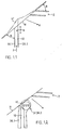
Fig. 1.1 zeigt eine abstrahierte Prinzipdarstellung der Speise-, Applikations- und Schneidfunktion eines Rasiergerätes. Mit α ist ein Applikationswinkel und mit β ein Schneidwinkel bezeichnet, wobei für ein störungsfreies Rasieren der Winkel α grösser ist als der Winkel β. Die beiden Winkel beziehen sich auf die Hautoberfläche H. Zwischen den die beiden Winkel zur Haut definierenden Geräteteilen, Klingen 2 und äussere Fluidkanalbegrenzung 30. 1, ist ein den Schneidwinkel beeinflussender Applikatorteil (Manipulationsteil) 30.2 angeordnet, der einerseits die Applikationsöffnung klingenseitig begrenzender und wahlweise den Fluidkanal 10 verschliessender Teil ist. Ein gekreuzter Doppelpfeil zeigt die Verstellmöglichkeiten. In Richtung Hautoberfläche geschoben, bewirkt er ein lokales Zurückschieben der Hautoberfläche H in die Position H′. Zwischen Klinge 2 und dem Manipulationsteil 30.2 kann sich der Abschab A, das sind Haare und Abrieb von Präparat und Haut, entfernen. Im Fluidkanal wird das Fluid unter einem bestimmten Pumpdruck zum Applikatorteil gefördert (Pfeil p) und tritt an der Applikationsöffnung im Bereich der Hautoberfläche aus. Wird der Klingenteil in Schneidrichtung bewegt, so verteilt der Applikatorteil das Präparat auf die Hautoberfläche. 1.1 shows an abstracted schematic representation of the feeding, application and cutting function of a shaving device. An application angle is designated by α and a cutting angle is designated by β, the angle α being greater than the angle β for trouble-free shaving. The two angles relate to the skin surface H. Between the device parts defining the two angles to the skin,
Fig. 1.2 zeigt eine erfindungsgemässe Ausführungsform, bei welcher der Fluidkanal 10 des Applikatorteils durch einen rollenförmigen Zusatz an den Wandteilen 30.1, 30.2 verschlossen oder zumindest verengt werden kann. Der den Schneidwinkel beeinflussende Applikatorteil 30.2 (Manipulationsteil) ist beispielsweise eine zylinderförmige Rolle 3, die einerseits die Applikationsöffnung klingenseitig begrenzt und durch ihre Position den Fluidkanal partiell abdeckt. Es sind durch einen Doppelpfeil die Verstellmöglichkeiten angezeigt, falls die Rolle 3 in einem schlitzförmigen Lager gelagert ist. Je nach Position des schwenkbaren Rollenteils wird der Kanal mehr oder weniger abgedeckt. Je nach Rollendurchmesser wird die Hautoberfläche mehr oder weniger beeinflusst, das heisst, örtlich in eine Position H′ zurückgeschoben. Wird nun der rollenförmige Manipulatorteil 30.2 in eine Ruhelage gebracht, bei der die Austrittsöffnung des Fluidkanals 10 geschlossen ist, bspw. mittels Federdruck, so bewirkt eine Bewegung des Klingenteils in Schneidrichtung ein Öffnen desselben, sodass das unter Pumpdruck stehende Fluid ungehindert austreten kann. Gleichzeitig wird es vom Rollenteil 30.2 auf der Hautoberfläche verstrichen. FIG. 1.2 shows an embodiment according to the invention, in which the
Fig. 1.3 zeigt einen schematischen Schnitt durch eine beispielhafte Ausführungsform der erfindungsgemässen Vorrichtung, die aus den drei Teilen, nämlich aus einem Applikator, einer Schneidvorrichtung und einer Speisevorrichtung, aus der das Präparat in den Applikator gespeist wird, besteht. Der Applikator entspricht der Rollenlösung gemäss Figur 1.2. Die Schneidvorrichtung ist in den Applikator integriert, das heisst Schneidvorrichtung und Applikator bilden zusammen den Rasierkopf 1. Der Hauptbestandteil des Applikators ist eine parallel zu den Klingen 2 angeordnete Applikationsrolle 3. Die Speisevorrichtung ist im Handgriff 4 der Vorrichtung untergebracht und besteht aus einer kleinen Pumpe 5 und einem Reservoir 6. 1.3 shows a schematic section through an exemplary embodiment of the device according to the invention, which consists of the three parts, namely an applicator, a cutting device and a feed device from which the preparation is fed into the applicator. The applicator corresponds to the roller solution according to Figure 1.2. The cutting device is integrated in the applicator, that is to say the cutting device and applicator together form the shaving head 1. The main component of the applicator is an
Zum Rasieren wird der Rasierkopf 1 mit Hilfe des Handgriffes 4 derart über die Haut gezogen, dass die Applikationsrolle 3 unmittelbar vor den Klingen 2 über die Haut rollt. Die Pumpe 5 ist derart positioniert, dass sie zwischen Daumen und Zeigefinger liegt und, je nach Ausführungsform, durch leichtes alternierendes Drücken und Wieder-Loslassen betätigt werden kann. Dadurch wird Präparat aus dem Reservoir 6 in den Applikator gepumpt und als dünner Film auf die Applikationsrolle 3 verteilt und von dieser auf die Haut übertragen. Die Dosierung ist einfach. Eine zu knappe Dosierung wirkt sich durch Trockenlaufen der Applikationsrolle, eine zu starke Dosierung durch Tropfenbildung aus.For shaving, the shaving head 1 is pulled over the skin with the aid of the
Die folgenden Figuren dienen der Beschreibung des Applikatorteils.
- Fig. 2
- (a und b) zeigt eine Seitenansicht einer beispielhaften Ausführungsform eines Applikators gemäss Erfindung, bei dem ein separater Lagerteil besonders hervorgehoben ist;
- Fig. 3
- (a und b) zeigt Schnitte durch dieselbe Ausführungsform und durch eine weitere, in einen Rasierkopf integrierte Ausführungsform.
- Fig. 2
- (a and b) shows a side view of an exemplary embodiment of an applicator according to the invention, in which a separate bearing part is particularly emphasized;
- Fig. 3
- (a and b) shows sections through the same embodiment and through another embodiment integrated into a razor head.
Der Applikator besteht aus einer Applikationsrolle und einem Zuführsystem. Die Applikationsrolle wird für die Applikation zum Beispiel über die Haut gerollt. Sie ist bspw. dreh- und schwenkbar gelagert, so dass sie beim Abrollen in der einen Richtung (Applikationsrichtung R) ausgeschwenkt wird, während sie beim Abrollen in die andere Richtung und, wenn sie nicht rollt, in ihrer Ruhelage verbleibt. Durch das Ausschwenken wird es möglich, dass auf der Rollenoberfläche ein dünner Film von Präparat aus dem Zuführsystem gegen aussen mitgeführt wird. In Ruhestellung schirmt die Applikationsrolle das Zuführsystem gegen aussen ab. In einer anderen Ausführungsform ist die Applikationsrolle fix gelagert und die Spaltbreite bleibt konstant. Diese Ausführungsform eignet sich bei Präparaten, die nicht stark eintrocknen und nur zu geringer Filmbildung neigen. In einer weiteren Ausführungsform kann die Applikationsrolle auch nur schwenkbar, aber nicht drehbar gelagert sein, sodass sie die Applikationsöffnung verschliesst und frei gibt, für die Applikation selbst aber etwa in derselben Weise wirkt wie ein Applikationsspachtel, wie er im fogenden noch beschrieben werden soll.The applicator consists of an application roll and a feed system. The application roll is rolled over the skin for the application, for example. It is, for example, rotatably and pivotably mounted so that it is swiveled out in one direction (application direction R) when unrolling, while it remains in its rest position when unrolling in the other direction and, if it is not rolling. Swiveling out makes it possible for a thin film of preparation to be carried outwards from the feed system on the roll surface. In the rest position, the application roller shields the feed system from the outside. In another embodiment, the application roller is fixed and the gap width remains constant. This embodiment is suitable for preparations that do not dry out too much and tend to form little film. In a further embodiment, the application roller can also only be pivoted, but not rotatably, so that it closes and opens the application opening, but acts for the application itself in approximately the same way as an application spatula, as will be described below.
Fig. 2a zeigt einen Applikator von der Seite. Er besteht aus der Rolle 3, einem Kopfstück 21 und zwei seitlich vom Kopfstück 21 angebrachten Lagerteilen 22. Die Lager 23 in den Lagerteilen 22 sind entweder so gestaltet, dass sie nicht nur eine Drehung der Rolle 3 um ihre Drehachse, sondern auch ein Ausschwenken dieser Drehachse ermöglichen oder so, dass sie lediglich um ihre Drehachse bewegen. In der ersten Variante resultiert eine variable Applikationsspaltbreite und in der zweiten Variante eine fixe Applikationsspaltbreite. In Fig. 2b, die einen separaten Lagerteil 22 darstellt, ist ein Lager 23, das eine variable Applikationsspaltbreite ermöglicht, noch separat dargestellt. 2a shows an applicator from the side. It consists of the
Fig. 3a zeigt einen Schnitt durch den Kopfteil 21 der in Fig. 2a dargestellten Ausführungsform des Applikators. Eine Bohrung 31, die der Zufuhr des Präparates dient, verbindet das rollentragende Ende des Kopfteiles 21 mit seinem Anschlussende. Am Rollenende mündet die Bohrung in einen parallel, zur Rolle 3 verlaufenden, gegen die Rolle 3 offenen Kanal 32. Am Anschlussende ist die Bohrung entsprechend dem Anschluss an die Speisevorrichtung ausgestaltet. Auf beiden Seiten des Kanales 32 ist der Kopfteil zu Lippen 33.1 und 33.2 geformt. FIG. 3a shows a section through the
Die Lager der Rolle 3 in den Lagerteilen 22 (siehe Figur 2) sind, im Gegensatz zu einer fixen Rollenlagerung, derart gestaltet, dass die Rolle zwei extreme Schwenkpositionen einnehmen kann: eine "Ruhelage" (in der Figur ausgezogen dargestellt) und eine "Applikationslage" (in der Figur gestrichelt dargestellt). Wenn die Rolle 3 in ihrer Ruhelage ist, ist sowohl die Spalte A zwischen der Lippe 33.1 und der Rolle 3, als auch die Spalte C zwischen der Lippe 33.2 und der Rolle 3 derart schmal, dass kein Präparat austreten kann und der Kanal 32 und damit das Zuführsystem gegen aussen abgeschirmt ist. Wenn die Rolle 3 von der Ruhelage in die Applikationslage bewegt wird, verändert sich die Breite der Spalte A nicht, während sich die Spalte C verbreitert, bis in der Applikationslage ihre Breite der gewünschten Austrittsmenge für das Präparat entspricht. Die Applikationslage für eine gewünschte Austrittsmenge kann auch fix bleiben, sodass die Ruhelage der der Applikationslage entspricht. Die Abschirmung ist dann je nach Filmbildung gut oder besser, das Eintrocknen gut oder schlechter.In contrast to a fixed roller bearing, the bearings of the
Wird im Falle der Ausführungsform mit variablem Applikationsspalt die Rolle 3 in Applikationsrichtung über die Haut gezogen, wird sie durch die Reibung zwischen der Haut und der Rolle in der Richtung des Pfeiles R gedreht und dadurch in die Applikationslage ausgeschwenkt und in dieser gehalten. Wird die Rolle 3 in der dem Pfeile R entgegengesetzten Richtung gedreht, wird sie in die Ruhelage geschwenkt und in dieser gehalten. Ist die Rolle 3 in ihrer Applikationslage, wird aber nicht mehr in Applikationsrichtung gedreht, was unmittelbar nach dem Applizieren der Fall ist, wird sie durch die Oberflächenspannung der Präparateoberfläche im Spalt C gegen die Ruhelage zurückgezogen. Es werden also zum Wiederschliessen des Spaltes C nach der Applikation die physikalischen Eigenschaften des Präparates ausgenützt. Die Oberfläche steht unter einer Spannung, die die Oberfläche auf ein Minimum zu reduzieren versucht. Sind nun die Lager 23 derart ausgestaltet, dass die Lagerkräfte, die für eine Schwenkung der Rolle 3 überwunden werden müssen, kleiner als die aus der Oberflächenspannung resultierenden Kräfte, wird die Rolle gegen die Ruhelage bewegt, sobald sie nicht durch die Applikationsbewegung in die entgegengesetzte Richtung gedrückt wird. Wird der Applikator nach dem Schliessen des Spaltes C durch die Oberflächenspannung sich selber überlassen, bildet sich durch Eintrocknen der Präparateoberfläche im Spalt C eine Haut, die das restliche Präparat im Zufuhrsystem gegen aussen abschirmt. Diese Abschirmung ist genügend, um eine weitere Eintrocknung des Präparates zu verhindern und um das Präparat zum Beispiel gegen Oxydantien und Bakterien zu schützen. Bei einer erneuten Applikation wird die Haut, die den Spalt C bedeckt, sofort zerrissen und stört die Applikation in keiner Weise.If, in the case of the embodiment with a variable application gap, the
Versuche haben gezeigt, dass die physikalischen Eigenschaften einer grossen Zahl von handelsüblichen Hautpräparaten für das Rasieren den Anforderungen, die durch den beschriebenen Abschirmmechanismus gestellt werden, entsprechen, also für eine Anwendung im erfindungsgemässen Applikator, ob mit varaiblem oder mit fixem Applikationsspalt, geeignet sind.Experiments have shown that the physical properties of a large number of commercially available skin preparations for shaving meet the requirements set by the shielding mechanism described, i.e. are suitable for use in the applicator according to the invention, whether with a variable or with a fixed application gap.
Dadurch dass der Spalt A zwischen der Lippe 33.1 und der Rolle 3 in jeder Schwenkposition (offen/zu oder für, entsprechend offen) der Rolle 3 sehr klein ist, ist der Kanal 32 der Seite der Lippe 33.1 immer gegen aussen abgeschlossen. In Ruhelage und in Applikationslage der Rolle 3 kann dadurch kein Präparat in dieser Richtung nach aussen gelangen, in Applikationslage kann keine Verschmutzung, die die Rolle von der Haut mitträgt an der Lippe 33.1 vorbei in den Kanal 32 gelangen. Bei der Ausführungsform mit fixem Spalt ist dies nur abgeschwächt der Fall.Because the gap A between the lip 33.1 and the
Für zusätzlichen Schutz und Abschluss des Applikators kann er auch einen Deckel besitzen, der nach Beenden der Applikation auf den Applikator gesetzt wird und der derart geformt ist, dass er die Rolle 3 gegen die beiden Lippen 33.1 und 33.2 presst oder einfach nur den Applikationsspalt überdeckt. Ebenso können an Stelle einer Schutzkappe zusätzliche mechanische Anpressmittel, bspw. Federn vorgesehen sein, um die Applikationsrolle 3 gegen die Verschlusslippe zu pressen. Dies kann nötig sein, wenn bspw. ein solches Rasiergerät in Reiseausführungen starken Druckschwankungen ausgesetzt wird und man eine zusätzliche Verschlusskraft an der Vorrichtung wünscht.For additional protection and closure of the applicator, it can also have a lid which is placed on the applicator after the application has ended and which is shaped in such a way that it presses the
Fig 3b zeigt einen Schnitt durch die Ausführungsform des erfindungsgemässen Applikators mit variablem Spalt. Er zeigt dieselben Teile wie der in Fig. 3a dargestellte Applikator, auf seinem Kopfteil 21 ist aber ein Klingenträger 34 mit Klingen 2 mittels beispielsweise einer Schiebe- und Schnappbefestigung aufgesetzt. Die Rolle 3 ist vorteilhafterweise so lang wie die Breite der Klinge oder Klingen 2. Der Klingenträger 34 ist derart auf dem Kopfteil 21 aufgesetzt, dass die Rolle parallel zu den Klingen verläuft und, wenn der Rasierkopf in Rasierrichtung (gleich Applikationsrichtung) über die Haut geführt wird, in der Richtung des Pfeiles R, gedreht und dabei in die Applikationslage geschwenkt wird. 3b shows a section through the embodiment of the applicator according to the invention with a variable gap. It shows the same parts as the applicator shown in FIG. 3a, but a
Die Applikationsvorrichtung mit Applikationsrolle 3, Kopfteil 21 und Lagerteilen 22 kann auch in einem auswechselbaren Klingenträger integriert sein, der so als ganzes auf einen Rasierkopf aufgesetzt bzw. ausgetauscht werden kann. Diese Lösung hat hygienische Vorteile, da die mit der Haut jeweils in Berührung kommende Applikationsrolle mit den Klingen periodisch erneuert wird. Durch geeignete Massnahmen wird der auf dem Klingenträger angeordnete Zuführungsteil mit dem am Rasiergerät angeordneten Zuführungsteil verbunden.The application device with
Die erfindungsgemässe Speisevorrichtung, mit der der Applikator mit Präparat gespeist wird, wird anhand der folgenden Figuren beschrieben.
- Fig. 4
- (a bis d) zeigt einen schematischen Längsschnitt durch eine beispielhafte Ausführungsform der erfindungsgemässen Speisevorrichtung (4a) und Ausführungsformen der Membrane (4b/c/d) der für diese Ausführung verwendeten Membranventile.
- Fig. 5
- (a bis c) zeigt die Kleinpumpe mit anderen Ausführungsformen von Ventilen,
- Fig. 6, 7a und b, 8
- zeigen weitere beispielhafte Ausführungsformen der Kleinpumpe und ihrer Verbindungen zu Reservoir und Applikator.
- Fig. 4
- (a to d) shows a schematic longitudinal section through an exemplary embodiment of the feed device (4a) according to the invention and embodiments of the membrane (4b / c / d) of the membrane valves used for this embodiment.
- Fig. 5
- (a to c) shows the small pump with other embodiments of valves,
- 6, 7a and b, 8
- show further exemplary embodiments of the small pump and its connections to the reservoir and applicator.
Figur 4a zeigt einen schematischen Längsschnitt durch eine beispielhafte Ausführungsform der erfindungsgemässen Speisevorrichtung. Diese besteht prinzipiell aus einer Kleinpumpe 5 und einem Reservoir 6, die beide zusammen beispielsweise gleichzeitig den Handgriff 4 der Applikationsvorrichtung bilden, oder in einem entsprechenden Handgriff untergebracht sind. Das Reservoir 6 ist, wie abgebildet, im vom Applikator abgewandten Ende 4.1 des Handgriffs (Reservoirteil des Handgriffes) untergebracht, wo ein genügendes Volumen sich nicht störend auswirkt. Die Kleinpumpe 5 ist vorteilhafterweise derart angeordnet, dass sie während dem Applizieren betätigt werden kann, das heisst, ihre Betätigungsorgane befinden sich im Bereich der beim Applizieren den Handgriff haltenden Finger, also am dem Applikator zugewandten Ende des Handgriffes, und bildet den Pumpenteil 4.2 des Handgriffes. Der Handgriff 4 ist mit dem Anschlussteil 4.3 mit dem Versorgungssystem des Applikators verbunden. Die Hauptbestandteile der Kleinpumpe sind ein elastischer Hohlbalg 41, dessen Innenvolumen verkleinert werden kann, ein Einwegventil 42, das als Auslassventil für das Reservoir 6 funktioniert, und ein zweites Einwegventil 43, das als Einlassventil in den Applikator funktioniert. FIG. 4a shows a schematic longitudinal section through an exemplary embodiment of the feeding device according to the invention. In principle, this consists of a
Wird der Balg 41 komprimiert, entsteht in seinem Innenraum ein Überdruck, der das Einlassventil 43 öffnet. Dadurch fliesst Präparat oder Luft in den Applikator bis der Druck sich ausgleicht und das Einlassventil 43 wieder schliesst. Wird nun der Balg losgelassen, wodurch er in seine ursprüngliche Form zurückkehrt, entsteht in seinem Innenraum ein Unterdruck, wodurch sich das Auslassventil 42 öffnet und Präparat aus dem Reservoir gefördert wird bis der Druck wieder ausgeglichen ist und das Auslassventil 42 schliesst. Durch alternierendes Komprimieren und loslassen des Balges 41 kann so viel Präparat in den Applikator gepumpt werden, dass die Zuführungsbohrung 31 und der Kanal 32 (Figur 3) gefüllt werden und das von der Rolle 3 nach aussen getragene Präparat dauernd ersetzt wird.If the bellows 41 is compressed, an excess pressure is created in its interior, which opens the
Damit ein Druckausgleich beim Auspressen von Präparat aus dem Reservoir möglich ist, ist das Reservoir mit einem entsprechenden Druckausgleichmittel versehen. Dies kann beispielsweise ein im Reservoir 6 beweglicher Kolben 48 sein oder ein Druckausgleichventil.The reservoir is provided with an appropriate pressure compensation means so that pressure equalization is possible when the preparation is pressed out of the reservoir. This can be, for example, a
Da die Kleinpumpe gleichzeitig als Handgriff dient, der Balg für diese Funktion aber zu wenig Stabilität besitzt, ist im Innern des Balges 41 ein innerer Pumpenkörper 44 angebracht, der in dieser beispielhaften Ausführungsform die Form eines Rohres hat, fest mit dem Reservoirteil 4.1 des Handgriffes und mit dem Anschlussteil 4.3 verbunden ist und für den Druckausgleich mit Öffnungen 45 versehen ist. Dadurch, dass der innere Pumpenkörper abgewinkelt ist, bildet er zusammen mit den anderen Teilen der Speisevorrichtung einen ergonomischen Handgriff. Der Balg 41 ist über den inneren Pumpenkörper 44 gestülpt und mit elastisch deformierbaren Mitteln 46, beispielsweise Klemmringen, festgeklemmt.Since the small pump also serves as a handle, but the bellows does not have enough stability for this function, an
Die beiden Einwegventile 42 und 43 sind in der abgebildeten Ausführungsform beispielsweise Membranventile. Eine federnde Membran 47.1 hält im kräftefreien Zustand den Ausgang des Reservoirs und eine entsprechende Membran 47.2 den Eingang zum Applikator geschlossen. Die beiden Membrane sind derart angeordnet, dass bei Überdruck innerhalb des Balges die Membran 47.2 deformiert wird, bei Unterdruck jedoch die Membran 47.1. Die Membrane sind derart gestaltet, dass sie in deformiertem Zustand dem Präparat Durchgang gewähren. Die Figuren 4b bis d zeigen Beispiele von für die Anwendung geeigneten Membranen. Fig. 4b und c stellen Hohlkugelmembrane dar, die ausserhalb des Bereiches der zu verschliessenden Öffnung liegende Durchbrüche D umfassen, Figur 4d eine Rechteckmembran, die dadurch dass sie nicht den ganzen Innenquerschnitt des Handgriffes überspannt, Durchgang für das Präparat erlaubt.In the embodiment shown, the two one-
Figur 5 zeigt eine weitere Ausführungsform der Kleinpumpe. Die Pumpe an sich ist gleich gestaltet wie die Pumpe in Figur 4, umfasst aber andere Einwegventile 42 und 43. Diese Einwegventile können, wie in Figur 5a gezeigt, Kugel- oder Kolbenventile sein. Eine Kugel 51 oder ein Kolben 52 werden von einer Feder 53 in einer der durch den Balg 41 erzeugten Druckkraft entgegengesetzten Richtung gegen die zu verschliessende Öffnung gepresst. Die Feder 53 ist so ausgelegt, dass die Druckkraft, die mit dem Balg 41 erzeugt werden kann, grösser ist als die Federkraft. Der Kolben 52 muss für das Präparat Durchgang gewähren. Dafür kann er beispielsweise an seiner zylindrischen Oberfläche mit Rillen 55 versehen sein, die aus der Detailzeichnung 5b ersichtlich sind. Figure 5 shows a further embodiment of the small pump. The pump itself is designed in the same way as the pump in FIG. 4, but includes other one-
Im Gegensatz zu der in Fig. 4 abgebildeten Ausführungsform ist bei der in Fig. 5 abgebildeten Ausführungsform der vorteilhafterweise aus Metall gefertigte, innere Pumpenkörper 44 ein separater Teil, während der Reservoirteil 4.1 des Handgriffes und der Anschlussteil 4.3 zum Applikator mit elastisch deformierbaren Klemmanschlüssen an den Enden K versehen sind. Zur Herstellung der Speisevorrichtung wird der Balg 41 über den Pumpenkörper 44 gestülpt und dann der Reservoirteil 4.1 des Handgriffes und der Anschlussteil 4.3 aufgesetzt. Der Balg 41 übernimmt dabeineben seiner Funktion als Pumpenteil auch die Funktion als Dichtmittel zwischen den verschiedenen Teilen der Speisevorrichtung.In contrast to the embodiment shown in FIG. 4, in the embodiment shown in FIG. 5, the
Die Art der verwendeten Einwegventile ist nicht gebunden an eine spezielle Ausführungsvariante der Kleinpumpe. Dies wird illustriert durch die Figur 5c, die dieselbe Ausführungsvariante darstellt wie die Figur 5a, aber mit Membranventilen versehen ist. In derselben Weise sind Ausführungsvarianten wie in Figur 4 dargestellt, aber mit Kugel- oder Kolbenventilen versehen, vorstellbar.The type of one-way valves used is not tied to a special version of the small pump. This is illustrated by FIG. 5c, which represents the same embodiment variant as FIG. 5a, but is provided with diaphragm valves. In the same way, design variants are like shown in Figure 4, but provided with ball or piston valves, conceivable.
Figuren 6 bis 8 zeigen weitere Ausführungsformen für die Kleinpumpe und ihre Anschlüsse an den Reservoirteil 4.1 des Handgriffes und den Anschlussteil 4.3 zum Applikator. FIGS. 6 to 8 show further embodiments for the small pump and its connections to the reservoir part 4.1 of the handle and the connection part 4.3 to the applicator.
Die in Figur 6 dargestellte Variante enthält einen inneren Pumpenkörper, der die Form eines Blockes aufweist mit entsprechenden Bohrungen, die die Einwegventile 42 und 43 enthalten. Der Pumpenkörper 61 ist derart mit Nuten 62.1/2 und mit Anschlägen 63.1/2 versehen, dass der entsprechend geformte Balg 41 bei der Montage über ihn gestülpt werden kann und die verdickten Balgenden 64.1/2 in die Nuten 62.1/2 zu liegen kommen, während die wiederum mit elastisch deformierbaren Anschlussstellen K versehenen Teile 4.1 und 4.3 über die Anschläge 63.1/2 gesteckt werden.The variant shown in FIG. 6 contains an inner pump body which has the shape of a block with corresponding bores which contain the one-
Figur 7 zeigt eine weitere Ausführungsvariante der Kleinpumpe und ihrer Anschlüsse zu Reservoirteil 4.1 und Anschlussteil 4.3. Auch in diesem Falle haben Reservoirteil 4.1 und Anschlussteil 4.3 elastisch deformierbare Anschlussstellen K, dadurch dass sie, wie in Figur 7b dargestellt, mit einem Längsschlitz L ausgerüstet sind. Der Pumpenkörper 44 ist an seinen beiden Enden derart stopfenförmig geformt, dass Reservoirteil 4.1 und Anschlussteil 4.3 einfach aufgesteckt werden können. Die Dichtungsfunktion wird auch hier von den entsprechend geformten Balgenden des über den Pumpenkörper 44 gestülpten Balges 41 übernommen. FIG. 7 shows a further embodiment variant of the small pump and its connections to reservoir part 4.1 and connection part 4.3. In this case too, reservoir part 4.1 and connection part 4.3 have elastically deformable connection points K, in that, as shown in FIG. 7b, they are equipped with a longitudinal slot L. The
Figur 8 zeigt eine durch ihre Einfachheit vorteilhafte Ausführungsform der Kleinpumpe. Reservoirteil 4. 1, Pumpenkörper 44 und Anschlussteil 4.3 des Handgriffes 4 werden durch den schlauchförmigen Balg 41 zusammengehalten, bspw. verklebt oder verschweisst. Die Membranen 47.1 und 47.2 sind zwischen Reservoirteil 4.1 und Pumpenkörper 44 rsp. zwischen Anschlussteil 4.3 und Pumpenkörper 44 gelagert. Der elastische, schlauchförmige Balg 41 verbindet die einzelnen Teile des Handgriffes, dichtet alle Verbindungsstellen ab und dient als Pumpenbedienungsorgan. FIG. 8 shows an embodiment of the small pump which is advantageous due to its simplicity.
Die folgenden Figuren stellen beispielhafte Ausführungsformen von erfindungsgemässen Rasiergeräten dar. Dabei zeigen:
- Fig. 9
- einen Schnitt durch ein Rasiergerät mit auslenkbarer Applikationsrolle,
- Fig.10
- ein Detail einer Ausführungsform mit starrer Applikationsrolle,
- Fig.11
- ein Detail einer Ausführungsform mit auslenkbarer Schneidvorrichtung und starr damit verbundener Applikationsrolle,
- Fig.12
- (a und b) eine Ausführung mit verschiebbarer äusserer Lippe,
- Fig.13
- eine Ausführungsformen mit Kamm an der äusseren Lippe.
- Fig.14
- (a, b und c) Ausführungsformen mit zylindrischer, konvexer und konkaver Applikationsrolle und entsprechend gestalteten Klingen.
- Fig. 9
- a section through a razor with deflectable application roller,
- Fig. 10
- a detail of an embodiment with a rigid application roll,
- Fig. 11
- 1 shows a detail of an embodiment with a deflectable cutting device and an application roller rigidly connected thereto,
- Fig. 12
- (a and b) a version with a displaceable outer lip,
- Fig. 13
- an embodiment with a comb on the outer lip.
- Fig. 14
- (a, b and c) embodiments with cylindrical, convex and concave application roller and correspondingly shaped blades.
Fig. 9 zeigt als beispielhafte Ausführungsform ein komplettes Rasiergerät bestehend aus Speisevorrichtung, Applikator und Schneidvorrichtung, die in Form eines Klingenträgers mit Klingen auf dem Applikator aufgesetzt ist. 9 shows, as an exemplary embodiment, a complete shaving device consisting of a feeding device, applicator and cutting device, which is placed on the applicator in the form of a blade holder with blades.
Eine Kleinpumpe 5 und Reservoir 6 bilden den Handgriff. An die Kleinpumpe 5 ist direkt das Kopfstück 21 des Applikators angeschlossen, das derart ausgestaltet ist, dass ein Klingenträger 34 darauf aufgesteckt werden kann. Der Applikator entspricht der im Zusammenhang mit der Figur 3b beschriebenen Ausführungsform. Die Kleinpumpe 5 besteht aus einem zylindrischen Pumpenkörper 44, dessen Durchmesser an seinen beiden Enden grösser ist als in seiner mittleren Partie, und einem schlauchförmigen Balg 41, der über die mittlere Partie des Pumpenkörpers 44 gestülpt ist. Das Reservoir 6 ist fest mit dem Pumpenkörper 44 verbunden. Der Applikator umfasst eine Anschlusspartie, die den Pumpenkörper überlappt, und ist beispielsweise mit Hilfe von Befestigungsschrauben 92 am Pumpenkörper befestigt. Die beiden Einwegventile 42 und 43 sind in den Pumpenkörper 44 integriert. Das Auslassventil 42 aus dem Reservoir besteht aus einer achsialen Bohrung 93, die von der reservoirseitigen Stirnseite bis in die Partie mit vermindertem Durchmesser reicht und dort in mindestens eine radiale Öffnung 94 mündet. Der Ausgang der Öffnung 94 ist von einem O-Ring 95 verschlossen. Das Einlassventil 43 zum Applikator besteht aus einer radialen Offnung 96 in der Partie mit vermindertem Durchmesser des Pumpenkörpers, die in eine achsiale Bohrung 97 mündet. Die achsiale Bohrung 97 ist an der applikatorseitigen Stirnseite durch den Kopfteil 21 des Applikators und durch den O-Ring 100 abgeschlossen. In die achsiale Bohrung 97 mündet gegen die Stirnseite des Pumpenkörpers mindestens eine radiale Öffnung 98, deren Ausgang am an dieser Stelle leicht reduzierten Aussendurchmesser des Pumpenkörpers 44 mit einem O-Ring 99 abgeschlossen wird. Der Zufuhrkanal 31 des Applikators mündet direkt in den durch die Durchmesserverringerung entstehenden ringförmigen Kanal 101. Unterdruck im Raum zwischen Balg 41 und Pumpenkörper 44 drückt den O-Ring 95 von der Öffnung 94 weg, Überdruck den O-Ring 99 von der Öffnung 98.A
Das Reservoir 6 dieser Ausführungsform der Speisevorrichtung bildet den Reservoirteil 4.1 des Handgriffes. Es trägt in seinem Inneren einen achsial beweglichen Kolben 48 und auf seinem der Kleinpumpe abgewandten Ende ein Abschlussstück 104 mit einer Belüftungsöffnung 105. Wenn mit der Kleinpumpe Präparat aus dem Reservoir gepumpt wird, bewegt sich der Kolben 48 gegen die Kleinpumpe, bis der Druck ausgeglichen ist.The
Die Ausführungsform der Speisevorrichtung gemäss der Figur 9 erlaubt typischerweise, dass pro Pumpenbewegung ein halber Tropfen Präparat (ca. 25 Mikroliter) dosiert werden. Wenn für eine Rasur beispielsweise 4 Tropfen Präparat benötigt werden, bedeutet dies, dass die Pumpe alle 15 bis 20 Sekunden betätigt werden muss. Ein in einem Handgriff leicht integrierbares Reservoirvolumen von 10cm³ reicht in diesem Falle für ca. 50 Rasuren.The embodiment of the feed device according to FIG. 9 typically allows half a drop of preparation (approx. 25 microliters) to be dosed per pump movement. If, for example, 4 drops of preparation are required for a shave, this means that the pump must be operated every 15 to 20 seconds. In this case, a reservoir volume of 10 cm³ that can be easily integrated in one hand is sufficient for approx. 50 shaves.
Im Zusammenhang mit den weiteren Figuren werden nun weitere beispielhafte Ausführungsformen des Applikators gezeigt und zwar immer an der Ausführungsform des Rasiergerätes wie es in der Figur 9 dargestellt ist, also mit einer auf den Applikator aufgesteckten Schneidvorrichtung. Selbstverständlich sind entsprechende Ausführungsformen auch für beispielsweise im Applikator integrierte Schneidvorrichtungen und auch kombiniert mit irgendwelchen anderen Speisevorrichtungen denkbar.In connection with the other figures, further exemplary embodiments of the applicator are now shown, always with the embodiment of the shaving device as shown in FIG. 9, that is to say with a cutting device attached to the applicator. Corresponding embodiments are of course also conceivable for cutting devices integrated in the applicator, for example, and also combined with any other feeding devices.
Die Applikationsrolle kann an der Oberfläche strukturiert ausgestaltet sein (keine Figur), was einige Vorteile, wie bessere Anriebshaftung auf der Haut und besseren Fluidtransport gewährleistet, aber auch mit Nachteilen behaftet ist, wie ein Eintrocknen des Fluids in den Vertiefungen der Struktur und auch ein "Rücktransport" von verbrauchtem Fluid in den Bereich des Fluidzuführkanals.The application roller can be structured on the surface (not a figure), which ensures some advantages, such as better abrasion resistance on the skin and better fluid transport, but also has disadvantages, such as drying of the fluid in the recesses of the structure and also a " Return transport "of used fluid in the area of the fluid supply channel.
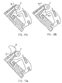
Die Applikationsrolle kann für eine einfachere Ausführungsform auch nicht schwenkbar, also nur drehbar oder überhaupt starr mit den Lippen 33.1 und 33.2 verbunden sein sein, wie in Figur 10 dargestellt. Sie fungiert dadurch in der erfindungsgemässen Weise als Mittel zur Verteilung des Fluids auf der Haut, zum lokalen Zurückschieben der Haut, unmittelbar bevor die Schneiden darüber fahren, und zum teilweisen, allerdings nicht veränderbaren Abdecken des Zuführkanales 31.For a simpler embodiment, the application roller can also not be pivoted, that is to say it can only be rotatably or rigidly connected to the lips 33.1 and 33.2, as shown in FIG. 10 . As a result, it functions in the manner according to the invention as a means for distributing the fluid on the skin, for pushing back the skin locally immediately before the cutting edges pass over it, and for partially but not changeably covering the
An Stelle einer schwenkbaren Applikationsrolle kann auch ein verschiebbar oder federnd gelagerter Klingenträger 34 mit integrierter, drehbar gelagerter oder starrer Applikationsrolle 3 verwendet werden, wie dies in Figur 11 dargestellt ist. Hier ist der Vorteil im konstanten Abstand zwischen Applikationsrolle 3 und Klinge oder Klingen 2 zu sehen. Sind die Klingen federnd gelagert, hat man ausserdem den Vorteil eines konstanten Anpressdruckes auf der Haut, was die Schnittgefahr vermindert. Im unbelasteten Zustand wird der Zuführkanal 31 durch die Federkraft geschlossen, was der Ausführungsform mit dem variablen Zuführspalt entsprechen würde.Instead of a pivotable application roller, a displaceably or resiliently mounted
Die in den Figuren 12 a und b dargestellte Variante besitzt eine manuell verschiebbare äussere Lippe 36.3, mit deren Hilfe die Fluidzufuhr manuell geöffnet, geschlossen und reguliert werden kann. Die Austrittsöffnung ist dadurch zwar nicht selbstregulierend, jedoch kann der Oeffnungsmoment unabhängig vom Pumpendruck bestimmt werden.The variant shown in FIGS. 12 a and b has a manually displaceable outer lip 36.3, with the aid of which the fluid supply can be opened, closed and regulated manually. Although the outlet opening is not self-regulating, the opening torque can be determined independently of the pump pressure.
Bei allen Ausführungsformen kann der Unterteil des Applikationskopfes als Kamm ausgebildet sein, sodass durch eine kämmende Wirkung die Haare schön ausgerichtet der Klinge angeboten werden. Eine entsprechende, beispielhafte Ausführungsform mit einem Kamm 35, der an der äusseren Lippe 33.2 angebracht ist, ist in der Figur 13 dargestellt.In all embodiments, the lower part of the application head can be designed as a comb, so that the hair is offered to the blade in a nicely aligned manner due to a combing effect. A corresponding exemplary embodiment with a comb 35 which is attached to the outer lip 33.2 is shown in FIG. 13
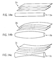
Der Rasierkopf kann je nach Verwendung für das Rasieren von mehr oder weniger ebenen oder mehr gerundeten Flächen entsprechend ausgestaltet werden, indem entsprechend geformte Applikationsrollen oder Applikationsspachtel und Applikationsöffnungen und entsprechend zur Funktion der Rollenform ausgestaltete Klingen zum Einsatz kommen. Die Figuren 14a bis c sind Beispiele dargestellt, bei denen der Verlauf der Schneidklingen im wesentlichen dem Verlauf der Applikationsrolle folgt (wobei sinngemäss solche Formen auch auf die Applikationsspachtel übertragbar sind). Es können auch Abweichungen dieser Verlaufsform sinnvoll sein, aber die Form der Applikationsrolle soll zum Klingenverlauf in einem funktionellen Bezug stehen. Die hier skizzierten Möglichkeiten stellen nur Anregungen zur Weitergestaltung dar und deshalb sind hier lediglich nur eine Applikationsrolle 3 und Klingen 2 in ihrer relativen Anordnung abgebildet. Figur 14a stellt eine typische Anordnung mit zylindrischer Applikationsrolle 3a für das Rasieren von Hautoberflächen dar, die sich von der Applikationsrolle zu einer ebenen Fläche verformen lassen, Figur 14b stellt eine Anordnung mit konvexer Applikationsrolle 3b für das Rasieren von konkaven Flächen wie Vertiefungen, bspw. in den Achselhöhlen, die mit der linearen Klinge nicht mehr erreichbar sind, dar, und Figur 14c stellt eine Anordnung mit einer konkaven Applikationsrolle 3c für das Rasieren von konvexen Flächen wie Erhöhungen, bspw. auf dem Kehlkopf, bei der die lineare Klinge eine erhöhte Verletzungsgefahr mit sich bringen würde, dar. Gemäss den schon gezeigten Ausführungsformen (und gemäss der Prinzipdarstellung in den Figuren 1. bis 1.3) wird der Applikationsspalt der Applikationsrolle auch formlich zugeordnet, wobei auch hier der funktionelle Zusammenhang zwischen Zuführung des Fluids und dessen Verteilung derselbe bleibt. Mit solcherart gestalteten Ausführungsformen kann auf stärker gerundeten Rasierflächen gearbeitet werden.Depending on the use, the shaving head can be designed accordingly for shaving more or less flat or more rounded surfaces by using appropriately shaped application rollers or application spatulas and application openings and blades designed according to the function of the roller shape. FIGS. 14a to c show examples in which the course of the cutting blades essentially follows the course of the application roller (whereby such shapes can also be transferred to the application spatula). Deviations from this shape can also make sense, but the shape of the application roll should be functionally related to the blade shape. The options outlined here only represent suggestions for further development and therefore only one
Claims (19)
- Apparatus for flat or contour shaving with simultaneous application of a thin film of a shaving-specific preparation, comprising a cutting or blade part, an applicator part and a feed part all functionally matching, comprising means for passing a fluid dischargeable under pressure from the feed part into a fluid channel (10) in the applicator part and whereas the applicator part has a slot-like application opening with boundary means (30.1 and 30.2), characterised in that the boundary means (30.1 and 30.2) on the one hand comprise an application roll (3) positioned against the cutting edges (2) and essentially parallel thereto on a rigid inner lip (33.1) and on the other hand comprise a rigid outer lip (33.2) remote from the cutting edges and also essentially parallel thereto, by means of which the fluid is distributed over the skin on moving the apparatus in the cutting direction.
- Apparatus for flat or contour shaving according to claim 1, characterized in that the applicator part for applying and distributing a fluid and the cutting part with blades (2) form a shaver or razor head (1), which can be engaged on the feed part and connects the fluid channel (10) of the feed part to the application opening in the applicator part.
- Apparatus for flat or contour shaving according to claim 1, characterized in that the application roll (3) is mounted in rotary or pivotable manner.
- Apparatus for flat or contour shaving according to claim 3, characterized in that the application roll (3) is placed in rotary and pivotable manner on the inner lip (33.1).
- Apparatus for flat or contour shaving according to claim 3 or 4, characterized in that the pivot pin of the application roll (3) is positioned in such a way and parallel to the slot (A) between the roll (3) and the lip (33.1) that the slot (A) has a minimum width in each pivoting position of the roll (3).
- Applicator according to one of the claims 4 or 5, characterized in that the width of the slot (C) resulting from the pivoting of the roll (3) from the inoperative position into the application position between the lip (33.2) and the roll (3) corresponds to the preparation outlet quantity desired for application.
- Apparatus for flat or contour shaving according to claim 2, characterized in that the application roll (3) is placed in rotary or non-rotary manner on the blade holder (34) and that the blade holder (34) is applied with the aid of resilient means to the razor head.
- Apparatus for flat or contour shaving according to one of the claims 1 to 7, characterized in that the application roll (3 or 3') has a cylindrical, convex or concave application surface.
- Apparatus for flat or contour shaving according to one of the claims 1 to 8, characterized in that a combing means (37) is fitted to the outer boundary means (30.1) parallel to the blades (2).
- Apparatus for flat or contour shaving according to one of the claims 1 to 9, characterized in that the feed part comprises a preparation reservoir (6) and a miniature pump (5) and that together the preparation reservoir (6) and miniature pump (5) form the apparatus handle (4).
- Apparatus for flat or contour shaving according to claim 10, characterized in that the miniature pump (5) comprises an elastic bellows (41) and two one-way valves (42, 43).
- Apparatus for flat or contour shaving according to claim 11, characterized in that diaphragm, ball or piston-type valves are used as one-way valves in the feed part.
- Apparatus for flat or contour shaving according to claim 11, characterized in that the one-way valves of the feed part are formed by opening systems (93/94 or 96/97/98) in the cylindrical pump body (44), whose outlets at the cylinder surface are preferably sealed by O-rings (95 or 99).
- Apparatus for flat or contour shaving according to one of the claims 10 to 13, characterized in that the reservoir part (4.1), pump body (44) and connection part (4.3) form a fixed, assembled part and that the bellows (41) is placed round the pump body (44) and fixed by elastic fastening means (46).
- Apparatus for flat or contour shaving according to claim 14, characterized in that the elastic fastening means (46) are clamping rings.
- Apparatus for flat or contour shaving according to one of the claims 11 to 13, characterized in that the reservoir part (4.1), pump body (44) and connection part (4.3) comprise elastically deformable connection points (K) with the aid of which they are joined together and that the bellows (41) is so constructed that it seals said connection points.
- Apparatus for flat or contour shaving according to one of the claims 11 to 13, characterized in that the reservoir part (4.1), pump body (44) and connection part (43) are held together and sealed against one another by the bellows (41) and that the diaphragm valves (42 or 43) comprise resilient diaphragms located between the reservoir part (4.1) and pump body (44) or between the pump body (44) and the connection part (4.3).
- Apparatus for flat or contour shaving according to one of the claims 10 to 17, characterized in that the preparation reservoir (6) in the feed part comprises a hollow cylinder and a piston (48) movable in the latter.
- Apparatus for flat or contour shaving according to one of the claims 10 to 17, characterized in that the preparation reservoir (6) in the feed part comprises a deformable hollow body.
Applications Claiming Priority (2)
| Application Number | Priority Date | Filing Date | Title |
|---|---|---|---|
| CH2097/90 | 1990-06-22 | ||
| CH209790 | 1990-06-22 |
Publications (2)
| Publication Number | Publication Date |
|---|---|
| EP0463992A1 EP0463992A1 (en) | 1992-01-02 |
| EP0463992B1 true EP0463992B1 (en) | 1994-03-16 |
Family
ID=4225814
Family Applications (1)
| Application Number | Title | Priority Date | Filing Date |
|---|---|---|---|
| EP91810461A Expired - Lifetime EP0463992B1 (en) | 1990-06-22 | 1991-06-17 | Safety razor |
Country Status (7)
| Country | Link |
|---|---|
| US (1) | US5168628A (en) |
| EP (1) | EP0463992B1 (en) |
| JP (1) | JPH04231909A (en) |
| AT (1) | ATE102861T1 (en) |
| DE (1) | DE59101190D1 (en) |
| DK (1) | DK0463992T3 (en) |
| ES (1) | ES2053309T3 (en) |
Cited By (1)
| Publication number | Priority date | Publication date | Assignee | Title |
|---|---|---|---|---|
| DE102008009082A1 (en) * | 2008-02-14 | 2009-08-20 | Peiniger Gmbh | Device and cutting tool for ablative skin treatment |
Families Citing this family (96)
| Publication number | Priority date | Publication date | Assignee | Title |
|---|---|---|---|---|
| ATE103526T1 (en) * | 1991-01-17 | 1994-04-15 | Kai Ind Co Ltd | REPLACEMENT CARTRIDGE FOR SHAVER WITH APPLICATOR. |
| GB2282773A (en) * | 1993-10-13 | 1995-04-19 | Giles Norman Lantos | Safety-razor |
| DE9407891U1 (en) * | 1994-05-16 | 1995-09-14 | Bramlage Gmbh | lipstick |
| US5402574A (en) * | 1994-05-20 | 1995-04-04 | Milner; Joshua P. | Shaving apparatus |
| US5903979A (en) * | 1994-07-13 | 1999-05-18 | The Gillette Company | Safety razors |
| US5678316A (en) * | 1995-12-15 | 1997-10-21 | Warner-Lambert Company | Disposable razor |
| JPH11514562A (en) * | 1996-08-29 | 1999-12-14 | フィリップス エレクトロニクス ネムローゼ フェン ノートシャップ | Hair removal system, hair removal device and cartridge therefor |
| GB2342884A (en) * | 1998-10-23 | 2000-04-26 | Anita Casali | Razor with self-contained lubricant |
| DE19907224C2 (en) * | 1999-02-19 | 2001-02-22 | Braun Gmbh | Liquid container |
| DE19907025A1 (en) | 1999-02-19 | 2000-08-31 | Braun Gmbh | Hair removal device |
| US6167625B1 (en) | 1999-05-18 | 2001-01-02 | Warner-Lambert Company | Shaving implement |
| EP1304196B1 (en) * | 2001-10-22 | 2005-03-09 | Eveready Battery Company, Inc. | Shaving device |
| EP1474272B1 (en) * | 2002-02-13 | 2008-11-26 | Matsushita Electric Works, Ltd. | Hair removing device with a lotion applicator |
| US6763590B2 (en) | 2002-10-21 | 2004-07-20 | Eveready Battery Company, Inc. | Razor assembly having a clutch controlled shaving aid delivery system |
| US6986207B2 (en) * | 2003-01-24 | 2006-01-17 | Ali Saban Selek | Single-use disposable shaving set |
| PL1615751T3 (en) * | 2003-04-07 | 2012-01-31 | Eveready Battery Inc | Shaving aid dispenser system for use in a wet shaving razor |
| AU2003252664A1 (en) * | 2003-04-30 | 2004-11-23 | Eisho Hujibe | Shaving supporting liquid delivery device |
| JP4599047B2 (en) * | 2003-09-30 | 2010-12-15 | 株式会社貝印刃物開発センター | razor |
| US6964097B2 (en) | 2003-12-04 | 2005-11-15 | Eveready Battery Company, Inc. | Shaving apparatus |
| US7043841B2 (en) * | 2003-12-04 | 2006-05-16 | Eveready Battery Co., Inc. | Shaving apparatus |
| US6925716B2 (en) | 2003-12-04 | 2005-08-09 | Eveready Battery Company, Inc. | Shaving apparatus |
| US7121754B2 (en) * | 2003-12-08 | 2006-10-17 | Eveready Battery Company, Inc. | Shaving apparatus with pivot-actuated valve for delivery of shaving aid material |
| US6886254B1 (en) | 2003-12-16 | 2005-05-03 | Eveready Battery Company, Inc. | Shaving apparatus |
| US6910274B1 (en) * | 2003-12-16 | 2005-06-28 | Eveready Battery Company, Inc. | Shaving apparatus |
| US20050138814A1 (en) * | 2003-12-30 | 2005-06-30 | Eveready Battery Company, Inc. | Shaving apparatus with shaving aid material dispenser |
| US7137203B2 (en) * | 2003-12-30 | 2006-11-21 | Eveready Battery Company, Inc. | Shaving apparatus |
| US7997454B2 (en) * | 2007-04-26 | 2011-08-16 | Sealed Air Corporation (Us) | Metering dispensing system with improved valving to prevent accidental dispensing of liquid therefrom |
| US8061566B2 (en) * | 2007-04-26 | 2011-11-22 | Sealed Air Corporation (Us) | Metering dispensing system with improved valving to prevent accidental dispensing of liquid therefrom |
| US7419322B2 (en) * | 2004-03-10 | 2008-09-02 | Poly-D Llc | Fluid dispensing device with metered delivery |
| US7140115B2 (en) * | 2004-05-10 | 2006-11-28 | Greene Todd M | Shaving apparatus with wheel |
| US20060080837A1 (en) * | 2004-10-20 | 2006-04-20 | Robert Johnson | Shaving razors and cartridges |
| DE102004059517A1 (en) * | 2004-12-10 | 2006-06-14 | Mahran Wanli | Razor comprises a handle having a hollow chamber arranged in its middle region for releasing a blade |
| JP2010512291A (en) * | 2006-12-11 | 2010-04-22 | ポリィ−ディー・エルエルシー | Vertical pouch |
| US20080181714A1 (en) * | 2006-12-11 | 2008-07-31 | Poly-D, Llc | Sponge device with urethane and cellulose material combination construction |
| WO2008100754A1 (en) * | 2007-02-09 | 2008-08-21 | Poly-D, Llc | Metered dosing container with independently deformable internal bladder |
| US8128303B2 (en) * | 2007-02-09 | 2012-03-06 | Sealed Air Corporation (Us) | Metering dispensing flexible pouch with spray nozzle |
| CA2678192C (en) * | 2007-02-13 | 2013-10-15 | Poly-D, Llc | Container having a secondary reservoir for metered dosing of additives |
| US20080205970A1 (en) * | 2007-02-23 | 2008-08-28 | Poly-D, Llc | Toothbrush with integrated toothpaste delivery |
| US20080203114A1 (en) * | 2007-02-23 | 2008-08-28 | Poly-D, Llc | Fluid dispenser with docking station |
| WO2008103803A1 (en) * | 2007-02-23 | 2008-08-28 | Poly-D, Llc | Surface cleaner with removable wand |
| WO2008103890A2 (en) * | 2007-02-23 | 2008-08-28 | Poly-D, Llc | Dual chambered fluid dispenser with mixing chamber |
| WO2008103896A2 (en) * | 2007-02-23 | 2008-08-28 | Poly-D, Llc | Surface scrubber with rotating pad |
| ES2396966T3 (en) * | 2007-03-14 | 2013-03-01 | Sealed Air Corporation (Us) | Dispenser with double pump system |
| US8292120B2 (en) * | 2007-03-26 | 2012-10-23 | Sealed Air Corporation (Us) | Hanging liquid dispenser |
| WO2008134776A1 (en) * | 2007-04-26 | 2008-11-06 | John Christopher De Klerk | Razor |
| AU2008263479B2 (en) * | 2007-06-12 | 2013-11-28 | The Gillette Company Llc | Manually actuable liquid dispensing razor |
| CL2008001727A1 (en) * | 2007-06-12 | 2010-02-05 | Gillette Co | Razor comprising a handle with a proximal and a distal end, an adapter neck pivotally attached to the proximal end of the handle, a pump attached to a feeder channel, a cartridge connection fork, and a shaver cartridge. to shave. |
| FR2924044B1 (en) * | 2007-11-28 | 2010-05-28 | Lindal France | MANUAL RAZOR WITH SWIVEL SHAVING HEAD |
| WO2009094222A1 (en) * | 2008-01-23 | 2009-07-30 | Poly-D, Llc | Razor with integrated dispensing of shaving treatments |
| US20090320293A1 (en) * | 2008-03-19 | 2009-12-31 | Sean Peter Clarke | Manually Actuable Liquid Dispensing Razor With Degradable Shaving Aid |
| US20090263176A1 (en) * | 2008-04-21 | 2009-10-22 | Mileti Robert J | Replaceable Cartridge Dispenser Assembly |
| US9744680B2 (en) | 2008-10-17 | 2017-08-29 | The Gillette Company | Fluid dispensing hair removal device |
| AU2009305732B2 (en) * | 2008-10-17 | 2014-10-23 | The Gillette Company Llc | Fluid dispensing hair removal device |
| EP2218437A1 (en) * | 2009-02-17 | 2010-08-18 | The Gillette Company | Shaving compositions comprising dye-loaded particles |
| US8745877B2 (en) * | 2009-03-23 | 2014-06-10 | The Gillette Company | Manually actuable liquid dispensing razor |
| US8826543B2 (en) * | 2009-03-23 | 2014-09-09 | The Gillette Company | Manually actuable liquid dispensing razor |
| EP2451587B1 (en) | 2009-07-08 | 2020-02-19 | InnovationCooperative3D, LLC | Metering dispensing system with one-piece pump assembly |
| JP5701899B2 (en) * | 2009-12-15 | 2015-04-15 | コーニンクレッカ フィリップス エヌ ヴェ | Shaving device |
| CA2793461A1 (en) * | 2010-03-15 | 2011-09-22 | The Gillette Company | Hair removal device |
| WO2011115981A1 (en) * | 2010-03-15 | 2011-09-22 | The Gillette Company | Liquid dispensing device comprising a peristaltic pump |
| AU2011240573A1 (en) * | 2010-04-15 | 2012-11-08 | The Gillette Company | Fluid dispensing hair removal device |
| US8720072B2 (en) | 2010-08-11 | 2014-05-13 | Thomas J. Bucco | Razor with three-axis multi-position capability |
| MX2013004696A (en) * | 2010-10-27 | 2013-06-12 | Gillette Co | Composition dispensing device comprising a non-foaming hydrating composition. |
| CN102452092B (en) | 2010-10-28 | 2015-04-01 | 吉列公司 | Hair removing device for dispensing liquid |
| CN102452085B (en) * | 2010-10-28 | 2016-01-27 | 吉列公司 | For the pump of the hair removal device of dispense liquid |
| CN102452088B (en) * | 2010-10-28 | 2015-07-01 | 吉列公司 | Hair removing device with blade holder holding covering part |
| CN102452095B (en) * | 2010-10-28 | 2014-10-29 | 吉列公司 | Applicator of hair removing device for distributing liquid |
| CN103189169B (en) * | 2010-10-28 | 2015-09-09 | 吉列公司 | There is the application device of the deflector for hair removal device |
| CN102452096A (en) * | 2010-10-28 | 2012-05-16 | 吉列公司 | Handle part of hair removing device used for distributing liquid |
| CN102452091B (en) * | 2010-10-28 | 2015-08-12 | 吉列公司 | For the application device with deflector of hair removal device |
| CN102452094A (en) | 2010-10-28 | 2012-05-16 | 吉列公司 | Hair removing kit for distributing liquid |
| WO2012058214A1 (en) * | 2010-10-28 | 2012-05-03 | The Gillette Company | Applicator with a baffle for a hair removal device |
| EP2974627B1 (en) * | 2010-12-13 | 2018-06-20 | Novis AG | Apparatus for extracting juice and pulp from fruit or vegetables |
| JP5860707B2 (en) * | 2011-05-18 | 2016-02-16 | 株式会社貝印刃物開発センター | Swing razor |
| US9156175B2 (en) * | 2011-12-09 | 2015-10-13 | The Gillette Company | Fluid applicator for a personal-care appliance |
| WO2013082815A1 (en) * | 2011-12-09 | 2013-06-13 | The Gillette Company | Fluid dispensing shaving razor |
| US9283685B2 (en) * | 2012-07-26 | 2016-03-15 | Shavelogic, Inc. | Pivoting razors |
| US9486930B2 (en) | 2012-09-27 | 2016-11-08 | Shavelogic, Inc. | Shaving systems |
| WO2014051842A1 (en) | 2012-09-27 | 2014-04-03 | Shavelogic, Inc. | Shaving systems |
| WO2014051843A1 (en) | 2012-09-28 | 2014-04-03 | Shavelogic, Inc. | Shaving systems |
| US9623575B2 (en) | 2012-12-18 | 2017-04-18 | Shavelogic, Inc. | Shaving systems |
| US20150158192A1 (en) | 2013-12-09 | 2015-06-11 | Shavelogic, Inc. | Multi-material pivot return for shaving systems |
| US11325270B2 (en) | 2014-03-21 | 2022-05-10 | Sl Ip Company Llc | Metal spring return and method |
| EP3546156B1 (en) | 2018-03-30 | 2021-03-10 | The Gillette Company LLC | Razor handle with a pivoting portion |
| JP7090727B2 (en) | 2018-03-30 | 2022-06-24 | ザ ジレット カンパニー リミテッド ライアビリティ カンパニー | Razor handle with pivot part |
| USD874061S1 (en) | 2018-03-30 | 2020-01-28 | The Gillette Company Llc | Shaving razor cartridge |
| EP3774223A1 (en) | 2018-03-30 | 2021-02-17 | The Gillette Company LLC | Shaving razor cartridge |
| EP3774230A1 (en) | 2018-03-30 | 2021-02-17 | The Gillette Company LLC | Razor handle with a pivoting portion |
| WO2019190961A1 (en) | 2018-03-30 | 2019-10-03 | The Gillette Company Llc | Razor handle with a pivoting portion |
| US11607820B2 (en) | 2018-03-30 | 2023-03-21 | The Gillette Company Llc | Razor handle with movable members |
| EP3774227A1 (en) | 2018-03-30 | 2021-02-17 | The Gillette Company LLC | Razor handle with movable members |
| BR112020020132A2 (en) | 2018-03-30 | 2021-01-05 | The Gillette Company Llc | HANDLE OF SHAVING OR DEVILING APPLIANCE WITH MOBILE LIMBS |
| CN111819044B (en) | 2018-03-30 | 2022-09-16 | 吉列有限责任公司 | Razor handle with pivoting portion |
| EP3658342B1 (en) * | 2018-07-08 | 2022-03-23 | Youti Kuo | Shaving applicator device |
| US10864647B2 (en) * | 2019-01-22 | 2020-12-15 | Reyna Alvarez | Adjustable razor and method of use |
| KR102289030B1 (en) * | 2019-09-11 | 2021-08-11 | 주식회사 도루코 | Razor Cartridge and Razor Assembly using the Same |
Family Cites Families (17)
| Publication number | Priority date | Publication date | Assignee | Title |
|---|---|---|---|---|
| US1892836A (en) * | 1932-04-29 | 1933-01-03 | George R Harvey | Combination razor and shaving brush |
| GB490808A (en) * | 1937-02-17 | 1938-08-17 | Manuel Andres Y Gonzalez | Improvements in or relating to razors, particularly safety razors |
| GB488143A (en) * | 1937-09-18 | 1938-07-01 | Arthur James Wakeford | Improvements in or relating to safety razors |
| CH279398A (en) * | 1947-10-29 | 1951-11-30 | Noel Davies James | Razor with shaving liquid. |
| US2861338A (en) * | 1955-09-20 | 1958-11-25 | Edward R Boland | Lather-applying safety razors |
| US2866265A (en) * | 1956-11-02 | 1958-12-30 | John D Kells | Combination safety razor and lather dispenser having telescopically related head and dispensing assemblies |
| GB879736A (en) * | 1959-01-20 | 1961-10-11 | Baruch Shalev | Improvements in safety razors |
| US3139683A (en) * | 1963-04-02 | 1964-07-07 | Waldman Joseph | Safety razor with fluid distributing manifold |
| US3417468A (en) * | 1965-07-27 | 1968-12-24 | Miyauchi Hideo | Razor |
| US4074429A (en) * | 1976-08-23 | 1978-02-21 | Roberts Thomas G | Novel lathering device and razor assembly |
| US4023269A (en) * | 1976-08-30 | 1977-05-17 | Lopez Jr Lorenzo | Shaving device |
| US4077119A (en) * | 1977-02-16 | 1978-03-07 | Jose Manuel Sellera | Shaving device |
| US4314404A (en) * | 1980-02-20 | 1982-02-09 | Ruiz Rene A | Razor with pre-wetting or capillarizer system |
| FR2494603A1 (en) * | 1980-11-26 | 1982-05-28 | Normos Norbert | Manually-operated fluid-sprayer - has chamber with elastic wall and rigid tube from nozzle to discharge passage |
| US4562644A (en) * | 1984-08-10 | 1986-01-07 | Hitchens Peter B | Lubricant-applying safety razor |
| FR2605923A1 (en) * | 1986-10-31 | 1988-05-06 | Kolacinski Patrice | Mechanical razor with incorporated shaving product dispenser |
| DE8911246U1 (en) * | 1989-09-21 | 1991-01-24 | Wilkinson Sword Gmbh, 5650 Solingen, De |
-
1991
- 1991-06-17 EP EP91810461A patent/EP0463992B1/en not_active Expired - Lifetime
- 1991-06-17 AT AT91810461T patent/ATE102861T1/en not_active IP Right Cessation
- 1991-06-17 DK DK91810461.3T patent/DK0463992T3/en active
- 1991-06-17 DE DE91810461T patent/DE59101190D1/en not_active Expired - Fee Related
- 1991-06-17 ES ES91810461T patent/ES2053309T3/en not_active Expired - Lifetime
- 1991-06-19 US US07/718,557 patent/US5168628A/en not_active Expired - Fee Related
- 1991-06-21 JP JP3150137A patent/JPH04231909A/en active Pending
Cited By (2)
| Publication number | Priority date | Publication date | Assignee | Title |
|---|---|---|---|---|
| DE102008009082A1 (en) * | 2008-02-14 | 2009-08-20 | Peiniger Gmbh | Device and cutting tool for ablative skin treatment |
| DE102008009082B4 (en) * | 2008-02-14 | 2017-08-31 | Peiniger Gmbh | Device and cutting tool for ablative skin treatment |
Also Published As
| Publication number | Publication date |
|---|---|
| ES2053309T3 (en) | 1994-07-16 |
| JPH04231909A (en) | 1992-08-20 |
| US5168628A (en) | 1992-12-08 |
| ATE102861T1 (en) | 1994-04-15 |
| DK0463992T3 (en) | 1994-04-05 |
| EP0463992A1 (en) | 1992-01-02 |
| DE59101190D1 (en) | 1994-04-21 |
Similar Documents
| Publication | Publication Date | Title |
|---|---|---|
| EP0463992B1 (en) | Safety razor | |
| EP0605397B1 (en) | Razor head, particularly a blade unit | |
| AT395816B (en) | DEVICE FOR MANUAL SKIN MASSAGE AND AT THE SAME TIME APPLYING A LIQUID OR PASTE-LIKE PRODUCT TO THE SKIN | |
| DE3829395C2 (en) | Device for applying a product to a surface, in particular applicator device for a cosmetic, in particular depilatory product | |
| DE2260724C3 (en) | Applicator for a cosmetic preparation housed in a container | |
| DE60206686T2 (en) | Wet shaver with protection / transfer roller and interchangeable shaving aid | |
| EP0013691A1 (en) | Dispenser for pasty products | |
| DE60115183T2 (en) | Pen, in particular for a cream, gel or paste-like product | |
| EP0155616A2 (en) | Container with a device for the application of liquid to a surface | |
| EP1799070B1 (en) | Application device | |
| CH682041A5 (en) | Applicator for thin film cosmetic or pharmaceutical prepn. on skin - has storage device in handgrip with application by means of rotatable and pivotable roller | |
| EP1784096A2 (en) | Applicator | |
| EP2272393A1 (en) | Dye applicator | |
| DE1807236A1 (en) | Mechanical razor | |
| DE3245877A1 (en) | CLEANING CASSETTE | |
| EP2383045B1 (en) | Dispensing device for liquids | |
| DE60025346T2 (en) | BAND DONORS | |
| EP0901839A2 (en) | Device for applying fluids onto a substrate | |
| EP0268860B1 (en) | Device for handling liquids for hair treatment or for a similar use | |
| DE2055159A1 (en) | Pressurized can, in particular spray can | |
| DE2050458C3 (en) | Hand tool for applying liquid material | |
| DE102004048164B3 (en) | Device to apply shaving cream, foam, gel or other conditioner onto the skin, cartridge for same, dry shave razor and epiliery device has grip holding conditioner linked to application piece formed of small strips | |
| DE19963065B4 (en) | Device for applying a hair treatment agent and use of the device | |
| DE2801551C3 (en) | Printing device with an operating lever, a push rod or the like | |
| DE836163C (en) | Device for printing on the top and for moistening or gumming paper strips on the underside |
Legal Events
| Date | Code | Title | Description |
|---|---|---|---|
| PUAI | Public reference made under article 153(3) epc to a published international application that has entered the european phase |
Free format text: ORIGINAL CODE: 0009012 |
|
| AK | Designated contracting states |
Kind code of ref document: A1 Designated state(s): AT BE CH DE DK ES FR GB GR IT LI LU NL SE |
|
| RAP1 | Party data changed (applicant data changed or rights of an application transferred) |
Owner name: KAI INDUSTRIES CO. LTD. |
|
| 17P | Request for examination filed |
Effective date: 19920624 |
|
| 17Q | First examination report despatched |
Effective date: 19921029 |
|
| GRAA | (expected) grant |
Free format text: ORIGINAL CODE: 0009210 |
|
| AK | Designated contracting states |
Kind code of ref document: B1 Designated state(s): AT BE CH DE DK ES FR GB GR IT LI LU NL SE |
|
| REF | Corresponds to: |
Ref document number: 102861 Country of ref document: AT Date of ref document: 19940415 Kind code of ref document: T |
|
| ITF | It: translation for a ep patent filed |
Owner name: JACOBACCI CASETTA & PERANI S.P.A. |
|
| REG | Reference to a national code |
Ref country code: DK Ref legal event code: T3 |
|
| REF | Corresponds to: |
Ref document number: 59101190 Country of ref document: DE Date of ref document: 19940421 |
|
| GBT | Gb: translation of ep patent filed (gb section 77(6)(a)/1977) |
Effective date: 19940413 |
|
| ET | Fr: translation filed | ||
| REG | Reference to a national code |
Ref country code: ES Ref legal event code: FG2A Ref document number: 2053309 Country of ref document: ES Kind code of ref document: T3 |
|
| EPTA | Lu: last paid annual fee | ||
| REG | Reference to a national code |
Ref country code: GR Ref legal event code: FG4A Free format text: 3011937 |
|
| PLBE | No opposition filed within time limit |
Free format text: ORIGINAL CODE: 0009261 |
|
| STAA | Information on the status of an ep patent application or granted ep patent |
Free format text: STATUS: NO OPPOSITION FILED WITHIN TIME LIMIT |
|
| EAL | Se: european patent in force in sweden |
Ref document number: 91810461.3 |
|
| 26N | No opposition filed | ||
| PGFP | Annual fee paid to national office [announced via postgrant information from national office to epo] |
Ref country code: GR Payment date: 19950417 Year of fee payment: 5 |
|
| PGFP | Annual fee paid to national office [announced via postgrant information from national office to epo] |
Ref country code: LU Payment date: 19950501 Year of fee payment: 5 |
|
| PGFP | Annual fee paid to national office [announced via postgrant information from national office to epo] |
Ref country code: BE Payment date: 19950510 Year of fee payment: 5 |
|
| PGFP | Annual fee paid to national office [announced via postgrant information from national office to epo] |
Ref country code: GB Payment date: 19950606 Year of fee payment: 5 |
|
| PGFP | Annual fee paid to national office [announced via postgrant information from national office to epo] |
Ref country code: ES Payment date: 19950615 Year of fee payment: 5 Ref country code: DK Payment date: 19950615 Year of fee payment: 5 |
|
| PGFP | Annual fee paid to national office [announced via postgrant information from national office to epo] |
Ref country code: SE Payment date: 19950616 Year of fee payment: 5 Ref country code: AT Payment date: 19950616 Year of fee payment: 5 |
|
| PGFP | Annual fee paid to national office [announced via postgrant information from national office to epo] |
Ref country code: FR Payment date: 19950628 Year of fee payment: 5 |
|
| PGFP | Annual fee paid to national office [announced via postgrant information from national office to epo] |
Ref country code: NL Payment date: 19950629 Year of fee payment: 5 |
|
| PGFP | Annual fee paid to national office [announced via postgrant information from national office to epo] |
Ref country code: DE Payment date: 19950829 Year of fee payment: 5 |
|
| PG25 | Lapsed in a contracting state [announced via postgrant information from national office to epo] |
Ref country code: LU Free format text: LAPSE BECAUSE OF NON-PAYMENT OF DUE FEES Effective date: 19960617 Ref country code: GB Effective date: 19960617 Ref country code: DK Effective date: 19960617 Ref country code: AT Effective date: 19960617 |
|
| REG | Reference to a national code |
Ref country code: DK Ref legal event code: EBP |
|
| PG25 | Lapsed in a contracting state [announced via postgrant information from national office to epo] |
Ref country code: SE Effective date: 19960618 Ref country code: ES Free format text: LAPSE BECAUSE OF THE APPLICANT RENOUNCES Effective date: 19960618 |
|
| PG25 | Lapsed in a contracting state [announced via postgrant information from national office to epo] |
Ref country code: BE Effective date: 19960630 |
|
| BERE | Be: lapsed |
Owner name: KAI INDUSTRIES CO. LTD Effective date: 19960630 |
|
| PG25 | Lapsed in a contracting state [announced via postgrant information from national office to epo] |
Ref country code: GR Free format text: THE PATENT HAS BEEN ANNULLED BY A DECISION OF A NATIONAL AUTHORITY Effective date: 19961231 |
|
| PG25 | Lapsed in a contracting state [announced via postgrant information from national office to epo] |
Ref country code: NL Effective date: 19970101 |
|
| REG | Reference to a national code |
Ref country code: GR Ref legal event code: MM2A Free format text: 3011937 |
|
| GBPC | Gb: european patent ceased through non-payment of renewal fee |
Effective date: 19960617 |
|
| PG25 | Lapsed in a contracting state [announced via postgrant information from national office to epo] |
Ref country code: FR Effective date: 19970228 |
|
| PG25 | Lapsed in a contracting state [announced via postgrant information from national office to epo] |
Ref country code: DE Effective date: 19970301 |
|
| EUG | Se: european patent has lapsed |
Ref document number: 91810461.3 |
|
| NLV4 | Nl: lapsed or anulled due to non-payment of the annual fee |
Effective date: 19970101 |
|
| REG | Reference to a national code |
Ref country code: FR Ref legal event code: ST |
|
| REG | Reference to a national code |
Ref country code: ES Ref legal event code: FD2A Effective date: 19991007 |
|
| PGFP | Annual fee paid to national office [announced via postgrant information from national office to epo] |
Ref country code: CH Payment date: 20030522 Year of fee payment: 13 |
|
| PG25 | Lapsed in a contracting state [announced via postgrant information from national office to epo] |
Ref country code: LI Free format text: LAPSE BECAUSE OF NON-PAYMENT OF DUE FEES Effective date: 20040630 Ref country code: CH Free format text: LAPSE BECAUSE OF NON-PAYMENT OF DUE FEES Effective date: 20040630 |
|
| REG | Reference to a national code |
Ref country code: CH Ref legal event code: PL |
|
| PG25 | Lapsed in a contracting state [announced via postgrant information from national office to epo] |
Ref country code: IT Free format text: LAPSE BECAUSE OF NON-PAYMENT OF DUE FEES;WARNING: LAPSES OF ITALIAN PATENTS WITH EFFECTIVE DATE BEFORE 2007 MAY HAVE OCCURRED AT ANY TIME BEFORE 2007. THE CORRECT EFFECTIVE DATE MAY BE DIFFERENT FROM THE ONE RECORDED. Effective date: 20050617 |