EP0463819A2 - Optisches Informationsaufzeichnungs-/Wiedergabegerät - Google Patents
Optisches Informationsaufzeichnungs-/Wiedergabegerät Download PDFInfo
- Publication number
- EP0463819A2 EP0463819A2 EP91305632A EP91305632A EP0463819A2 EP 0463819 A2 EP0463819 A2 EP 0463819A2 EP 91305632 A EP91305632 A EP 91305632A EP 91305632 A EP91305632 A EP 91305632A EP 0463819 A2 EP0463819 A2 EP 0463819A2
- Authority
- EP
- European Patent Office
- Prior art keywords
- linear motor
- optical head
- recording
- medium
- motor coil
- Prior art date
- Legal status (The legal status is an assumption and is not a legal conclusion. Google has not performed a legal analysis and makes no representation as to the accuracy of the status listed.)
- Ceased
Links
Images


Classifications
-
- G—PHYSICS
- G11—INFORMATION STORAGE
- G11B—INFORMATION STORAGE BASED ON RELATIVE MOVEMENT BETWEEN RECORD CARRIER AND TRANSDUCER
- G11B7/00—Recording or reproducing by optical means, e.g. recording using a thermal beam of optical radiation by modifying optical properties or the physical structure, reproducing using an optical beam at lower power by sensing optical properties; Record carriers therefor
- G11B7/08—Disposition or mounting of heads or light sources relatively to record carriers
- G11B7/085—Disposition or mounting of heads or light sources relatively to record carriers with provision for moving the light beam into, or out of, its operative position or across tracks, otherwise than during the transducing operation, e.g. for adjustment or preliminary positioning or track change or selection
- G11B7/0857—Arrangements for mechanically moving the whole head
- G11B7/08582—Sled-type positioners
-
- G—PHYSICS
- G11—INFORMATION STORAGE
- G11B—INFORMATION STORAGE BASED ON RELATIVE MOVEMENT BETWEEN RECORD CARRIER AND TRANSDUCER
- G11B7/00—Recording or reproducing by optical means, e.g. recording using a thermal beam of optical radiation by modifying optical properties or the physical structure, reproducing using an optical beam at lower power by sensing optical properties; Record carriers therefor
- G11B7/08—Disposition or mounting of heads or light sources relatively to record carriers
- G11B7/09—Disposition or mounting of heads or light sources relatively to record carriers with provision for moving the light beam or focus plane for the purpose of maintaining alignment of the light beam relative to the record carrier during transducing operation, e.g. to compensate for surface irregularities of the latter or for track following
- G11B7/0925—Electromechanical actuators for lens positioning
- G11B7/093—Electromechanical actuators for lens positioning for focusing and tracking
Definitions
- This invention relates to an optical information recording-reproducing apparatus (hereinafter referred to as the optical disk apparatus) for effecting the recording and/or reproduction of information on a recording medium by the use of an optical head, and particularly to the structure of the optical head.
- the optical disk apparatus for effecting the recording and/or reproduction of information on a recording medium by the use of an optical head, and particularly to the structure of the optical head.
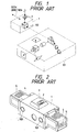
- An optical head in a prior-art optical disk apparatus is constructed as shown, for example, in Figure 1 of the accompanying drawings.
- the reference numeral 101 designates a fixed optical head fixed to an apparatus base for effecting the oscillation of a laser beam and the reproducing process of reflected light
- the reference numeral 1 denotes a movable optical head for condensing and applying the laser beam from the fixed optical head onto a recording medium for the recording and/or reproduction of information and movable in the radial direction of a disk (the direction of arrow indicated in the figure)
- the reference numeral 2 designates an objective lens for condensing the laser beam on the surface of the recording medium
- the reference numeral 102 denotes a bending mirror for bending the laser beam, emitted in parallel to the seek direction of the movable optical head from the fixed optical head, in a direction perpendicular to the surface of the medium.
- Figure 2 of the accompanying drawings shows the details of the movable optical head shown in Figure 1.
- reference numerals identical to those in Figure 1 designate identical portions.
- the reference numeral 3 denotes an actuator for driving the objective lens in the focusing and tracking directions of the recording medium
- the reference numeral 5 designates a linear motor coil cooperating with a permanent magnet and a yoke, not shown (fixed to the apparatus side) to drive the movable optical head
- the reference numeral 103 denotes a bearing for receiving the guide, not shown, of the movable optical head.
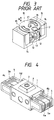
- Figure 3 of the accompanying drawings shows the details of the actuator shown in Figure 2.
- the reference numeral 2 designates the objective lens
- the reference numeral 10 denotes an objective lens holder
- the reference numeral 11 designates a pin fixed to an optical head base
- the reference numeral 12 denotes a tracking coil mounted on the objective lens holder 10
- the reference numeral 13 designates a focusing coil
- the reference numeral 14 denotes a permanent magnet
- the reference numeral 15 designates a yoke.
- the seek operation of the optical head will now be described on the basis of the above-described construction.
- the entire movable optical head is first moved to near a desired position on the recording medium by a linear motor.
- the movable optical head is moved by the linear motor until a desired track falls within the movable range of the actuator in the direction of tracks by the number of transverse tracks and position detecting means such as an encoder.
- the desired track is then finely sought by the actuator, and when the laser spot arrives at the desired track, the laser spot is controlled to follow that track (tracking and focusing control), thus terminating the seek operation.
- the movable optical head of the above-described conventional construction carries thereon a complicated and large tracking and focusing actuator as shown in Figure 3 and therefore, has structural limitations in the realization of its compactness and light weight, and this has led to the problem that the required speedup of the seek operation cannot be achieved.
- the present invention has been made in view of the above-noted problem and the object thereof is to provide a movable optical head of novel construction which can realize the speedup of the seek operation as compared with the prior art apparatus.
- an optical information recording-reproducing apparatus for optically effecting the recording and/or reproduction of information on a disk-like recording medium which has an optical head for applying a light beam for effecting the recording and/or reproduction of said information to a desired track on said medium, a guide for guiding said optical head radially of said medium to have access to the desired track on said medium, a yoke and a permanent magnet fixed to said apparatus to generate a driving force for moving said optical head along said guide, a first linear motor coil for the rough driving and a second linear motor coil for the precise driving provided on said optical head.
- Figure 4 shows an embodiment of the movable optical head of the present invention.
- the reference numeral 1 designates a movable optical head body
- the reference numeral 2 denotes an objective lens for condensing a laser beam on the surface of a recording medium
- the reference numeral 3 designates an actuator for driving the objective lens only in a focus direction
- the reference numeral 4 denotes a bobbin mounted on the movable optical head body 1
- the reference characters 5a and 5b designate linear motor coils for the rough driving of the movable optical head which are connected together and wound around the bobbin
- the reference characters 6a, 6b, 6c and 6d denote linear motor coils for the precise driving of the movable optical head which are connected together and wound around the bobbin.
- the linear motor coils for the rough driving are wound about the central portion of the outer periphery of the bobbin and the linear motor coils for the precise seek are wound on the opposite end portions of the outer periphery of the bobbin so as to surround the linear motor coils for the rough driving, thereby adjusting the weight balance of the entire optical head.
- the linear motor coils for the rough driving need be of a high output specification for generating a high thrust in order to shorten the seek time. Therefore, these coils are small in resistance value and great in the number of turns, but are great in inductance.
- the linear motor coils for the precise driving give priority to quick responsiveness than to thrust because the tracking operation heretofore effected by an actuator is effected by a linear motor. Therefore, the linear motor coils for the precise driving are set so as to be great in resistance and small in the number of turns (greater in resistance and smaller in the number of turns than at least the linear motor coils for the rough driving) and small in inductance (smaller in inductance than at least the linear motor coils for the rough driving).
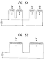
- Figures 5A and 5B show methods of connecting the linear motor coils shown in Figure 4.
- Figure 5A shows a method of connecting the linear motor coils for the precise driving
- Figure 5B shows a method of connecting the linear motor coils for the rough driving.
- R represents the resistance values of the coils
- T represents the numbers of turns of the coils.
- the inductance L increases in proportion to an increase in the number of turns of the coil. Also, since the thrust of the linear motor is proportional to the electric current x the number of turns, the rising characteristics of the two coils are as shown in Figure 6.
- Figure 6 (a) shows the rising characteristic of the linear motor coils for the precise driving, and (b) shows the rising characteristic of the linear motor coils for the rough driving.
- the final thrust is 1/4 of that of the linear motor coils for the rough driving, but the former coils are quick in the rising of the thrust and excellent in rapid responsiveness.
- Figure 9 shows a construction in which the optical head shown in Figure 4 is incorporated into a guide mechanism on the apparatus side.
- the same reference numerals as those in Figure 4 designate the same members.
- the reference numeral 7 denotes a magnet
- the reference numeral 8 designate yokes
- the reference numeral 9 denotes guide rails for guiding the movable optical head radially of the medium
- the reference numeral 25 designates a base fed fixed to the apparatus side for supporting them.
- the linear motor coils of the optical head are electrically energized, the linear motor coils 5 or 6 cooperate with the magnet 7 and yokes 8 to generate a driving force in the direction of arrow and the optical head are moved along the guide rails 9.
- the reference numeral 16 denotes a disk-like recording medium (hereinafter referred to as the disk)
- the reference numeral 17 designates a spindle motor for rotating the disk
- the reference numeral 18 denotes a spindle motor control circuit for controlling the spindle motor 17
- the reference numeral 19 designates a focusing servo for controlling the driving of the objective lens 2 in the focusing direction on the basis of a focusing error signal detected by the fixed optical head 101
- the reference numeral 20 denotes a tracking servo for effecting the tracking control of the movable optical head 1 in the tracking direction on the basis of a tracking signal detected by the fixed optical head 101
- the reference numeral 21 designates a rough driving driver for controlling the rough driving of the movable optical head 1 in the radial direction of the disk
- the reference numeral 22 denote
- the CPU 24 controls the switch 23 so that the light beam spot may follow the desired track, and brings the rough driving driver 21 and the linear motor coils 5 for the rough driving into their non-connected state, and newly brings only the tracking servo 20 and linear motor coils 6 for the precise driving into their connected state. Then, the precise driving of the movable optical head, i.e., tracking control, is effected on the basis of a tracking error signal detected by the fixed optical head 101.
- the CPU 24 controls the switch 23 to bring only the precise driving driver and linear motor coils 6 for the precise driving into their connected state.
- the CPU 24 starts the movement of the movable optical head in accordance with the speed profile, and when the light beam spot arrives at the desired track, the CPU 24 controls the switch 23 to bring only the tracking servo 20 and linear motor coils 6 for the precise driving into their connected state, and effects the tracking control of the movable optical head so that the light beam spot may follow the desired track.
- the rough driving and precise driving of the light beam spot can be accomplished by only the linear motors and the operation of the objective lens actuator in the tracking direction becomes unnecessary and therefore, as shown in Figures 7 and 8, the objective lens actuator can be made compact and light in weight and further, the entire optical head can be made compact and light in weight.
Landscapes
- Moving Of The Head For Recording And Reproducing By Optical Means (AREA)
- Moving Of Heads (AREA)
- Optical Recording Or Reproduction (AREA)
Applications Claiming Priority (2)
| Application Number | Priority Date | Filing Date | Title |
|---|---|---|---|
| JP167645/90 | 1990-06-25 | ||
| JP2167645A JPH0460929A (ja) | 1990-06-25 | 1990-06-25 | 光学ヘッド及び該光学ヘッドを備えた光学的情報記録再生装置 |
Publications (2)
| Publication Number | Publication Date |
|---|---|
| EP0463819A2 true EP0463819A2 (de) | 1992-01-02 |
| EP0463819A3 EP0463819A3 (en) | 1992-07-08 |
Family
ID=15853608
Family Applications (1)
| Application Number | Title | Priority Date | Filing Date |
|---|---|---|---|
| EP19910305632 Ceased EP0463819A3 (en) | 1990-06-25 | 1991-06-21 | Optical information recording reproducing apparatus |
Country Status (3)
| Country | Link |
|---|---|
| US (1) | US5548568A (de) |
| EP (1) | EP0463819A3 (de) |
| JP (1) | JPH0460929A (de) |
Cited By (1)
| Publication number | Priority date | Publication date | Assignee | Title |
|---|---|---|---|---|
| EP0553664A2 (de) * | 1992-01-30 | 1993-08-04 | Hitachi, Ltd. | Gerät für optische Platten |
Families Citing this family (1)
| Publication number | Priority date | Publication date | Assignee | Title |
|---|---|---|---|---|
| US7061712B2 (en) * | 2004-11-17 | 2006-06-13 | International Business Machines Corporation | Mono pole piece for a two stage tape drive actuator |
Citations (3)
| Publication number | Priority date | Publication date | Assignee | Title |
|---|---|---|---|---|
| EP0149888A1 (de) * | 1983-12-23 | 1985-07-31 | Magnetic Peripherals Inc. | Servosystem für ein Datenaufzeichnungssystem und ein zugehöriges Datenaufzeichnungssystem |
| EP0350225A2 (de) * | 1988-07-07 | 1990-01-10 | Oki Electric Industry Company, Limited | Anordnung für einen optischen Kopf |
| EP0405604A2 (de) * | 1989-06-30 | 1991-01-02 | Fuji Xerox Co., Ltd. | Magnetooptisches Aufzeichnungs-/Wiedergabegerät |
Family Cites Families (13)
| Publication number | Priority date | Publication date | Assignee | Title |
|---|---|---|---|---|
| JPS57103131A (en) * | 1980-12-18 | 1982-06-26 | Sony Corp | Biaxial driver |
| JPS6226676A (ja) * | 1985-07-27 | 1987-02-04 | Mitsubishi Electric Corp | デイスク装置のキヤリツジ支持装置 |
| JPS63257927A (ja) * | 1987-04-15 | 1988-10-25 | Pioneer Electronic Corp | ピツクアツプアクチユエ−タ |
| JPH0199486A (ja) * | 1987-10-12 | 1989-04-18 | Pioneer Electron Corp | ピックアップ駆動用リニアモータの制御装置 |
| EP0346479B1 (de) * | 1987-10-28 | 1994-01-05 | Oki Electric Industry Company, Limited | Optischer kopf |
| EP0325434B1 (de) * | 1988-01-19 | 1994-10-12 | Fujitsu Limited | Spurzugangsregelsystem |
| US5101398A (en) * | 1988-02-19 | 1992-03-31 | Canon Kabushiki Kaisha | Device for magnetically guiding movement of a moving body such as an optical head |
| JPH01287875A (ja) * | 1988-05-13 | 1989-11-20 | Toshiba Corp | 情報処理装置 |
| JPH0756695B2 (ja) * | 1988-09-02 | 1995-06-14 | 松下電器産業株式会社 | ヘッド移送装置 |
| JP2785290B2 (ja) * | 1988-12-19 | 1998-08-13 | ソニー株式会社 | 光ディスクのシーク及びトラッキング装置 |
| US5150343A (en) * | 1989-07-19 | 1992-09-22 | Matsushita Electric Industrial Co., Ltd. | Miniaturized low-power-consumption optical head provided with a state transformation mechanism |
| JPH03203032A (ja) * | 1989-12-28 | 1991-09-04 | Toshiba Corp | 光学系移動装置 |
| JP2723646B2 (ja) * | 1990-03-27 | 1998-03-09 | キヤノン株式会社 | 光学的情報処理装置 |
-
1990
- 1990-06-25 JP JP2167645A patent/JPH0460929A/ja active Pending
-
1991
- 1991-06-21 EP EP19910305632 patent/EP0463819A3/en not_active Ceased
-
1995
- 1995-02-23 US US08/393,021 patent/US5548568A/en not_active Expired - Fee Related
Patent Citations (3)
| Publication number | Priority date | Publication date | Assignee | Title |
|---|---|---|---|---|
| EP0149888A1 (de) * | 1983-12-23 | 1985-07-31 | Magnetic Peripherals Inc. | Servosystem für ein Datenaufzeichnungssystem und ein zugehöriges Datenaufzeichnungssystem |
| EP0350225A2 (de) * | 1988-07-07 | 1990-01-10 | Oki Electric Industry Company, Limited | Anordnung für einen optischen Kopf |
| EP0405604A2 (de) * | 1989-06-30 | 1991-01-02 | Fuji Xerox Co., Ltd. | Magnetooptisches Aufzeichnungs-/Wiedergabegerät |
Cited By (3)
| Publication number | Priority date | Publication date | Assignee | Title |
|---|---|---|---|---|
| EP0553664A2 (de) * | 1992-01-30 | 1993-08-04 | Hitachi, Ltd. | Gerät für optische Platten |
| EP0553664A3 (en) * | 1992-01-30 | 1995-03-08 | Hitachi Ltd | Optical disk apparatus |
| US5453972A (en) * | 1992-01-30 | 1995-09-26 | Hitachi, Ltd. | Optical disk apparatus |
Also Published As
| Publication number | Publication date |
|---|---|
| US5548568A (en) | 1996-08-20 |
| JPH0460929A (ja) | 1992-02-26 |
| EP0463819A3 (en) | 1992-07-08 |
Similar Documents
| Publication | Publication Date | Title |
|---|---|---|
| US4942562A (en) | Pickup actuator for disk-type media | |
| US6944103B2 (en) | Optical pick-up actuator | |
| US5187702A (en) | Apparatus for moving an optical system | |
| US4596448A (en) | Optical system support and positioning device for use in an optical reading apparatus | |
| US4822139A (en) | Optical head apparatus for optical disc player | |
| US4958335A (en) | Optical head assembly with a minimum of inertia and feasible for high high-speed access | |
| EP0367094A2 (de) | Optischer Plattenspieler | |
| JPS583142A (ja) | 光学式情報処理装置 | |
| EP1450356B1 (de) | Kippbewegungsaktuator für einen optischen Lesekopf und ein diesen Aktuator verwendendes optisches Aufzeichnungs- und/oder Wiedergabegerät | |
| US5581524A (en) | Magnetooptical information recording and/or reproducing method and apparatus in which prior to actual recording and/or reproducing, information is recorded on a recording medium to set reference conditions for actual recording and/or reproducing | |
| US5548568A (en) | Optical-information-recording apparatus having fine and rough driving control | |
| JPS6220903Y2 (de) | ||
| WO2003088220A1 (en) | Read/write head for optical disk drive and optical disk drive comprising such a read/write head | |
| US5212673A (en) | Compact optical disk drive unit | |
| US5272688A (en) | Apparatus for writing and/or reading information on and/or from optical card | |
| JP2739049B2 (ja) | 光学式ディスク装置 | |
| EP0427302B1 (de) | Aufzeichnungsvorrichtung für eine optische Matrizenplatte | |
| US5450386A (en) | Optical disk device including a support member for movably supporting an objective lens in focusing and radial directions with respect to an optical disk | |
| JPH08203105A (ja) | 対物レンズ駆動装置 | |
| JPH0765383A (ja) | 光記録再生装置 | |
| JPH09147371A (ja) | 光学ディスク装置 | |
| JPH11185266A (ja) | 2軸アクチュエータ、光学ピックアップ及び光ディスク装置 | |
| JPH04123322A (ja) | 光記録再生装置におけるレンズアクチュエータの制御方法 | |
| JPH06274914A (ja) | 光情報記録再生装置 | |
| JPH11259881A (ja) | 光ディスク装置 |
Legal Events
| Date | Code | Title | Description |
|---|---|---|---|
| PUAI | Public reference made under article 153(3) epc to a published international application that has entered the european phase |
Free format text: ORIGINAL CODE: 0009012 |
|
| AK | Designated contracting states |
Kind code of ref document: A2 Designated state(s): DE FR GB IT NL |
|
| PUAL | Search report despatched |
Free format text: ORIGINAL CODE: 0009013 |
|
| AK | Designated contracting states |
Kind code of ref document: A3 Designated state(s): DE FR GB IT NL |
|
| 17P | Request for examination filed |
Effective date: 19921125 |
|
| 17Q | First examination report despatched |
Effective date: 19941006 |
|
| STAA | Information on the status of an ep patent application or granted ep patent |
Free format text: STATUS: THE APPLICATION HAS BEEN REFUSED |
|
| 18R | Application refused |
Effective date: 19960413 |