EP0462771A2 - Casting mould - Google Patents
Casting mould Download PDFInfo
- Publication number
- EP0462771A2 EP0462771A2 EP91305445A EP91305445A EP0462771A2 EP 0462771 A2 EP0462771 A2 EP 0462771A2 EP 91305445 A EP91305445 A EP 91305445A EP 91305445 A EP91305445 A EP 91305445A EP 0462771 A2 EP0462771 A2 EP 0462771A2
- Authority
- EP
- European Patent Office
- Prior art keywords
- edge surface
- casting mould
- edge
- bolt
- attached
- Prior art date
- Legal status (The legal status is an assumption and is not a legal conclusion. Google has not performed a legal analysis and makes no representation as to the accuracy of the status listed.)
- Withdrawn
Links
Images


Classifications
-
- B—PERFORMING OPERATIONS; TRANSPORTING
- B28—WORKING CEMENT, CLAY, OR STONE
- B28B—SHAPING CLAY OR OTHER CERAMIC COMPOSITIONS; SHAPING SLAG; SHAPING MIXTURES CONTAINING CEMENTITIOUS MATERIAL, e.g. PLASTER
- B28B7/00—Moulds; Cores; Mandrels
- B28B7/0002—Auxiliary parts or elements of the mould
- B28B7/0014—Fastening means for mould parts, e.g. for attaching mould walls on mould tables; Mould clamps
- B28B7/0017—Fastening means for mould parts, e.g. for attaching mould walls on mould tables; Mould clamps for attaching mould walls on mould tables
-
- B—PERFORMING OPERATIONS; TRANSPORTING
- B28—WORKING CEMENT, CLAY, OR STONE
- B28B—SHAPING CLAY OR OTHER CERAMIC COMPOSITIONS; SHAPING SLAG; SHAPING MIXTURES CONTAINING CEMENTITIOUS MATERIAL, e.g. PLASTER
- B28B7/00—Moulds; Cores; Mandrels
- B28B7/0002—Auxiliary parts or elements of the mould
- B28B7/0014—Fastening means for mould parts, e.g. for attaching mould walls on mould tables; Mould clamps
- B28B7/002—Fastening means for mould parts, e.g. for attaching mould walls on mould tables; Mould clamps using magnets
-
- B—PERFORMING OPERATIONS; TRANSPORTING
- B28—WORKING CEMENT, CLAY, OR STONE
- B28B—SHAPING CLAY OR OTHER CERAMIC COMPOSITIONS; SHAPING SLAG; SHAPING MIXTURES CONTAINING CEMENTITIOUS MATERIAL, e.g. PLASTER
- B28B7/00—Moulds; Cores; Mandrels
- B28B7/0029—Moulds or moulding surfaces not covered by B28B7/0058 - B28B7/36 and B28B7/40 - B28B7/465, e.g. moulds assembled from several parts
- B28B7/0035—Moulds characterised by the way in which the sidewalls of the mould and the moulded article move with respect to each other during demoulding
- B28B7/0041—Moulds characterised by the way in which the sidewalls of the mould and the moulded article move with respect to each other during demoulding the sidewalls of the mould being moved only parallelly away from the sidewalls of the moulded article
-
- B—PERFORMING OPERATIONS; TRANSPORTING
- B28—WORKING CEMENT, CLAY, OR STONE
- B28B—SHAPING CLAY OR OTHER CERAMIC COMPOSITIONS; SHAPING SLAG; SHAPING MIXTURES CONTAINING CEMENTITIOUS MATERIAL, e.g. PLASTER
- B28B7/00—Moulds; Cores; Mandrels
- B28B7/02—Moulds with adjustable parts specially for modifying at will the dimensions or form of the moulded article
Definitions
- This invention relates to a casting mould for casting concrete elements, in which mould there is a bottom surface, two edge surfaces and two end surfaces, whereby at least one edge surface can be moved and placed a desired distance from the other edge surface.
- a tipping mould equipped with edges is normally used as flush mould.
- a casting machine drives over a casting table and portions sealing compound in the mould. Under the table there are jogging devices for packing the sealing compound. After the concrete has hardened, the table is tipped around a pivoted axle along one edge almost to a vertical position, the mould edge thus raised, i.e. the upper edge, is removed and the element is lifted off the table by links in its sides.
- the position of the upper edge has to be able to be changed to suit the size of the element to be cast.
- the installation of a loose edge at a desired location is realized by keys or screws. Moving arid installing the edge in this manner requires a lot of handmade carpentry.
- An objective of this invention is to create a casting mould, the upper edge of which is easy to move and install at a desired location.
- Characteristic of the casting mould according to the invention is that the movable edge surface is equipped with transfer elements connected to driving gear by transfer mechanism for transferring the edge surface.
- the movable upper edge is in the preferable embodiment of the invention equipped with bolts, which can be electrically magnetized, whereby the magnetic bolt is installed in its support so that it can be turned or slid to cause the bolt to be transferred towards the bottom surface and away from the bottom surface.
- the flush mould according to the invention there is a smooth steel surface 1 as base, ends 2, upper edge 3, which gets higher when turning the mould, and bottom edge 4, which gets lower.
- the ends 2 and the bottom edge 4 can be turned in a manner known per se when needed by an articulated arm 5 away from the cast element (position shown by dash line in Fig. 2).
- the upper edge 3 can be moved so that its distance from the bottom edge can be adjusted (arrow A).
- the transfer is carried out by a transfer mechanism installed in the ends of the edge 3.
- a transfer mechanism installed in the ends of the edge 3.
- Both chains run around their own chain gear 7 and pulley.
- Chain gears 7 are located at the ends of a differential axle 8 extending over the whole length of the mould.
- the differential axle is driven by a driving motor 9 equipped with gears controlling the motor is carried out by operating panel 10.
- a transfer element 11 in which is mounted in bearings a supporting roll 12 which runs along a stock rail 13 in the end of the mold.
- the arm 14 of the transfer element 11 extends through an opening 15 beneath the end 2 and its end is connected to an end of the upper edge 3.
- the upper edge 3 is equipped with magnetic bolts 30, the structure of which will he described later.
- a compressed-air hose needed for the mechanism for loosening the bolts is identified by a reference number 38.
- a compressed-air supply lead 39 is attached in a folding pipe, whereby the articulated pipe settles in its position, when the edge 3 and the hose 38 is moved.
- Fig. 4-7 there is shown another embodiment of the invention. It can be used for longer moulds, because more than two transfer elements in the ends can be used for moving the upper edge.
- screw jacks 17 are used as the transfer mechanism. These are located beneath the base level 1 and attached to the outer surface of the upper edge 3 by connecting rods 18. Screws of the screw jacks 17 are rotated by drive gears 20 and cogged belts 21 attached to the differential axle 19 (Fig. 6). The differential axle 19 is rotated by the drive motor 22 and a cog belt 23. When rotated, the screws 17 screw into or out of guide bars 24 equipped with inside threads. The guide bars are supported slidingly on the bottom surface 1 of the table by sliding sleeves 25.
- the connecting rod 18 has one end connected to the outer end of the guide bar 24 by a link 26.
- the other end of the connecting rod 18 is connected to a double T-rail 28 attached to the upper edge 3 by three supporting rolls 27.
- the supporting rolls 27 can roll along the longitudinal direction of the mould along a flange of the double T-rail 28.
- Fig. 4 and 6 there is also a tipping link 29, around which the base level 1 can be inclined in a manner known per se, so that the upper edge 3 is lifted upwards.
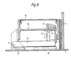
- the movable upper edge 3 can be locked in both embodiments described above in its position by the magnetic bolts 30 shown in Fig. 8.
- magnets as bolts is known per se and they are well adapted for locking against a smooth steel surface 1. The following describes a new solution for fastening and loosening the bolts.
- a swinging crank arm 32 In the supporting double T-rail 28 in the upper edge there is attached a swinging crank arm 32 through a link 31. In the outer edge of the crank arm 32 there is attached an electromagnet 30. Also in the crank arm 32 there is attached a draw hook 33, which extends upwards through an opening 34 in the double T-rail 28. The upper edge of the draw hook rests on the hose 35. In the side of the mould there are several bolts located a certain distance from each other. The hose extends in the longitudinal direction of the mould under all the draw hooks of the bolts over the double T-rail 28. A cover lid 36 covers the bolts.
- the bolt When the electromagnet is magnetized by electric current, the bolt rests against the table surface 1 supported by a bearing surface and the magnet. Then compressed air is lead to the hose 35 in order to create clamping pressure (approx. 2 bar). The hose then distends and its upper surface presses against the bottom surface of the draw hook 33 directing true holding force of the magnet to the upper surface of the double T-rail and thus the bolt presses the edge plate 3 against the table surface 1.
- the edge plate 3 When the edge plate 3 needs to be removed, the electric current is disconnected from the magnets 30. Magnetization does not, however, immediately discharge from the bolts.
- a higher loosening pressure e. g. 6 bar
- the hose then pushes the draw hook 33 upwards with a force which is higher than the total force of the magnet, and the magnet 30 comes loose.
- the invention is not limited only to the embodiments described above, but it can vary in different ways
- the transfer movement of the upper edge can be-created not only by chains or screws, but also by e.g. a hydraulic cylinder-piston- device.
- the hose 35 can be pressurized not only by gas but also by hydraulic fluid.
- other expandable elements e.g. separate pneumatic cushions or pneumatic cylinders can be used.
- Between the hook 33 and the rail 28 can also be located an eccentric rotatable around a horizontal axle, with which eccentric the distance between the hook and the rail can be changed.
- a controlled lifting and lowering of the hook 33 can also be carried out by e.g. running rails.
Landscapes
- Engineering & Computer Science (AREA)
- Manufacturing & Machinery (AREA)
- Chemical & Material Sciences (AREA)
- Ceramic Engineering (AREA)
- Mechanical Engineering (AREA)
- Moulds, Cores, Or Mandrels (AREA)
- On-Site Construction Work That Accompanies The Preparation And Application Of Concrete (AREA)
- Devices For Post-Treatments, Processing, Supply, Discharge, And Other Processes (AREA)
- Manufacturing Of Tubular Articles Or Embedded Moulded Articles (AREA)
Abstract
Description
- This invention relates to a casting mould for casting concrete elements, in which mould there is a bottom surface, two edge surfaces and two end surfaces, whereby at least one edge surface can be moved and placed a desired distance from the other edge surface.
- When casting wall elements of concrete a tipping mould equipped with edges is normally used as flush mould. A casting machine drives over a casting table and portions sealing compound in the mould. Under the table there are jogging devices for packing the sealing compound. After the concrete has hardened, the table is tipped around a pivoted axle along one edge almost to a vertical position, the mould edge thus raised, i.e. the upper edge, is removed and the element is lifted off the table by links in its sides.
- The position of the upper edge has to be able to be changed to suit the size of the element to be cast. The installation of a loose edge at a desired location is realized by keys or screws. Moving arid installing the edge in this manner requires a lot of handmade carpentry.
- An objective of this invention is to create a casting mould, the upper edge of which is easy to move and install at a desired location. Characteristic of the casting mould according to the invention is that the movable edge surface is equipped with transfer elements connected to driving gear by transfer mechanism for transferring the edge surface. The movable upper edge is in the preferable embodiment of the invention equipped with bolts, which can be electrically magnetized, whereby the magnetic bolt is installed in its support so that it can be turned or slid to cause the bolt to be transferred towards the bottom surface and away from the bottom surface. On the upper side of the support of the movable edge surface, beneath a drawing element attached to the magnetic bolt, there is an intermediate element, with which the distance between the support of the movable edge surface and the drawing element can be changed.
- Installation of the mechanically movable upper edge does not require handwork at all. Edge distance from the opposite edge can be adjusted totally steplessly. The magnetic bolts enable easy and quick installation of the edge, and, when the magnetic bolts are fastened in a manner described above, also loosening of the bolts off the table surface is quick and easy to carry out.
- The invention and its details will be described in more detail in the following referring to the accompanying drawings, in which:-
- Fig. 1 is a top view of a casting mold according to the invention,
- Fig. 2 is a longitudinal section of an end of the mould shown in Fig. 1 in enlarged scale,
- Fig. 3 is a top view of a part of the end shown in Fig. 2,
- Fig. 4 is a top view of a further casting mould according to the invention,
- Fig. 5 is a cross profile B-B of the upper edge of the mould shown in Fig. 4 in enlarged scale,
- Fig. 6 is a cross profile of the bottom edge of the mould shown in Fig. 4, without side plate,
- Fig. 7 is a top view of a part of Fig. 4 in enlarged scale, and
- Fig. 8 is a cross profile of a bolt used in the upper edge of the mould according to the invention.
- In the flush mould according to the invention there is a
smooth steel surface 1 as base,ends 2,upper edge 3, which gets higher when turning the mould, and bottom edge 4, which gets lower. Theends 2 and the bottom edge 4 can be turned in a manner known per se when needed by an articulatedarm 5 away from the cast element (position shown by dash line in Fig. 2). - The
upper edge 3 can be moved so that its distance from the bottom edge can be adjusted (arrow A). In the embodiment shown in Fig. 1-3 the transfer is carried out by a transfer mechanism installed in the ends of theedge 3. In both ends of the mould, beneath thebase surface 1, there is anendless chain 6 extending across the mould. Both chains run around their own chain gear 7 and pulley. Chain gears 7 are located at the ends of adifferential axle 8 extending over the whole length of the mould. The differential axle is driven by a drivingmotor 9 equipped with gears controlling the motor is carried out byoperating panel 10. - To both
endless chains 6 there is attached atransfer element 11, in which is mounted in bearings a supportingroll 12 which runs along astock rail 13 in the end of the mold. Thearm 14 of thetransfer element 11 extends through anopening 15 beneath theend 2 and its end is connected to an end of theupper edge 3. - When rotating
differential axle 8 with themotor 9, thechains 6 move thetransfer elements 11 in synchronism and theupper edge 3 moves correspondingly either towards the bottom edge 4 or away from it. Before starting the casting aplywood strip 16 is attached to bothends 2, the length of which strip corresponds to the width of the element to be cast. The strip covers the opening 15. Then the upper edge is moved to its position by the transfer mechanism. - The
upper edge 3 is equipped withmagnetic bolts 30, the structure of which will he described later. A compressed-air hose needed for the mechanism for loosening the bolts is identified by areference number 38. A compressed-air supply lead 39 is attached in a folding pipe, whereby the articulated pipe settles in its position, when theedge 3 and thehose 38 is moved. - In Fig. 4-7 there is shown another embodiment of the invention. It can be used for longer moulds, because more than two transfer elements in the ends can be used for moving the upper edge.
- In a long mould,
screw jacks 17 are used as the transfer mechanism. These are located beneath thebase level 1 and attached to the outer surface of theupper edge 3 by connectingrods 18. Screws of thescrew jacks 17 are rotated bydrive gears 20 and coggedbelts 21 attached to the differential axle 19 (Fig. 6). Thedifferential axle 19 is rotated by thedrive motor 22 and acog belt 23. When rotated, thescrews 17 screw into or out ofguide bars 24 equipped with inside threads. The guide bars are supported slidingly on thebottom surface 1 of the table by slidingsleeves 25. - The connecting
rod 18 has one end connected to the outer end of theguide bar 24 by alink 26. The other end of the connectingrod 18 is connected to a double T-rail 28 attached to theupper edge 3 by three supportingrolls 27. The supportingrolls 27 can roll along the longitudinal direction of the mould along a flange of the double T-rail 28. - When moving the
edge 3 the connectingrods 18 are kept parallel to thescrews 17, whereby they direct push or pull force against the edge. After the edge has been locked in its position, the connectingrods 18 projecting sidewards can be directed away. This is carried out by abalance rope 40 and apneumatic cylinder 41. Asupport 42 of the supportingrolls 27 is attached to thebalance rope 40 running through two pulleys in the longitudinal direction of the table. The ends of the rope are fastened to the arms of the pneumatic cylinder containing two pistons. With the cylinder the rope and the supports 42 along with it can be moved in the longitudinal direction of the table. When moving thesupport 42 sidewards, the guide bar of the screw jacks is simultaneously pulled under the table, whereby the connecting rod folds into a position shown by the dash line in Fig. 7. - In Fig. 4 and 6 there is also a tipping
link 29, around which thebase level 1 can be inclined in a manner known per se, so that theupper edge 3 is lifted upwards. - In the casting mould according to the invention the movable
upper edge 3 can be locked in both embodiments described above in its position by themagnetic bolts 30 shown in Fig. 8. Using magnets as bolts is known per se and they are well adapted for locking against asmooth steel surface 1. The following describes a new solution for fastening and loosening the bolts. - In the supporting double T-
rail 28 in the upper edge there is attached a swingingcrank arm 32 through alink 31. In the outer edge of thecrank arm 32 there is attached anelectromagnet 30. Also in thecrank arm 32 there is attached adraw hook 33, which extends upwards through anopening 34 in the double T-rail 28. The upper edge of the draw hook rests on thehose 35. In the side of the mould there are several bolts located a certain distance from each other. The hose extends in the longitudinal direction of the mould under all the draw hooks of the bolts over the double T-rail 28. Acover lid 36 covers the bolts. - When the electromagnet is magnetized by electric current, the bolt rests against the
table surface 1 supported by a bearing surface and the magnet. Then compressed air is lead to thehose 35 in order to create clamping pressure (approx. 2 bar). The hose then distends and its upper surface presses against the bottom surface of thedraw hook 33 directing true holding force of the magnet to the upper surface of the double T-rail and thus the bolt presses theedge plate 3 against thetable surface 1. - When the
edge plate 3 needs to be removed, the electric current is disconnected from themagnets 30. Magnetization does not, however, immediately discharge from the bolts. In order to loosen the magnets of the table 1, a higher loosening pressure (e. g. 6 bar) is lead to thehose 35. The hose then pushes thedraw hook 33 upwards with a force which is higher than the total force of the magnet, and themagnet 30 comes loose. - The invention is not limited only to the embodiments described above, but it can vary in different ways The transfer movement of the upper edge can be-created not only by chains or screws, but also by e.g. a hydraulic cylinder-piston- device.
- In the magnet the
hose 35 can be pressurized not only by gas but also by hydraulic fluid. Instead of the hose, other expandable elements e.g. separate pneumatic cushions or pneumatic cylinders can be used. Between thehook 33 and therail 28 can also be located an eccentric rotatable around a horizontal axle, with which eccentric the distance between the hook and the rail can be changed. Instead of theturnable arm 32, a controlled lifting and lowering of thehook 33 can also be carried out by e.g. running rails.
Claims (10)
- Casting mould for casting concrete elements, in which mould there is a bottom surface (1), two edge surfaces (3, 4) and two end surfaces (2), whereby at least one edge surface (3) can be moved and installed a desired distance from the other edge surface (4), characterized in that the movable edge surface (3) is equipped with transfer elements (11; 18) connected to a driving gear (9; 23) by a transfer mechanism (8, 6; 17, 24) in order to move the edge surface.
- Casting mould as in claim 1, characterized in that the transfer element (11) is attached to the end of the movable edge surface (3) by an element (14) extending through an opening (15) between the end surface (2) and the bottom surface (1).
- Casting mould as in claim 1 or 2, characterized in that the transfer mechanism (17, 24) located beneath the bottom surface (1) is connected to the movable edge (3) by a transfer element (18) attached to the outer side of the edge (3).
- Casting mould as in one of the claims 1-3, characterized in that two or more transfer mechanisms (6, 17) are connected to the driving gear (9) with a mutual driving axle (8, 19).
- Casting mould as in one of the claims 1-4, characterized in that the movable edge surface (3) is equipped with electrically magnetizable bolts (30) in order to lock the edge surface to the bottom surface (1), the bolt (30) is attached to its support so that the bolt can be moved towards the bottom surface (1) and away from the bottom surface, and over the support (28) of the movable edge surface (3), beneath the draw element (33) attached to the magnetic bolt (30), there is located a connecting element (35), with which the distance between the support (28) of the edge surface (3) and the draw element (33) can be changed.
- Casting mould as in claim 5, characterized in that the connecting element (35) is an element which is expandable hydraulically.
- Casting mould as in claim 6, characterized in that the connecting element (35) is a rubber hose, which goes under the draw elements (33) connected to several magnetic bolts (30).
- Casting mould as in claim 6 or 7, characterized in that the connecting element (35) is expandable so that its height corresponds to the distance between the bottom surface of the draw element (33) and the support (28) of the movable edge surface (3), when the magnetic bolt and the movable edge surface (3) rest against the bottom surface (1).
- Casting mould as in claim 8, characterized in that the connecting element (35) is expandable so that the draw element (33) and the magnetic bolt (30) along with it rise up from the bottom surface (1), when the movable edge surface (3) rests against the bottom surface (1).
- Casting mould for casting concrete elements, in which a movable edge surface (3) is equipped with electrically magnetizable bolts (30) in order to lock the edge surface to the bottom surface (1), characterized in that the bolt (30) is attached to its support so that the bolt can be moved towards the bottom surface (1) and away from the bottom surface, and over the support (28) of the movable edge surface (3), beneath the draw element (33) attached to the magnetic bolt (30), there is located a connecting element (35), with which the distance between the support (28) of the edge surface (3) and the draw element (33) can be changed.
Applications Claiming Priority (2)
| Application Number | Priority Date | Filing Date | Title |
|---|---|---|---|
| FI903061 | 1990-06-18 | ||
| FI903061A FI88472C (en) | 1990-06-18 | 1990-06-18 | casting mold |
Publications (2)
| Publication Number | Publication Date |
|---|---|
| EP0462771A2 true EP0462771A2 (en) | 1991-12-27 |
| EP0462771A3 EP0462771A3 (en) | 1992-03-04 |
Family
ID=8530655
Family Applications (1)
| Application Number | Title | Priority Date | Filing Date |
|---|---|---|---|
| EP19910305445 Withdrawn EP0462771A3 (en) | 1990-06-18 | 1991-06-17 | Casting mould |
Country Status (8)
| Country | Link |
|---|---|
| US (1) | US5277396A (en) |
| EP (1) | EP0462771A3 (en) |
| JP (1) | JPH0584729A (en) |
| KR (1) | KR920000448A (en) |
| CA (1) | CA2044752A1 (en) |
| FI (1) | FI88472C (en) |
| MY (1) | MY129993A (en) |
| RU (1) | RU2053114C1 (en) |
Cited By (4)
| Publication number | Priority date | Publication date | Assignee | Title |
|---|---|---|---|---|
| EP0945238A2 (en) * | 1998-03-27 | 1999-09-29 | Addtek Research & Development Oy Ab | A removal side wall system for a casting mould |
| EP0945237A2 (en) * | 1998-03-27 | 1999-09-29 | Addtek Research & Development Oy Ab | A removal side wall system for a casting mould |
| EP1900489A2 (en) | 2006-09-13 | 2008-03-19 | Elematic Oy Ab | Sidewall construction of a casting mold |
| FR3016138A1 (en) * | 2014-01-07 | 2015-07-10 | Sateco Sa | PREFABRICATING MOLD OF A BUILDING ELEMENT COMPRISING SYNCHRONIZED CONTROL MEANS |
Families Citing this family (8)
| Publication number | Priority date | Publication date | Assignee | Title |
|---|---|---|---|---|
| US6021995A (en) * | 1997-05-30 | 2000-02-08 | Dec International, Inc. | Adjustable mold for a molded food processing system |
| US6244579B1 (en) * | 2000-02-02 | 2001-06-12 | Enidine, Incorporated | Light press manufactured (LPM) wire rope isolator and method of manufacture |
| DE20309970U1 (en) * | 2003-06-27 | 2004-11-04 | Bt Baubedarf Magdeburg Gmbh | holder |
| FI20050583A (en) * | 2005-06-01 | 2006-12-02 | Elematic Oy Ab | Edge system for casting mold |
| FI125405B (en) * | 2008-04-29 | 2015-09-30 | Elematic Oyj | Side construction of casting mold |
| FI20105685A (en) * | 2010-06-15 | 2011-12-16 | Elematic Group Oy | Edge mold unit and edge unit removal unit |
| CN105984025A (en) * | 2015-02-09 | 2016-10-05 | 任丘市永基建筑安装工程有限公司 | Assembled mold pulley controlled traveling technology |
| CN114800789B (en) * | 2022-03-29 | 2023-12-26 | 浙江捷城建筑科技有限公司 | PC component mould fixer |
Citations (9)
| Publication number | Priority date | Publication date | Assignee | Title |
|---|---|---|---|---|
| US1571763A (en) * | 1925-06-02 | 1926-02-02 | Samuel R Edmonds | Dimension stone and sill machine |
| US1677480A (en) * | 1928-07-17 | Concrete-block machine | ||
| US3195207A (en) * | 1962-10-15 | 1965-07-20 | Coignet Construct Edmond | Moulding device for all materials, concrete, reinforced concrete, plastic products, ceramics and the like |
| DE1813094A1 (en) * | 1968-12-06 | 1970-06-25 | Seidner Maschf E | Formwork for the production of precast concrete elements |
| DE2023531A1 (en) * | 1969-05-16 | 1970-11-19 | Davy and United Engineering Company Ltd., Sheffield (Großbritannien) | Mold for concrete pouring devices |
| DE2241316A1 (en) * | 1972-08-23 | 1974-03-07 | Wfg Westd Fertigteilwerk Gruen | SWITCH-ON DEVICE |
| SU937154A1 (en) * | 1980-12-01 | 1982-06-23 | Киевский Филиал Конструкторско-Технологического Бюро По Промышленности Строительной Индустрии /Ктб "Стройиндустрия"/ Министерства Промышленного Строительства Ссср "Главстройиндустрия" | Form for producing concrete mixture products |
| FR2552145A1 (en) * | 1983-09-15 | 1985-03-22 | Quille Entreprise | Device for retaining a casting stop or wall-pocket element on a metal shuttering element |
| DE3905305A1 (en) * | 1988-02-26 | 1989-09-07 | Betongindustri Ab | Closure for mould frames |
Family Cites Families (14)
| Publication number | Priority date | Publication date | Assignee | Title |
|---|---|---|---|---|
| US1323345A (en) * | 1919-12-02 | wisner | ||
| US1516710A (en) * | 1923-07-18 | 1924-11-25 | Caputo Louis | Concrete-block-molding machine |
| US3071833A (en) * | 1960-03-21 | 1963-01-08 | Fmc Corp | Molding apparatus |
| US3530540A (en) * | 1968-03-01 | 1970-09-29 | Ralph C Mueller | Molding device |
| GB1319082A (en) * | 1970-06-08 | 1973-05-31 | Nat Res Dev | Concrete pressing processes and apparatus |
| DE2042151A1 (en) * | 1970-08-25 | 1972-03-02 | Nat Res Dev | Edge shaping device |
| FR2163897A5 (en) * | 1971-12-06 | 1973-07-27 | Coignet Edmond Const | |
| SU476991A1 (en) * | 1972-03-20 | 1975-07-15 | Центральный научно-исследовательский и проектный институт типового и экспериментального проектирования жилища | Device for magnetic fastening the sides to the pallet of the form in the manufacture of concrete products |
| US3924295A (en) * | 1974-01-09 | 1975-12-09 | David L Verburg | Apparatus for freeze forming meat products |
| SU700334A2 (en) * | 1978-06-14 | 1979-11-30 | Киевский Филиал Конструкторско-Технологического Бюро "Стройиндустрия" | Extensible insert-board for manufacturing reinforced-concrete articles |
| DE2907508A1 (en) * | 1979-02-26 | 1980-09-04 | Magnetfab Bonn Gmbh | Loose formwork magnetic attachment system - has slot one end of magnet with eccentrically mounted swinging detaching lever |
| DE3176328D1 (en) * | 1980-04-02 | 1987-08-27 | Sergio Sartorio | A method and a former for the manufacture of building elements and elements thus obtained |
| FR2510027A1 (en) * | 1981-07-24 | 1983-01-28 | Sodeteg | DEVICE FOR HANDLING RULES FOR MANUFACTURING MOLDS OR FORMWORKS OF CONCRETE OR CONCRETE PANELS |
| JPH0118336Y2 (en) * | 1984-10-18 | 1989-05-29 |
-
1990
- 1990-06-18 FI FI903061A patent/FI88472C/en not_active IP Right Cessation
-
1991
- 1991-06-04 MY MYPI91000981A patent/MY129993A/en unknown
- 1991-06-14 KR KR1019910009885A patent/KR920000448A/en not_active Application Discontinuation
- 1991-06-14 JP JP3169383A patent/JPH0584729A/en active Pending
- 1991-06-17 CA CA002044752A patent/CA2044752A1/en not_active Abandoned
- 1991-06-17 RU SU914895754A patent/RU2053114C1/en active
- 1991-06-17 EP EP19910305445 patent/EP0462771A3/en not_active Withdrawn
- 1991-06-18 US US07/717,256 patent/US5277396A/en not_active Expired - Fee Related
Patent Citations (9)
| Publication number | Priority date | Publication date | Assignee | Title |
|---|---|---|---|---|
| US1677480A (en) * | 1928-07-17 | Concrete-block machine | ||
| US1571763A (en) * | 1925-06-02 | 1926-02-02 | Samuel R Edmonds | Dimension stone and sill machine |
| US3195207A (en) * | 1962-10-15 | 1965-07-20 | Coignet Construct Edmond | Moulding device for all materials, concrete, reinforced concrete, plastic products, ceramics and the like |
| DE1813094A1 (en) * | 1968-12-06 | 1970-06-25 | Seidner Maschf E | Formwork for the production of precast concrete elements |
| DE2023531A1 (en) * | 1969-05-16 | 1970-11-19 | Davy and United Engineering Company Ltd., Sheffield (Großbritannien) | Mold for concrete pouring devices |
| DE2241316A1 (en) * | 1972-08-23 | 1974-03-07 | Wfg Westd Fertigteilwerk Gruen | SWITCH-ON DEVICE |
| SU937154A1 (en) * | 1980-12-01 | 1982-06-23 | Киевский Филиал Конструкторско-Технологического Бюро По Промышленности Строительной Индустрии /Ктб "Стройиндустрия"/ Министерства Промышленного Строительства Ссср "Главстройиндустрия" | Form for producing concrete mixture products |
| FR2552145A1 (en) * | 1983-09-15 | 1985-03-22 | Quille Entreprise | Device for retaining a casting stop or wall-pocket element on a metal shuttering element |
| DE3905305A1 (en) * | 1988-02-26 | 1989-09-07 | Betongindustri Ab | Closure for mould frames |
Non-Patent Citations (1)
| Title |
|---|
| SOVIET INVENTIONS ILLUSTRATED , DERWENT PUBLICATIONS LTD. , WEEK K17 , ABSTRACT NØ F7200 K/17 , JUNE 6 ,1983 & SU-A-937154 (KIEV CONS IND TECH) JUNE 28 ,1982 * |
Cited By (8)
| Publication number | Priority date | Publication date | Assignee | Title |
|---|---|---|---|---|
| EP0945238A2 (en) * | 1998-03-27 | 1999-09-29 | Addtek Research & Development Oy Ab | A removal side wall system for a casting mould |
| EP0945237A2 (en) * | 1998-03-27 | 1999-09-29 | Addtek Research & Development Oy Ab | A removal side wall system for a casting mould |
| EP0945238A3 (en) * | 1998-03-27 | 2001-11-14 | Addtek Research & Development Oy Ab | A removal side wall system for a casting mould |
| EP0945237A3 (en) * | 1998-03-27 | 2001-11-14 | Addtek Research & Development Oy Ab | A removal side wall system for a casting mould |
| EP1900489A2 (en) | 2006-09-13 | 2008-03-19 | Elematic Oy Ab | Sidewall construction of a casting mold |
| EP1900489A3 (en) * | 2006-09-13 | 2010-10-06 | Elematic Oy Ab | Sidewall construction of a casting mold |
| US7931250B2 (en) | 2006-09-13 | 2011-04-26 | Elematic Oy Ab | Sidewall construction of a casting mold |
| FR3016138A1 (en) * | 2014-01-07 | 2015-07-10 | Sateco Sa | PREFABRICATING MOLD OF A BUILDING ELEMENT COMPRISING SYNCHRONIZED CONTROL MEANS |
Also Published As
| Publication number | Publication date |
|---|---|
| FI88472C (en) | 1993-05-25 |
| KR920000448A (en) | 1992-01-29 |
| CA2044752A1 (en) | 1991-12-19 |
| US5277396A (en) | 1994-01-11 |
| EP0462771A3 (en) | 1992-03-04 |
| JPH0584729A (en) | 1993-04-06 |
| FI903061A0 (en) | 1990-06-18 |
| RU2053114C1 (en) | 1996-01-27 |
| FI88472B (en) | 1993-02-15 |
| MY129993A (en) | 2007-05-31 |
| FI903061A (en) | 1991-12-19 |
Similar Documents
| Publication | Publication Date | Title |
|---|---|---|
| EP0462771A2 (en) | Casting mould | |
| US4227463A (en) | Apparatus for removing and installing batteries | |
| CN109648699B (en) | Automatic overturning, demolding and stacking mechanism for small concrete prefabricated parts | |
| CN101624130B (en) | Self-moving belt machine tail part | |
| KR920010865B1 (en) | Pressure slip casting apparatus for producing sanitary ceramic articles | |
| US7244089B2 (en) | Device for removing metallic objects from a railway bed | |
| US3763923A (en) | Extractor for withdrawing or inserting roll-clusters | |
| FI84461C (en) | Method and apparatus for moving concrete slabs | |
| CN112846734B (en) | Head and tail plate disassembling device | |
| CN111422737B (en) | Hot rolling mill oil cylinder replacing device and using method thereof | |
| CN212892534U (en) | Automatic translation conveying system that goes up and down to shift | |
| US4635465A (en) | Die pulling apparatus | |
| CN208802782U (en) | A kind of mobile device | |
| CN117445146A (en) | Mould car die cavity length adjustment system | |
| CN211710301U (en) | High-efficient printing device is used in meshbelt production | |
| CN114655886B (en) | Lifting device for electromechanical device installation | |
| CN219620725U (en) | Steel bar carrying device for fixing reinforcing bar net piece | |
| CN219194222U (en) | Hydraulic movable lifting device capable of weighing | |
| CN220092465U (en) | Dust collector for continuous casting tundish ladle turning | |
| CN215322181U (en) | Full-automatic unloading device for van | |
| JPH0544322Y2 (en) | ||
| KR910007241Y1 (en) | Device for conveying aggregate | |
| KR960007011Y1 (en) | Sludge salvager in sediment board | |
| SU1294429A1 (en) | Arrangement for separating a sheet from a stack and feeding it for subsequent working | |
| RU2164207C2 (en) | Device for replacement of dies |
Legal Events
| Date | Code | Title | Description |
|---|---|---|---|
| PUAI | Public reference made under article 153(3) epc to a published international application that has entered the european phase |
Free format text: ORIGINAL CODE: 0009012 |
|
| AK | Designated contracting states |
Kind code of ref document: A2 Designated state(s): BE DE DK ES FR IT NL |
|
| PUAL | Search report despatched |
Free format text: ORIGINAL CODE: 0009013 |
|
| AK | Designated contracting states |
Kind code of ref document: A3 Designated state(s): BE DE DK ES FR IT NL |
|
| 17P | Request for examination filed |
Effective date: 19920818 |
|
| 17Q | First examination report despatched |
Effective date: 19940901 |
|
| STAA | Information on the status of an ep patent application or granted ep patent |
Free format text: STATUS: THE APPLICATION IS DEEMED TO BE WITHDRAWN |
|
| 18D | Application deemed to be withdrawn |
Effective date: 19950314 |