EP0461049B1 - Unit for the display and protection of various articles at a selling site - Google Patents
Unit for the display and protection of various articles at a selling site Download PDFInfo
- Publication number
- EP0461049B1 EP0461049B1 EP19910420168 EP91420168A EP0461049B1 EP 0461049 B1 EP0461049 B1 EP 0461049B1 EP 19910420168 EP19910420168 EP 19910420168 EP 91420168 A EP91420168 A EP 91420168A EP 0461049 B1 EP0461049 B1 EP 0461049B1
- Authority
- EP
- European Patent Office
- Prior art keywords
- drawer
- chamber
- walls
- stops
- case
- Prior art date
- Legal status (The legal status is an assumption and is not a legal conclusion. Google has not performed a legal analysis and makes no representation as to the accuracy of the status listed.)
- Expired - Lifetime
Links
- 239000004417 polycarbonate Substances 0.000 claims description 4
- 229920000515 polycarbonate Polymers 0.000 claims description 4
- 230000000903 blocking effect Effects 0.000 claims description 3
- 238000003466 welding Methods 0.000 claims description 3
- 239000002991 molded plastic Substances 0.000 claims description 2
- 238000001514 detection method Methods 0.000 claims 1
- 238000000465 moulding Methods 0.000 description 5
- 238000004519 manufacturing process Methods 0.000 description 3
- 239000000463 material Substances 0.000 description 3
- 238000004806 packaging method and process Methods 0.000 description 3
- 240000000966 Allium tricoccum Species 0.000 description 2
- 238000010586 diagram Methods 0.000 description 2
- 239000008188 pellet Substances 0.000 description 2
- 239000004033 plastic Substances 0.000 description 2
- 230000000712 assembly Effects 0.000 description 1
- 238000000429 assembly Methods 0.000 description 1
- 230000005347 demagnetization Effects 0.000 description 1
- 230000005415 magnetization Effects 0.000 description 1
- 238000012423 maintenance Methods 0.000 description 1
- 230000002093 peripheral effect Effects 0.000 description 1
- 230000000284 resting effect Effects 0.000 description 1
Images

Classifications
-
- E—FIXED CONSTRUCTIONS
- E05—LOCKS; KEYS; WINDOW OR DOOR FITTINGS; SAFES
- E05B—LOCKS; ACCESSORIES THEREFOR; HANDCUFFS
- E05B73/00—Devices for locking portable objects against unauthorised removal; Miscellaneous locking devices
- E05B73/0017—Anti-theft devices, e.g. tags or monitors, fixed to articles, e.g. clothes, and to be removed at the check-out of shops
- E05B73/0023—Containers, boxes, cases or the like, e.g. for compact discs or video-cassettes, specially adapted therefor
-
- B—PERFORMING OPERATIONS; TRANSPORTING
- B65—CONVEYING; PACKING; STORING; HANDLING THIN OR FILAMENTARY MATERIAL
- B65D—CONTAINERS FOR STORAGE OR TRANSPORT OF ARTICLES OR MATERIALS, e.g. BAGS, BARRELS, BOTTLES, BOXES, CANS, CARTONS, CRATES, DRUMS, JARS, TANKS, HOPPERS, FORWARDING CONTAINERS; ACCESSORIES, CLOSURES, OR FITTINGS THEREFOR; PACKAGING ELEMENTS; PACKAGES
- B65D55/00—Accessories for container closures not otherwise provided for
- B65D55/02—Locking devices; Means for discouraging or indicating unauthorised opening or removal of closure
-
- G—PHYSICS
- G11—INFORMATION STORAGE
- G11B—INFORMATION STORAGE BASED ON RELATIVE MOVEMENT BETWEEN RECORD CARRIER AND TRANSDUCER
- G11B23/00—Record carriers not specific to the method of recording or reproducing; Accessories, e.g. containers, specially adapted for co-operation with the recording or reproducing apparatus ; Intermediate mediums; Apparatus or processes specially adapted for their manufacture
- G11B23/02—Containers; Storing means both adapted to cooperate with the recording or reproducing means
Definitions
- the present invention relates to a storage assembly, movable, to ensure the presentation and protection of various items, such as in particular audio or video cassettes, books, compact discs ... on the site where they must be sold.
- the locking elements in the closed position of the drawer relative to the enclosure are constituted by two pairs of fixed stops and two pairs of corresponding retractable stops, the extractor assembly comprising in this in the case of two pairs of parallel pusher elements making it possible to act simultaneously on the retractable ramps or stops provided on the walls of the drawer; in this embodiment, an additional pusher or ejector acts on the bottom of the drawer to push it forward, in order to allow the object (cassette for example) to be taken up.
- the enclosure or cabinet as well as the drawer are made from a molded plastic material (polycarbonate), the enclosure being made up of two identical parts. assembled edge to edge by any suitable means, such as ultrasonic welding, after the drawer has been put in place between these two elementary parts.
- a molded plastic material polycarbonate
- a system for detecting theft such as for example a magnetized bar or a pellet emitting radio waves.
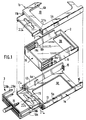
- this storage assembly movable, has the following structure. It essentially consists of a box comprising in the present case two identical elementary parts (1a, 1b), obtained by molding a plastic material, such as for example polycarbonate. These two elementary parts (1a, 1b) define, when assembled edge to edge, a space closed, open on one of its end faces and inside which is a drawer (2), also obtained by molding a plastic material (polycarbonate).
- the drawer (2) has dimensions such that it can slide inside the enclosure and take two positions, one retracted inside the box (position shown in Figure 1), the other outlet of the latter but not dissociated in order to take the object it contains.
- these two elements: case (1a, 1b) and drawer (2) comprise means which make it possible, in cooperation, to keep them normally locked in the closed position of the drawer.
- These means are capable of being actuated by an assembly, designated by the general reference (3) for unlocking the drawer, outside the presentation site, for example at the cash desk.
- the means for locking the drawer (2) relative to the box form an integral part of said case and drawer and are also obtained directly in the molding operation of these elements.
- Such means are constituted by two fixed stops or ramps (4a, 4b - 5a, 5b) on the internal walls of the enclosure or cabinet (1a, 1b).
- retractable stops are provided (8a, 8b, 9a, 9b) in the walls (7,6) of said drawer (2), these stops normally projecting relative to to the external surface of said walls (7,6).
- the different stops are arranged at the same level.
- Such an unlocking assembly consists essentially of two pairs of pushers (29a, 29b), (10a, 10b) capable of being introduced inside the enclosure and this, through orifices (11a, 11b - 21a, 21b) provided on the rear wall of the cabinet, so that, when sliding, they pass through the space between the external walls (6,7) of the drawer (2) and the internal walls (12 , 13) of the housing and, during this movement, push the protruding raised parts of the retractable stops (8a, 8b, 9a, 9b) and this, so that they are pushed towards the inside of the drawer.
- an additional central pushbutton (14) comes, passing through an orifice (15) provided on the rear face of the cabinet, to rest on the rear face (16) of the drawer and the pushes forward through the front hole of said cabinet.
- the drawer (2) is held inside the box by the presence of the extreme stops (15,16) against which the protruding parts come to bear in relief of the lateral flexible parts (9a, 9b; 8a, 8b).
- the production of such a storage assembly is, as said above, obtained by molding.
- the cabinet is made up of two identical parts (1a, 1b) which are joined together by welding their peripheral edges after the drawer (2) has been placed inside the recess defined between these two elementary parts (1a, 1b).
- the width of the drawer (2) is such that it can slide while resting on the ends of the fixed stops (4a, 4b-5a, 5b). Furthermore, if the visible faces of the box can be full, according to an embodiment as illustrated in FIG. 1, they can have windows open on the side faces of the box. (windows 18,19) or at the end of the bottom of the drawer (2) (window 20) on the one hand, to improve the aesthetics and on the other hand, to facilitate the taking of the object inside the drawer.
- the assembly according to the invention is designed so as to be able to present it in a conventional manner on a sales site in the manner of a blister.
- a form of use is made possible by the presence of protruding parts, obtained directly by molding on the elementary parts (1a, 1b) constituting the box and which include openings (22a, 22b) allowing the passage of a rod. display stand.
- additional means can be provided in the spaces into which the pushers are introduced, for example small protrusions forming baffles which, while allowing the unlocking means to pass, can make it possible to deflect rods such as needles which would be introduced by an indelicate person who would like to appropriate the article contained in the storage assembly according to the invention.
Description
La présente invention a trait à un ensemble de rangement, déplaçable, permettant d'assurer la présentation et la protection d'articles divers, tels que notamment des cassettes audio ou vidéo, livres, disques compacts... sur le site où ils doivent être vendus.The present invention relates to a storage assembly, movable, to ensure the presentation and protection of various items, such as in particular audio or video cassettes, books, compact discs ... on the site where they must be sold.
A ce jour, pour la commercialisation de tels articles, diverses solutions sont proposées pour en assurer à la fois le stockage et la protection ainsi que la présentation sur le site de vente.To date, for the marketing of such articles, various solutions are proposed to ensure both storage and protection as well as presentation on the sales site.
L'une des solutions les plus répandues consiste à réaliser un emballage fermé du type "blister" autour de l'article, un tel emballage étant constitué essentiellement par une coquille transparente, fixée sur un fond (plaque carton en général) et qui comporte à sa partie supérieure une ouverture ou un crochet servant à le suspendre sur les broches support d'un présentoir. Dans un tel type de présentation, l'un des problèmes qui se posent est celui de la protection contre les vols. Pour résoudre ce problème, divers systèmes ont été proposés, ces systèmes faisant appel à des solutions électromagnétiques ou radioélectriques. D'une manière générale, ce genre de système est constitué par une barrette magnétisée de façon permanente ou provisoire (dans ce cas, il existe une possibilité de magnétisation et de démagnétisation) ou une pastille émettant des ondes radioélectriques. Si l'acheteur ne fait pas "valider" le produit qu'il désire acquérir, lorsqu'il traverse un portillon récepteur généralement situé à la sortie du magasin, il déclenche une alarme et est immédiatement repéré. La barrette ou la pastille est généralement cachée dans l'emballage, mais la personne indélicate peut sans grand problème découvrir l'emplacement de ladite barrette ou pastille, la décoller et la jeter, de telle sorte que lorsqu'elle franchit le portillon détecteur, le produit ne peut pas être détecté. Par suite, un tel système manque de fiabilité. Outre cet inconvénient, l'adjonction au produit lui-même d'un système antivol augmente les coûts, non seulement par l'obligation de mise en place du système antivol sur chaque produit, mais également par le fait que ledit système antivol ne sert qu'une seule fois.One of the most widespread solutions consists in making a closed blister-type packaging around the article, such packaging consisting essentially of a transparent shell, fixed to a bottom (cardboard plate in general) and which comprises its upper part an opening or a hook used to hang it on the support pins of a display. In such a presentation, one of the problems that arises is that of protection against theft. To solve this problem, various systems have been proposed, these systems calling on electromagnetic or radioelectric solutions. Generally, this kind of system is constituted by a bar magnetized permanently or temporarily (in this case, there is a possibility of magnetization and demagnetization) or a pellet emitting radio waves. If the buyer does not "validate" the product he wishes to acquire, when he crosses a receiving gate generally located at the exit of the store, he triggers an alarm and is immediately spotted. The strip or patch is generally hidden in the packaging, but the unscrupulous person can without great problem discover the location of said strip or patch, peel it off and throw it away, so that when it passes through the detector gate, the product cannot be detected. As a result, such a system lacks reliability. In addition to this drawback, the addition to the product itself of an anti-theft system increases the costs, not only by the obligation to install the anti-theft system on each product, but also by the fact that said anti-theft system is only used 'only once.
Or on a trouvé, et c'est ce qui fait l'objet de la présente invention, un ensemble de rangement et de présentation qui permet de résoudre ces problèmes et qui également est très esthétique, simple à fabriquer et à utiliser, et permet éventuellement, selon une forme de réalisation, d'assurer le maintien des articles mis en vente de manière conventionnelle sur un présentoir à la façon d'un "blister" suspendu.Now we have found, and this is what is the subject of the present invention, a set of storage and presentation which makes it possible to solve these problems and which also is very aesthetic, simple to manufacture and to use, and possibly allows , according to one embodiment, to ensure the maintenance of articles sold in a conventional manner on a display in the manner of a hanging "blister".
D'une manière générale, l'invention concerne donc un ensemble de rangement, déplaçable, permettant d'assurer la présentation et la protection d'articles divers (cassettes, disques, livres..) sur un site de vente, ledit ensemble étant constitué essentiellement par un coffret (ou enceinte) renfermant un tiroir coulissant, destiné à recevoir le produit, ledit tiroir pouvant prendre deux positions, l'une escamotée à l'intérieur du coffret, l'autre sortie de ce dernier, mais non désolidarisée, afin de pouvoir prendre l'objet qu'il renferme, le coffret externe et le tiroir qu'il renferme comportant des moyens permettant, en coopération, de maintenir ces deux éléments bloqués en position fermée, moyens susceptibles d'être actionnés par un ensemble de déverrouillage du tiroir et ce, en dehors du site de présentation (par exemple à la caisse) :
- lesdits moyens de blocage en position fermée du tiroir par rapport à l'enceinte étant constitués :
- . par au moins une butée ou rampe fixe prévue sur les parois latérales internes de l'enceinte ;
- . par au moins une butée escamotable dans les parois du tiroir, maintenue normalement débordante par rapport à ces dernières, et située à un niveau correspondant à celui des butées ou rampes fixes de l'enceinte et,
- les moyens de déverrouillage étant constitués par au moins deux poussoirs, susceptibles d'être introduits simultanément à l'intérieur de l'enceinte et qui, lors de leur déplacement, s'appuient contre les butées ou rampes escamotables prévues dans les parois du tiroir pour les repousser vers l'extérieur de ces dernières.
- said blocking means in the closed position of the drawer relative to the enclosure being made up:
- . by at least one fixed stop or ramp provided on the internal lateral walls of the enclosure;
- . by at least one retractable stop in the walls of the drawer, kept normally projecting with respect to the latter, and situated at a level corresponding to that of the fixed stops or ramps of the enclosure and,
- the unlocking means being constituted by at least two pushers, capable of being introduced simultaneously inside the enclosure and which, during their movement, bear against the retractable stops or ramps provided in the walls of the drawer for push them out of the latter.
Selon une forme de réalisation préférentielle conforme à l'invention, les éléments de blocage en position fermée du tiroir par rapport à l'enceinte sont constitués par deux paires de butées fixes et deux paires de butées escamotables correspondantes, l'ensemble extracteur comportant dans ce cas deux paires d'éléments poussoirs parallèles permettant d'agir simultanément sur les rampes ou butées escamotables prévues sur les parois du tiroir ; dans ce mode de réalisation, un poussoir additionnel ou éjecteur agit sur le fond du tiroir pour le repousser vers l'avant, afin de permettre la prise de l'objet (cassette par exemple) qu'il contient.According to a preferred embodiment according to the invention, the locking elements in the closed position of the drawer relative to the enclosure are constituted by two pairs of fixed stops and two pairs of corresponding retractable stops, the extractor assembly comprising in this in the case of two pairs of parallel pusher elements making it possible to act simultaneously on the retractable ramps or stops provided on the walls of the drawer; in this embodiment, an additional pusher or ejector acts on the bottom of the drawer to push it forward, in order to allow the object (cassette for example) to be taken up.
Par ailleurs, selon cette forme de réalisation, l'enceinte ou coffret ainsi que le tiroir sont réalisés à partir d'une matière plastique moulée (polycarbonate), l'enceinte étant constituée de deux parties identiques assemblées bord à bord par tout moyen approprié, tel que soudure aux ultra-sons, après mise en place du tiroir entre ces deux parties élémentaires.Furthermore, according to this embodiment, the enclosure or cabinet as well as the drawer are made from a molded plastic material (polycarbonate), the enclosure being made up of two identical parts. assembled edge to edge by any suitable means, such as ultrasonic welding, after the drawer has been put in place between these two elementary parts.
Grâce à une telle conception, il est possible de disposer dans une zone inaccessible par un utilisateur, par exemple entre la face inférieure du tiroir et le fond du coffret, un système de détection contre le vol, tel que par exemple une barrette magnétisée ou une pastille émettant des ondes radioélectriques.Thanks to such a design, it is possible to have in a zone inaccessible to a user, for example between the underside of the drawer and the bottom of the cabinet, a system for detecting theft, such as for example a magnetized bar or a pellet emitting radio waves.
L'invention et les avantages qu'elle apporte seront cependant mieux compris grâce à l'exemple de réalisation donné ci-après à titre indicatif mais non limitatif, et qui est illustré par les schémas annexés dans lesquels :
- la figure 1 est une vue en perspective éclatée des différents éléments entrant dans la réalisation d'un ensemble de rangement conforme à l'invention ;
- la figure 2 est une vue de détail, en coupe, montrant la manière dont est réalisé le déverrouillage du tiroir dans un ensemble conforme à l'invention lorsque l'on souhaite en extraire l'objet qu'il contient.
- Figure 1 is an exploded perspective view of the various elements involved in the production of a storage assembly according to the invention;
- Figure 2 is a detail view, in section, showing the manner in which the unlocking of the drawer is carried out in an assembly according to the invention when it is desired to extract the object which it contains.
Si l'on se reporte aux schémas annexés et plus particulièrement à la figure 1, figure dans laquelle les différents éléments constituant l'ensemble conforme à l'invention sont représentés en vue éclatée, représentés de façon partielle pour l'une des parties de l'ensemble formant coffret, cet ensemble de rangement, déplaçable, a la structure suivante. Il est constitué essentiellement par un coffret comprenant dans le cas présent deux pièces élémentaires (1a,1b) identiques, obtenues par moulage d'une matière plastique, telle que par exemple du polycarbonate. Ces deux pièces élémentaires (1a,1b) définissent, lorsqu'elles sont assemblées bord à bord, un espace fermé, ouvert sur l'une de ses faces extrêmes et à l'intérieur duquel est disposé un tiroir (2), également obtenu par moulage d'une matière plastique (polycarbonate). Le tiroir (2) a des dimensions telles qu'il puisse coulisser à l'intérieur de l'enceinte et prendre deux positions, l'une escamotée à l'intérieur du coffret (position représentée à la figure 1), l'autre sortie de ce dernier mais non désolidarisée afin de prendre l'objet qu'il renferme. Conformément à l'invention, ces deux éléments : boitier (1a,1b) et tiroir (2) comportent des moyens qui permettent, en coopération, de les maintenir normalement bloqués en position fermée du tiroir. Ces moyens sont susceptibles d'être actionnés par un ensemble, désigné par la référence générale (3) de déverrouillage du tiroir et ce, en dehors du site de présentation, par exemple à la caisse.If reference is made to the appended diagrams and more particularly to FIG. 1, a figure in which the various elements constituting the assembly according to the invention are shown in exploded view, represented partially for one of the parts of the 'assembly forming a box, this storage assembly, movable, has the following structure. It essentially consists of a box comprising in the present case two identical elementary parts (1a, 1b), obtained by molding a plastic material, such as for example polycarbonate. These two elementary parts (1a, 1b) define, when assembled edge to edge, a space closed, open on one of its end faces and inside which is a drawer (2), also obtained by molding a plastic material (polycarbonate). The drawer (2) has dimensions such that it can slide inside the enclosure and take two positions, one retracted inside the box (position shown in Figure 1), the other outlet of the latter but not dissociated in order to take the object it contains. According to the invention, these two elements: case (1a, 1b) and drawer (2) comprise means which make it possible, in cooperation, to keep them normally locked in the closed position of the drawer. These means are capable of being actuated by an assembly, designated by the general reference (3) for unlocking the drawer, outside the presentation site, for example at the cash desk.
Dans la forme de réalisation illustrée, les moyens de blocage du tiroir (2) par rapport au coffret, forment partie intégrante dudit boitier et tiroir et sont également obtenus directement dans l'opération de moulage de ces éléments. De tels moyens sont constitués par deux butées ou rampes fixes (4a,4b - 5a,5b) sur les parois internes de l'enceinte ou coffret (1a,1b). Sur les parois latérales (7,6) correspondantes du tiroir (2), sont prévues des butées escamotables (8a,8b, 9a,9b) dans les parois (7,6) dudit tiroir (2), ces butées débordant normalement par rapport à la surface externe desdites parois (7,6). Les différentes butées sont disposées à un même niveau.In the illustrated embodiment, the means for locking the drawer (2) relative to the box, form an integral part of said case and drawer and are also obtained directly in the molding operation of these elements. Such means are constituted by two fixed stops or ramps (4a, 4b - 5a, 5b) on the internal walls of the enclosure or cabinet (1a, 1b). On the corresponding side walls (7,6) of the drawer (2), retractable stops are provided (8a, 8b, 9a, 9b) in the walls (7,6) of said drawer (2), these stops normally projecting relative to to the external surface of said walls (7,6). The different stops are arranged at the same level.
Grâce à un tel ensemble de butées fixes et de butées escamotables, il est possible, comme cela sera vu dans la suite de la description, de maintenir le tiroir normalement bloqué à l'intérieur du coffret et de pouvoir l'extraire, en dehors du site de présentation, au moyen d'un ensemble de déverrouillage (3). Un tel ensemble de déverrouillage est constitué essentiellement par deux paires de poussoirs (29a,29b), (10a,10b) susceptibles d'être introduits à l'intérieur de l'enceinte et ce, au travers d'orifices (11a, 11b - 21a, 21b) prévus sur la paroi arrière du coffret et ce, de telle sorte, qu'en coulissant, ils passent dans l'espace compris entre les parois extérieures (6,7) du tiroir (2) et les parois internes (12,13) du boitier et, lors de ce déplacement, viennent repousser les parties en relief débordantes des butées escamotables (8a,8b, 9a, 9b) et ce, de telle sorte qu'elles se trouvent repoussées vers l'intérieur du tiroir. Simultanément à cette action des poussoirs latéraux, un poussoir central additionnel (14) vient, en passant au travers d'un orifice (15) prévu sur la face arrière du coffret, s'appuyer sur la face arrière (16) du tiroir et le repousse vers l'avant au travers de l'orifice frontal dudit coffret. En position extrême, le tiroir (2) est maintenu à l'intérieur du coffret par la présence des butées extrêmes (15,16) contre lesquelles viennent s'appuyer les parties débordantes en relief des parties flexibles latérales (9a,9b ; 8a,8b). La réalisation d'un tel ensemble de rangement est, comme dit précédemment, obtenue par moulage. Le coffret est constitué de deux pièces identiques (1a,1b) qui sont réunies entre elles par soudure de leurs bords périphériques après mise en place du tiroir (2) à l'intérieur de l'évidement défini entre ces deux parties élémentaires (1a,1b). La largeur du tiroir (2) est telle qu'il puisse coulisser en prenant appui sur les extrémités des butées fixes (4a,4b-5a,5b). Par ailleurs, si les faces visibles du coffret peuvent être pleines, selon une forme de réalisation telle qu'illustrée à la figure 1, elles peuvent comporter des fenêtres ouvertes sur les faces latérales du coffret (fenêtres 18,19) ou à l'extrémité du fond du tiroir (2) (fenêtre 20) pour d'une part, améliorer l'esthétique et d'autre part, faciliter la prise de l'objet à l'intérieur du tiroir.With such a set of fixed stops and retractable stops, it is possible, as will be seen in the following description, to keep the drawer normally locked inside the box and to be able to extract it, outside the presentation site, using a unlocking assembly (3). Such an unlocking assembly consists essentially of two pairs of pushers (29a, 29b), (10a, 10b) capable of being introduced inside the enclosure and this, through orifices (11a, 11b - 21a, 21b) provided on the rear wall of the cabinet, so that, when sliding, they pass through the space between the external walls (6,7) of the drawer (2) and the internal walls (12 , 13) of the housing and, during this movement, push the protruding raised parts of the retractable stops (8a, 8b, 9a, 9b) and this, so that they are pushed towards the inside of the drawer. Simultaneously with this action of the lateral pushers, an additional central pushbutton (14) comes, passing through an orifice (15) provided on the rear face of the cabinet, to rest on the rear face (16) of the drawer and the pushes forward through the front hole of said cabinet. In the extreme position, the drawer (2) is held inside the box by the presence of the extreme stops (15,16) against which the protruding parts come to bear in relief of the lateral flexible parts (9a, 9b; 8a, 8b). The production of such a storage assembly is, as said above, obtained by molding. The cabinet is made up of two identical parts (1a, 1b) which are joined together by welding their peripheral edges after the drawer (2) has been placed inside the recess defined between these two elementary parts (1a, 1b). The width of the drawer (2) is such that it can slide while resting on the ends of the fixed stops (4a, 4b-5a, 5b). Furthermore, if the visible faces of the box can be full, according to an embodiment as illustrated in FIG. 1, they can have windows open on the side faces of the box. (
Dans l'exemple de réalisation illustré, l'ensemble conforme à l'invention est conçu de manière à pouvoir le présenter de façon conventionnelle sur un site de vente à la manière d'un blister. Une telle forme d'utilisation est rendue possible par la présence de parties débordantes, obtenues directement par moulage sur les parties élémentaires (1a,1b) constituant le coffret et qui comportent des ouvertures (22a,22b) permettant le passage d'une tige de présentoir.In the illustrated embodiment, the assembly according to the invention is designed so as to be able to present it in a conventional manner on a sales site in the manner of a blister. Such a form of use is made possible by the presence of protruding parts, obtained directly by molding on the elementary parts (1a, 1b) constituting the box and which include openings (22a, 22b) allowing the passage of a rod. display stand.
Bien entendu, l'invention n'est pas limitée à l'exemple de réalisation décrit précédemment, mais elle en couvre toutes les variantes réalisées dans le même esprit.Of course, the invention is not limited to the embodiment described above, but it covers all the variants produced in the same spirit.
Ainsi, il pourrait bien entendu être envisagé de réaliser des ensembles comportant plus de deux paires de butées fixes et de butées escamotables correspondantes, par exemple trois paires, les moyens de déverrouillage comportant alors non pas deux poussoirs mais trois.Thus, it could of course be envisaged to produce assemblies comprising more than two pairs of fixed stops and corresponding retractable stops, for example three pairs, the unlocking means then comprising not two pushers but three.
Par ailleurs, des moyens additionnels peuvent être prévus dans les espaces dans lesquels sont introduits les poussoirs, par exemple de petites protubérances formant des chicanes qui, tout en laissant passer les moyens de déverrouillage, peuvent permettre de dévier des tiges telles que aiguilles qui seraient introduites par une personne indélicate et qui souhaiterait s'approprier l'article contenu dans l'ensemble de rangement conforme à l'invention.Furthermore, additional means can be provided in the spaces into which the pushers are introduced, for example small protrusions forming baffles which, while allowing the unlocking means to pass, can make it possible to deflect rods such as needles which would be introduced by an indelicate person who would like to appropriate the article contained in the storage assembly according to the invention.
Claims (4)
- Movable storage assembly for the display and protection of various articles (cassettes, records, books, etc.) at a selling site, the said assembly consisting essentially of a case (1a, 1b) enclosing a sliding drawer (2), intended to receive the product, the said drawer (2) being able to assume two positions, one retracted inside the case, the other outside the latter but not detached, in order to be able to take the object it encloses, the outer case (1a, 1b) and the drawer (2) it encloses including means making it possible, in cooperation, to hold these two elements blocked in a closed position, means capable of being actuated by an unlocking assembly (3) of the drawer (2), this being outside the display site (for example at the cash desk):- the said means for blocking the drawer (2) in the closed position with respect to the chamber (1a, 1b) consisting:. of at least one stop or fixed ramp (4a, 4b-5a, 5b) provided on the inner lateral walls of the chamber or case (1a-1b);. of at least one retractable stop (8a, 8b-9a, 9b) in the walls of the drawer, normally held so as to project with respect to said walls, and located at a level corresponding to that of the fixed stops or ramps of the chamber, and- the unlocking means (3) consisting of at least two pushers (29a, 29b - 10a, 10b) capable of being introduced simultaneously inside the chamber (1a, 1b) and which, when displaced, bear against the retractable stops or ramps (8a, 8b - 9a, 9b) provided in the walls (7, 6) of the drawer (2) in order to push them towards the outside of said walls.
- Storage assembly according to Claim 1, characterized in that the elements for blocking the drawer (2) in the closed position with respect to the chamber (1a, 1b) consist of two pairs of fixed stops (4a, 4b; 5a, 5b) and two pairs of corresponding retractable stops (8a, 8b; 9a, 9b), the extractor assembly (3) including two pairs of parallel pusher elements (29a, 29b, 10a, 10b) making it possible to act simultaneously on the retractable ramps or stops (8a, 8b; 9a, 9b) provided on the walls of the drawer (2) as well as an additional pusher (14) or ejector which acts on the bottom (16) of the drawer in order to push it forwards, in order to enable the object (for example, a cassette) which it contains to be gripped.
- Storage assembly according to one of Claims 1 and 2, characterized in that the chamber or case (1a, 1b) and the drawer (2) are produced from a moulded plastic (polycarbonate), the chamber consisting of two identical parts (1a, 1b) assembled edge-to-edge by any appropriate means such as ultrasonic welding after positioning of the drawer (2) between these two elementary parts (1a, 1b).
- Storage assembly according to one of Claims 1 to 3, characterized in that it includes an anti-theft detection system, such as a magnetic bar or a chip emitting radioelectric waves arranged in a zone inaccessible to a user, such as between the lower face of the drawer (2) and the base of the case (1).
Applications Claiming Priority (2)
| Application Number | Priority Date | Filing Date | Title |
|---|---|---|---|
| FR9006897 | 1990-05-29 | ||
| FR9006897A FR2662666B1 (en) | 1990-05-29 | 1990-05-29 | STORAGE ASSEMBLY FOR ENSURING THE PRESENTATION AND PROTECTION OF VARIOUS ITEMS ON A SALE SITE. |
Publications (2)
| Publication Number | Publication Date |
|---|---|
| EP0461049A1 EP0461049A1 (en) | 1991-12-11 |
| EP0461049B1 true EP0461049B1 (en) | 1994-03-09 |
Family
ID=9397234
Family Applications (1)
| Application Number | Title | Priority Date | Filing Date |
|---|---|---|---|
| EP19910420168 Expired - Lifetime EP0461049B1 (en) | 1990-05-29 | 1991-05-28 | Unit for the display and protection of various articles at a selling site |
Country Status (3)
| Country | Link |
|---|---|
| EP (1) | EP0461049B1 (en) |
| DE (1) | DE69101341T2 (en) |
| FR (1) | FR2662666B1 (en) |
Families Citing this family (10)
| Publication number | Priority date | Publication date | Assignee | Title |
|---|---|---|---|---|
| AU648490B3 (en) * | 1993-08-23 | 1994-04-21 | Plastech Industries Pty Ltd | A security container |
| FR2711311B1 (en) * | 1993-10-19 | 1996-01-12 | Ambre Sa Montres | Method for protecting objects offered for sale in shops from theft and means of implementation. |
| FR2722028B1 (en) * | 1994-06-30 | 1996-08-09 | Cedec Sa | ANTI-THEFT BOX |
| JP2681156B2 (en) * | 1994-12-05 | 1997-11-26 | 株式会社エムジーエンジニアリング | Theft monitoring case and jig for theft monitoring case |
| FR2757145B1 (en) * | 1996-12-13 | 1999-03-05 | Lefebure | HOUSING OPENING APPARATUS |
| US5956981A (en) * | 1997-02-18 | 1999-09-28 | Alpha Enterprises, Inc. | Universal opener |
| KR100269853B1 (en) * | 1997-10-16 | 2000-10-16 | 임옥빈 | Compact disk case with thief-protecting function |
| AU3869100A (en) * | 1999-03-09 | 2000-09-28 | Alpha Enterprises, Inc. | Adapter for security package |
| GB2362423B (en) * | 2000-05-17 | 2003-11-12 | Maurice Henry Whittle | Security apparatus |
| EP2246507A1 (en) * | 2006-03-30 | 2010-11-03 | MeadWestvaco Corporation | Universal retail security package with cover window |
Family Cites Families (3)
| Publication number | Priority date | Publication date | Assignee | Title |
|---|---|---|---|---|
| US3871516A (en) * | 1973-06-11 | 1975-03-18 | J L Marsh Inc | Antitheft packaging device |
| DE2837610C3 (en) * | 1978-08-29 | 1981-11-12 | Orschler Produktion Kg, 8751 Stockstadt | Portable display container for displaying at least one sales item received therein |
| FR2508301A1 (en) * | 1981-06-26 | 1982-12-31 | Boullier Bernard | Antitheft display stand for audio cassettes - consists of base and lid locked together by side flaps, slots, studs and notches |
-
1990
- 1990-05-29 FR FR9006897A patent/FR2662666B1/en not_active Expired - Lifetime
-
1991
- 1991-05-28 EP EP19910420168 patent/EP0461049B1/en not_active Expired - Lifetime
- 1991-05-28 DE DE1991601341 patent/DE69101341T2/en not_active Expired - Fee Related
Also Published As
| Publication number | Publication date |
|---|---|
| FR2662666B1 (en) | 1992-08-28 |
| DE69101341T2 (en) | 1994-06-16 |
| EP0461049A1 (en) | 1991-12-11 |
| DE69101341D1 (en) | 1994-04-14 |
| FR2662666A1 (en) | 1991-12-06 |
Similar Documents
| Publication | Publication Date | Title |
|---|---|---|
| EP0098216B1 (en) | Receptacle for self-service sale articles with a combined mechanical and magnetic unlocking lid | |
| BE1008308A6 (en) | Box anti-theft a closure and compact magnetic business in an action for a combined action mechanics. | |
| EP0461049B1 (en) | Unit for the display and protection of various articles at a selling site | |
| FR2498357A1 (en) | MAGNETIC MEMORY MEMORY STORAGE CABINET | |
| FR2476329A1 (en) | BOX FOR SAME SIZE VIEWS | |
| FR2503914A1 (en) | CONTAINER FOR MAGNETIC TAPE CASSETTE | |
| FR2539907A1 (en) | Magnetic tape cassette | |
| FR2538230A1 (en) | BOX | |
| FR2475268A1 (en) | CASE FOR DISC-SHAPED RECORDING MEDIUM | |
| EP0300109B1 (en) | Inviolable jacket-case assembly for lending or selling | |
| FR2811115A1 (en) | ANTI-THEFT GOODS EQUIPMENT | |
| FR2688483A1 (en) | Anti-theft case for an article contained in a flat box | |
| FR2588794A1 (en) | CASSETTE TYPE STAPLER | |
| WO2006045757A1 (en) | Plate and box for at least one pair of compact disks | |
| EP1559103B1 (en) | Package for a disc-shaped digital recording medium | |
| FR2651975A1 (en) | Powder box (compact) | |
| BE894483A (en) | Case for storing cassettes - has separate compartments held in drawer by ratchet action released by pressure | |
| FR2765381A1 (en) | Compact disk casing | |
| CH673380A5 (en) | ||
| EP3585961B1 (en) | Casing having a slide for locking and immobilizing in a closed or open position | |
| FR2621893A1 (en) | Anti-theft display and protection box for case. | |
| FR2671958A1 (en) | Display device for flat rigid objects | |
| FR2813859A1 (en) | Display package for set of door furniture comprises intermediate plate positioned between door plates with pins which fit into their screw holes, slot at top allowing package to be hung up for display | |
| FR2656779A1 (en) | Case for storing pieces, tokens, cards, labels etc., or similar articles which may be associated with a key-holder ring | |
| FR2639744A1 (en) | Anti-theft packaging for a flat article of rectangular general shape |
Legal Events
| Date | Code | Title | Description |
|---|---|---|---|
| PUAI | Public reference made under article 153(3) epc to a published international application that has entered the european phase |
Free format text: ORIGINAL CODE: 0009012 |
|
| AK | Designated contracting states |
Kind code of ref document: A1 Designated state(s): BE CH DE ES GB GR IT LI |
|
| 17P | Request for examination filed |
Effective date: 19920522 |
|
| 17Q | First examination report despatched |
Effective date: 19930504 |
|
| RAP3 | Party data changed (applicant data changed or rights of an application transferred) |
Owner name: INTERCO |
|
| GRAA | (expected) grant |
Free format text: ORIGINAL CODE: 0009210 |
|
| AK | Designated contracting states |
Kind code of ref document: B1 Designated state(s): BE CH DE ES GB GR IT LI |
|
| PG25 | Lapsed in a contracting state [announced via postgrant information from national office to epo] |
Ref country code: IT Free format text: LAPSE BECAUSE OF FAILURE TO SUBMIT A TRANSLATION OF THE DESCRIPTION OR TO PAY THE FEE WITHIN THE PRESCRIBED TIME-LIMIT;WARNING: LAPSES OF ITALIAN PATENTS WITH EFFECTIVE DATE BEFORE 2007 MAY HAVE OCCURRED AT ANY TIME BEFORE 2007. THE CORRECT EFFECTIVE DATE MAY BE DIFFERENT FROM THE ONE RECORDED. Effective date: 19940309 Ref country code: GB Effective date: 19940309 Ref country code: GR Free format text: LAPSE BECAUSE OF FAILURE TO SUBMIT A TRANSLATION OF THE DESCRIPTION OR TO PAY THE FEE WITHIN THE PRESCRIBED TIME-LIMIT Effective date: 19940309 Ref country code: ES Free format text: THE PATENT HAS BEEN ANNULLED BY A DECISION OF A NATIONAL AUTHORITY Effective date: 19940309 |
|
| REF | Corresponds to: |
Ref document number: 69101341 Country of ref document: DE Date of ref document: 19940414 |
|
| PGFP | Annual fee paid to national office [announced via postgrant information from national office to epo] |
Ref country code: CH Payment date: 19940516 Year of fee payment: 4 |
|
| PGFP | Annual fee paid to national office [announced via postgrant information from national office to epo] |
Ref country code: DE Payment date: 19940526 Year of fee payment: 4 |
|
| PGFP | Annual fee paid to national office [announced via postgrant information from national office to epo] |
Ref country code: BE Payment date: 19940610 Year of fee payment: 4 |
|
| GBV | Gb: ep patent (uk) treated as always having been void in accordance with gb section 77(7)/1977 [no translation filed] |
Effective date: 19940309 |
|
| PLBE | No opposition filed within time limit |
Free format text: ORIGINAL CODE: 0009261 |
|
| STAA | Information on the status of an ep patent application or granted ep patent |
Free format text: STATUS: NO OPPOSITION FILED WITHIN TIME LIMIT |
|
| 26N | No opposition filed | ||
| PG25 | Lapsed in a contracting state [announced via postgrant information from national office to epo] |
Ref country code: BE Effective date: 19950531 Ref country code: CH Effective date: 19950531 Ref country code: LI Effective date: 19950531 |
|
| BERE | Be: lapsed |
Owner name: INTERCO Effective date: 19950531 |
|
| REG | Reference to a national code |
Ref country code: CH Ref legal event code: PL |
|
| PG25 | Lapsed in a contracting state [announced via postgrant information from national office to epo] |
Ref country code: DE Effective date: 19960201 |