EP0461018B1 - Method and device for controlling the thickness and cohesion of a duplex tube interface - Google Patents
Method and device for controlling the thickness and cohesion of a duplex tube interface Download PDFInfo
- Publication number
- EP0461018B1 EP0461018B1 EP91401439A EP91401439A EP0461018B1 EP 0461018 B1 EP0461018 B1 EP 0461018B1 EP 91401439 A EP91401439 A EP 91401439A EP 91401439 A EP91401439 A EP 91401439A EP 0461018 B1 EP0461018 B1 EP 0461018B1
- Authority
- EP
- European Patent Office
- Prior art keywords
- tube
- thickness
- core
- interface
- cladding
- Prior art date
- Legal status (The legal status is an assumption and is not a legal conclusion. Google has not performed a legal analysis and makes no representation as to the accuracy of the status listed.)
- Expired - Lifetime
Links
Images


Classifications
-
- G—PHYSICS
- G01—MEASURING; TESTING
- G01N—INVESTIGATING OR ANALYSING MATERIALS BY DETERMINING THEIR CHEMICAL OR PHYSICAL PROPERTIES
- G01N27/00—Investigating or analysing materials by the use of electric, electrochemical, or magnetic means
- G01N27/72—Investigating or analysing materials by the use of electric, electrochemical, or magnetic means by investigating magnetic variables
-
- G—PHYSICS
- G01—MEASURING; TESTING
- G01B—MEASURING LENGTH, THICKNESS OR SIMILAR LINEAR DIMENSIONS; MEASURING ANGLES; MEASURING AREAS; MEASURING IRREGULARITIES OF SURFACES OR CONTOURS
- G01B5/00—Measuring arrangements characterised by the use of mechanical techniques
- G01B5/02—Measuring arrangements characterised by the use of mechanical techniques for measuring length, width or thickness
-
- G—PHYSICS
- G01—MEASURING; TESTING
- G01B—MEASURING LENGTH, THICKNESS OR SIMILAR LINEAR DIMENSIONS; MEASURING ANGLES; MEASURING AREAS; MEASURING IRREGULARITIES OF SURFACES OR CONTOURS
- G01B17/00—Measuring arrangements characterised by the use of infrasonic, sonic or ultrasonic vibrations
- G01B17/02—Measuring arrangements characterised by the use of infrasonic, sonic or ultrasonic vibrations for measuring thickness
- G01B17/025—Measuring arrangements characterised by the use of infrasonic, sonic or ultrasonic vibrations for measuring thickness for measuring thickness of coating
-
- G—PHYSICS
- G01—MEASURING; TESTING
- G01N—INVESTIGATING OR ANALYSING MATERIALS BY DETERMINING THEIR CHEMICAL OR PHYSICAL PROPERTIES
- G01N29/00—Investigating or analysing materials by the use of ultrasonic, sonic or infrasonic waves; Visualisation of the interior of objects by transmitting ultrasonic or sonic waves through the object
- G01N29/04—Analysing solids
- G01N29/11—Analysing solids by measuring attenuation of acoustic waves
-
- G—PHYSICS
- G01—MEASURING; TESTING
- G01N—INVESTIGATING OR ANALYSING MATERIALS BY DETERMINING THEIR CHEMICAL OR PHYSICAL PROPERTIES
- G01N29/00—Investigating or analysing materials by the use of ultrasonic, sonic or infrasonic waves; Visualisation of the interior of objects by transmitting ultrasonic or sonic waves through the object
- G01N29/22—Details, e.g. general constructional or apparatus details
- G01N29/221—Arrangements for directing or focusing the acoustical waves
-
- G—PHYSICS
- G01—MEASURING; TESTING
- G01N—INVESTIGATING OR ANALYSING MATERIALS BY DETERMINING THEIR CHEMICAL OR PHYSICAL PROPERTIES
- G01N29/00—Investigating or analysing materials by the use of ultrasonic, sonic or infrasonic waves; Visualisation of the interior of objects by transmitting ultrasonic or sonic waves through the object
- G01N29/22—Details, e.g. general constructional or apparatus details
- G01N29/24—Probes
- G01N29/2456—Focusing probes
-
- G—PHYSICS
- G01—MEASURING; TESTING
- G01N—INVESTIGATING OR ANALYSING MATERIALS BY DETERMINING THEIR CHEMICAL OR PHYSICAL PROPERTIES
- G01N2291/00—Indexing codes associated with group G01N29/00
- G01N2291/02—Indexing codes associated with the analysed material
- G01N2291/023—Solids
- G01N2291/0231—Composite or layered materials
-
- G—PHYSICS
- G01—MEASURING; TESTING
- G01N—INVESTIGATING OR ANALYSING MATERIALS BY DETERMINING THEIR CHEMICAL OR PHYSICAL PROPERTIES
- G01N2291/00—Indexing codes associated with group G01N29/00
- G01N2291/02—Indexing codes associated with the analysed material
- G01N2291/028—Material parameters
- G01N2291/02854—Length, thickness
-
- G—PHYSICS
- G01—MEASURING; TESTING
- G01N—INVESTIGATING OR ANALYSING MATERIALS BY DETERMINING THEIR CHEMICAL OR PHYSICAL PROPERTIES
- G01N2291/00—Indexing codes associated with group G01N29/00
- G01N2291/02—Indexing codes associated with the analysed material
- G01N2291/028—Material parameters
- G01N2291/02863—Electric or magnetic parameters
-
- G—PHYSICS
- G01—MEASURING; TESTING
- G01N—INVESTIGATING OR ANALYSING MATERIALS BY DETERMINING THEIR CHEMICAL OR PHYSICAL PROPERTIES
- G01N2291/00—Indexing codes associated with group G01N29/00
- G01N2291/02—Indexing codes associated with the analysed material
- G01N2291/028—Material parameters
- G01N2291/02881—Temperature
-
- G—PHYSICS
- G01—MEASURING; TESTING
- G01N—INVESTIGATING OR ANALYSING MATERIALS BY DETERMINING THEIR CHEMICAL OR PHYSICAL PROPERTIES
- G01N2291/00—Indexing codes associated with group G01N29/00
- G01N2291/04—Wave modes and trajectories
- G01N2291/042—Wave modes
- G01N2291/0421—Longitudinal waves
-
- G—PHYSICS
- G01—MEASURING; TESTING
- G01N—INVESTIGATING OR ANALYSING MATERIALS BY DETERMINING THEIR CHEMICAL OR PHYSICAL PROPERTIES
- G01N2291/00—Indexing codes associated with group G01N29/00
- G01N2291/04—Wave modes and trajectories
- G01N2291/044—Internal reflections (echoes), e.g. on walls or defects
-
- G—PHYSICS
- G01—MEASURING; TESTING
- G01N—INVESTIGATING OR ANALYSING MATERIALS BY DETERMINING THEIR CHEMICAL OR PHYSICAL PROPERTIES
- G01N2291/00—Indexing codes associated with group G01N29/00
- G01N2291/04—Wave modes and trajectories
- G01N2291/048—Transmission, i.e. analysed material between transmitter and receiver
-
- G—PHYSICS
- G01—MEASURING; TESTING
- G01N—INVESTIGATING OR ANALYSING MATERIALS BY DETERMINING THEIR CHEMICAL OR PHYSICAL PROPERTIES
- G01N2291/00—Indexing codes associated with group G01N29/00
- G01N2291/10—Number of transducers
- G01N2291/101—Number of transducers one transducer
-
- G—PHYSICS
- G01—MEASURING; TESTING
- G01N—INVESTIGATING OR ANALYSING MATERIALS BY DETERMINING THEIR CHEMICAL OR PHYSICAL PROPERTIES
- G01N2291/00—Indexing codes associated with group G01N29/00
- G01N2291/26—Scanned objects
- G01N2291/263—Surfaces
- G01N2291/2634—Surfaces cylindrical from outside
Definitions
- the invention relates to a method and a device for controlling the thickness and cohesion of the interface of a duplex tube and in particular of a zirconium alloy duplex tube used as a cladding element of a fuel rod. an assembly for a water-cooled nuclear reactor.
- the fuel assemblies of water-cooled nuclear reactors and in particular of pressurized water nuclear reactors comprise a framework in which are inserted fuel rods constituted by a sheath containing a nuclear combustible material such as uranium oxide or plutonium in the form of sintered pellets.
- the sheath produced from a zirconium alloy tube must have good resistance to corrosion under the effect of the primary fluid in circulation in contact with the outer surface of the sheath.
- the zirconium alloy constituting the plating or coating layer is different from the alloy constituting the core of the tube and contains iron as well as at least one of the vanadium, platinum and copper elements.
- This surface layer the thickness of which represents 5 to 20% of the total thickness of the wall of the sheath, can be produced by extrusion of a blank formed by an inner tube made of zirconium alloy of conventional composition on which is threaded. an outer tube having the composition of the surface layer.
- the sheath is then rolled on a mit step rolling mill to its final diameter.
- a duplex tube whose surface layer having a thickness of between 10 and 25% of the he total thickness of the sheath wall consists of a zirconium-based alloy containing tin, iron and niobium or vanadium.
- the tubular core of the duplex tube can be made of a conventional zirconium alloy in the case of the production of sheaths for fuel rods or of a zirconium-based alloy mainly containing niobium as an alloying element.
- duplex tubes which are intended to constitute sheaths for fuel rods, in particular as regards the diameter of the tube, the total thickness of the sheath, l thickness of the outer plating layer and the cohesion of the interface zone between the clad layer and the core of the tube.
- the control of the diameter and of the total thickness of the sheath can be carried out using a conventional technique consisting in measuring the difference of the propagation times of ultrasonic waves, of impulse shape, which are reflected by the external surface and by the surface internal of the tube.
- This ultrasonic control and measurement technique known as the "pulse-echo" technique is possibly adapted to take account of the cladding layer, in calculating the total thickness of the sheath.
- This improved technique does not, however, allow plating thicknesses of less than 0.4 mm to be measured, since the industrial implementation of the process under satisfactory conditions requires the use of ultrasonic waves whose frequency does not exceed 20 MHz.
- the cladding layer and the tubular core of the duplex tube consist of very low alloyed zirconium alloys which have very similar acoustic properties, so that the reflection coefficient of the acoustic waves at the plating-core interface is very low (generally less than 2%) .
- the interface echo is then very weak and is embedded in the acoustic and electronic noise of the ultrasonic signal.
- FR-A-2,534,015 has proposed a method and a measuring device making it possible to determine the thickness of a zirconium coating on a zirconium alloy tube implementing the analysis and measurement of induced currents in the plating layer of the duplex tube, by magnetic induction, using an excitation current the frequency of which is chosen as a function of the nominal thickness of the plating or coating layer of the tube.
- the selected frequency and the processing of the signals corresponding to the induced currents also make it possible to eliminate, to a certain extent, the measurement errors resulting from a variation in the width of the air gap between the excitation coil and the wall of the tube.
- this technique does not make it possible to carry out alone a control of the total thickness of the tube and of the cohesion of the interface zone between the plating or coating layer of the tube and the tubular core.
- duplex tube generally designated by the reference 1 and comprising a tubular core 2 of a zirconium alloy covered externally by a cladding layer 3 of a second zirconium alloy whose composition is different from the composition of the alloy constituting the core 2.
- the zirconium alloys constituting the core 2 and the cladding layer 3 of the duplex tube 1 are low alloyed zirconium alloys whose contents of alloy elements are less than 1% by weight for each of these elements.
- the tubular core 2 and the cladding layer 3 therefore have acoustic properties which are extremely close to one another.
- the coating or plating layer 3 has a small thickness, generally between 60 and 80 f..lm, the metallic core 2 itself having a thickness slightly less than 600 f..lm.
- a duplex tube as shown in FIG. 1 used as the sheath of a fuel rod of an assembly of a pressurized water nuclear reactor generally has an outside diameter of the order of 10 mm and a length of the order 4 m.
- FIG 2A there is shown in section, the wall of a duplex tube as shown in Figure 1 comprising a tubular core 2 covered by a layer of cladding and coating bonded to the metal core, along a cylindrical surface interface 4.
- an ultrasonic transducer 5 is used emitting a beam of ultrasonic waves 6 towards the external surface of the duplex tube constituted by the outer surface of the plating layer 3.
- the tube 1 is immersed in a coupling medium constituted by a liquid allowing the transmission of the ultrasonic waves emitted by the transducer 5.
- a part of the beam of ultrasonic waves 6 is reflected by the external surface of the duplex tube in the form of a beam 6 'which is picked up by the transducer 5 and transformed into an electrical signal which is transmitted to a processing unit 7.
- the corresponding echo 8 can be viewed on an oscillogram giving an image of its amplitude and its position on the time scale.
- the ultrasonic beam 6'a transmitted through the wall of the duplex tube is reflected, in the form of a beam 6'a, by the inner surface of the core 2 of the duplex tube.
- the ultrasonic beam 6'a is picked up by the transducer 5 which transforms it into an electrical signal and allows, thanks to the processing module 7, its display on the oscillogram of FIG. 2B, in the form of the echo signal 8a.
- the time difference between signal 8 and signal 8a corresponds to twice the travel time ⁇ T of the ultrasonic waves through the wall of the tube 1.
- An approximate value of the total thickness eg of the sheath corresponding to the thickness of the wall of the duplex tube can be obtained by assuming that the propagation speeds of the ultrasonic waves in the metallic core of the sheath and in the layer of plating are identical.
- the method of direct measurement of the propagation time of ultrasonic waves does not make it possible to measure the thickness of the plating layer ep, the coefficient of reflection of the acoustic waves at the interface 4 between the plating layer 3 and the core 2 being very weak (generally less than 2%), owing to the fact that the acoustic properties of the materials constituting the cladding layer and the core are extremely close to one another.
- the plating layer has a small thickness compared to the total thickness of the wall, so that the differences in propagation time to be taken into account are themselves very small.
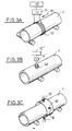
- FIGS. 3A, 3B and 3C three different embodiments are shown of an eddy current device making it possible to measure the thickness of an external cladding layer of a duplex tube 1 constituted by a metallic core covered by a plating layer, the metallic core and the plating layer being constituted by two zirconium alloys containing very small amounts of alloying elements.
- Zircaloy which is a zirconium alloy containing tin
- a variation of 1% in the tin content results in a variation of conductivity of the order of 50%.
- Such variations make it possible to apply the technique of induced currents or eddy currents to perform a thickness control of a plating layer whose composition is different from that of the metallic core coated by the plating layer.
- a coil 10 comprising a certain number of turns surrounding the tube 1.
- the coil is supplied by a multifrequency sinusoidal excitation current via a current source 11 connected to its terminals.
- the electrical signals corresponding to the induced currents are processed by a processing unit 12.
- the average value of the thickness of the cladding is measured, which includes the possible variations in thickness depending on the circumference of the tube or circumferential variations. Variations in thickness are also integrated along the length of the coil 10 or axial variations.
- the measurement is also sensitive to the centering of the tube inside the coil constituting the eddy current probe, so that this centering, even carried out in an optimized manner, risks reducing the accuracy of the measurement.
- a second measurement technique as shown in FIG. 3B consists in using a coil 14 whose axis has a radial direction relative to the tube 1.
- the device as shown in FIG. 3B makes it possible to carry out a local measurement of the thickness of the plating of the tube 1.
- FIG. 3C it is also possible to use several coils 15 similar to the coil 14 shown in FIG. 3B and fixed on a common support 16, so that the coils 15 whose axes have radial directions relative to to tube 1, are arranged around the tube, in regularly distributed circumferential positions.
- the frequency of the sinusoidal excitation signal as well as the dimensions of the windings (diameter and height) are determined so as to optimize the sensitivity of the measurements to variations in thickness of the cladding and to minimize the variations in the measurement signals due to variations in the distance between the coil and the surface of the tube, constituting an air gap.
- the method according to the invention is therefore characterized by the use of a multifrequency sinusoidal excitation signal comprising a main frequency as well as secondary frequencies.
- Two auxiliary frequencies can also be used, one of which is sensitive to the variation in conductivity of the base material constituting the core while being very insensitive to variations in the conductivity of the cladding as well as to the variations in thickness of the core. and of the cladding and the other of which is sensitive only to variations in conductivity of the cladding.
- the probe is simultaneously excited by each of the sinusoidal signals having the frequencies determined in the manner described above and the phase and amplitude measurement signals corresponding to each of the sinusoidal signals of determined frequency are digitized and processed, as indicated below. above, by a processing module and by computer means making it possible to deduce from these signals the value of the thickness of the cladding.
- the thickness of the plating is measured either by phase analysis of the signal corresponding to the eddy currents, this method presenting the advantage of being less sensitive to variations in lift-off, ie by a combined analysis of the phase and the amplitude of the signals corresponding to the eddy currents.
- e p / V p represents the travel time of the ultrasonic wave in the plating material
- (clair - e p / V p ) represents the travel time of the ultrasonic wave in the core of the tube
- (clair - e p / V p ) x Va represents the thickness of the core, for an axial position of the tube perfectly determined by means of control and measurement of axial position.
- the method according to the invention also allows detection of cohesion defects at the interface between the cladding and the core of the tube.
- Cohesion defects are flat, of negligible thickness and arranged parallel to the surface of the tube.
- An ultrasonic detection technique is therefore better suited, although the very shallow depth of the defect under the surface of the tube, corresponding to the thickness of the plating layer (between 80 and 100 ⁇ m) constitutes a difficulty in detecting cohesion defects at the interface.
- the main drawback of these reflection detection techniques lies in the need to use very high frequency ultrasound, for example at a frequency greater than 100 MHz, which corresponds to wavelengths in zirconium of less than 50 ⁇ m. .
- ultrasonic waves are emitted in directions that are substantially radial with respect to the tube, that is to say with a substantially normal incidence.
- FIG. 4A shows an ultrasonic beam 21 reflecting on the outside surface of the tube, an ultrasonic beam 22 reflecting on a defect 20 situated along the interface 4 between the cladding layer 3 and the core 2 of the tube and a beam 23 reflecting on the inner surface of the tube, the corresponding echoes 24, 25 and 26 being represented in FIG. 4B.
- the echo signal 26 reflected by the internal surface of the tube has a smaller amplitude compared to the signal 24 reflected by the external surface of the tube.
- the time difference between these two echoes corresponds to twice the travel time of the ultrasonic waves in the thickness of the tube.
- the echo signal 25 corresponding to a reflection on a fault 20 along the interface 4 has a smaller amplitude and a very small time offset with respect to the signal reflected on the outside surface of the tube, due to the very thin thickness of the layer 3 of plating.
- This first detection method is therefore limited by the fact that the defect is very close to the outer surface of the tube and therefore that the corresponding echo 25 can be mixed with the echo 24 which has a large temporal width due to the effects of the electronic amplification of the ultrasonic signal.
- a second method illustrated by FIGS. 5A and 5B consists in using a beam of ultrasonic waves 27 in oblique incidence so that this beam is first reflected by the internal surface of the tube, then by the defect 28 at the interface and a second time through the inner surface of the tube.
- the echo 29 corresponding to the re bending on the defect 28 after a first reflection on the internal surface of the tube followed by a second reflection on the internal surface of the tube has a significant time offset with respect to the echo 24.
- the echo 29 and the immediate next echo 29 ′ reflected by the internal surface of the tube are of small and equivalent amplitude and temporal width and are therefore easily separable.
- a third measurement method is illustrated in Figures 6A and 6B.
- the control is carried out from inside the tube and the ultrasonic beam is emitted at normal incidence so as to obtain a direct reflection on the fault 30.
- the echo 31 corresponding to the reflection on the defect 30 has a lesser amplitude and a significant time offset with respect to the signal reflected by the internal surface of the tube.
- this echo 31 and the immediate next echo 31 ′ resulting from the reflection on the external surface of the tube are of small and equivalent amplitudes and temporal widths and are therefore easily separable.
- FIGS. 7A, 7B, 8A and 8B illustrate a technique for detecting decohesion defects at the interface between the cladding layer 3 and the core 4 of a duplex tube 1, by transmission of an ultrasonic wave in the wall of the duplex tube constituting a fuel rod cladding, the ultrasonic wave then being reflected on the internal surface of the tube, as it is visible in FIG. 7A relating to a tube or part of a tube having no defect in decohesion.
- the oscillogram Ilogram represented in FIG. 7B comprises a bottom echo 36 whose amplitude although less than the amplitude of the input echo 35 is large.
- the application of the method to a healthy material therefore results in an almost integral transmission of the ultrasonic wave at the interface between the cladding layer 3 and the core 4 of the tube.
- the reflection at the interface 4 is indeed negligible, insofar as the acoustic impedances of the materials constituting the cladding layer 3 and the core 2 are very similar.
- the ultrasonic energy is dissipated by successive reflections in the thickness of the plating layer 3 '.
- the input echo 35 ′ is widened and translates the dissipation of the ultrasonic energy by successive reflections in the plating layer.
- the method therefore makes it very easy to distinguish a healthy material from a material having decohesion defects.
- This transmission detection technique can be applied, using an ultrasonic wave beam whose frequency is in an interval allowing easier implementation of the detection method, compared to the reflection detection methods which have been described more high.
- This frequency range can for example be between 10 and 20 MHz.
- an ultrasonic transducer or feeler 40 has been shown making it possible to detect decohesion defects at the interface of a duplex tube 1.
- the probe 40 is designed so as to obtain an optimized focusing of the ultrasonic beam 41.
- the defects of decohesion at the interface of the duplex tube 1 being defects elongated in the direction parallel to the axis of the tube and having a surface parallel to the surface of the tube, it is sought to obtain a focal spot 42 of oblong shape whose l he longitudinal axis is precisely directed in a direction parallel to the axis of the tube.
- the surface 43 of the focusing lens of the probe has the shape of a cylindrical sector and the optimal adjustment of the focal spot is obtained by adjusting the orientation of the probe so that the bottom echo (36 in FIG. 7B) has a maximum amplitude.
- the probe must be broadband not health, which is achieved by high depreciation. Very narrow echoes are thus obtained and, moreover, the input echo (35 in FIG. 7B) is clearly separated from the background echo (36 in FIG. 5B). A better visualization of the temporal widening of the input echo is also obtained (echo 35 'in FIG. 8B), when passing over a decohesion defect such as defect 37 (FIG. 8A).
- the probe 40 is mounted on a mechanical displacement assembly, not shown, which allows, on the one hand, to make a fine adjustment of the focusing of the probe, of the alignment of the focal spot with respect to the axis of the tube, the height of the coupling liquid such as water, that is to say the distance between the probe and the tube and the incidence of the beam and, on the other hand, to achieve precise guidance of the tube scrolling in the direction of its axis under the ultrasonic probe 40.
- a mechanical displacement assembly not shown, which allows, on the one hand, to make a fine adjustment of the focusing of the probe, of the alignment of the focal spot with respect to the axis of the tube, the height of the coupling liquid such as water, that is to say the distance between the probe and the tube and the incidence of the beam and, on the other hand, to achieve precise guidance of the tube scrolling in the direction of its axis under the ultrasonic probe 40.
- the invention in its various embodiments, therefore makes it possible to carry out in a simple, rapid and precise manner a control of the thickness and of the cohesion of the interface of a duplex tube, by using both techniques ultrasonic testing and eddy current testing techniques.
- the implementation of the method and the device according to the invention can be easily carried out in an industrial setting, on a very large number of tubes of great length and of small diameter.
- transducers having a shape, a structure and dimensions adapted to the tubes to be checked.
- These transducers or feelers can be associated with mechanical adjustment means of any type.
- the tube can be moved in its longitudinal direction relative to the probe by guide means and motor means of any type.
- the position of the tube and of the area being checked can be precisely determined by any suitable means.
- the processing modules and the computer means associated with the ultrasonic control probe and the eddy current measurement means can be made up of conventional components ensuring the digitization and processing of the signals, the thickness calculations, the display of the results under any form and indication of the presence of faults, in the form of easily exploitable messages.
- the invention applies to the control of any duplex tube used as a cladding element for assembly fuel rods for nuclear reactors or in other fields of industry.
- these types of control can be applied all the more easily to larger diameters and thicknesses of tubes; the upper limit is fixed by the eddy current technique for measuring the plating thickness and this limiting thickness is generally about 2 mm in the case of the zirconium alloys mentioned above.
Landscapes
- Physics & Mathematics (AREA)
- General Physics & Mathematics (AREA)
- Chemical & Material Sciences (AREA)
- General Health & Medical Sciences (AREA)
- Health & Medical Sciences (AREA)
- Life Sciences & Earth Sciences (AREA)
- Analytical Chemistry (AREA)
- Biochemistry (AREA)
- Immunology (AREA)
- Pathology (AREA)
- Acoustics & Sound (AREA)
- Electrochemistry (AREA)
- Chemical Kinetics & Catalysis (AREA)
- Length Measuring Devices Characterised By Use Of Acoustic Means (AREA)
- Investigating Or Analyzing Materials By The Use Of Ultrasonic Waves (AREA)
- Investigating Or Analyzing Materials By The Use Of Magnetic Means (AREA)
Description
L'invention concerne un procédé et un dispositif de contrôle de l'épaisseur et de la cohésion de l'interface d'un tube duplex et en particulier d'un tube duplex en alliage de zirconium utilisé comme élément de gainage d'un crayon combustible d'un assemblage pour un réacteur nucléaire refroidi à l'eau.The invention relates to a method and a device for controlling the thickness and cohesion of the interface of a duplex tube and in particular of a zirconium alloy duplex tube used as a cladding element of a fuel rod. an assembly for a water-cooled nuclear reactor.
Les assemblages combustibles des réacteurs nucléaires refroidis à l'eau et en particulier des réacteurs nucléaires à eau sous pression comportent une ossature dans laquelle sont introduits des crayons combustibles constitués par une gaine renfermant un matériau combustible nucléaire tel qu'un oxyde d'uranium ou de plutonium sous forme de pastilles frittées.The fuel assemblies of water-cooled nuclear reactors and in particular of pressurized water nuclear reactors comprise a framework in which are inserted fuel rods constituted by a sheath containing a nuclear combustible material such as uranium oxide or plutonium in the form of sintered pellets.
La gaine réalisée à partir d'un tube en alliage de zirconium doit présenter une bonne résistance à la corrosion sous l'effet du fluide primaire en circulation en contact avec la surface extérieure de la gaine.The sheath produced from a zirconium alloy tube must have good resistance to corrosion under the effect of the primary fluid in circulation in contact with the outer surface of the sheath.
On utilise de manière habituelle pour constituer la gaine des crayons combustibles des assemblages des réacteurs refroidis à l'eau, un alliage à base de zirconium renfermant principalement de l'étain et du fer.Usually used to form the cladding of fuel rods of the assemblies of water-cooled reactors, an alloy based on zirconium containing mainly tin and iron.
Afin d'améliorer la tenue à la corrosion sous irradiation des gaines de crayons combustibles, dans l'ambiance du réacteur nucléaire en fonctionnement, et d'augmenter ainsi la durée de vie des assemblages combustibles dans le coeur, on a proposé des modifications ou ajustements de la composition des alliages de zirconium ou encore de remplacer ces alliages renfermant de l'étain, du fer et du chrome par des alliages renfermant d'autres éléments tels que le vanadium, le niobium ou le cuivre.In order to improve the resistance to corrosion under irradiation of the fuel rod claddings, in the environment of the operating nuclear reactor, and thus to increase the lifetime of the fuel assemblies in the core, modifications or adjustments have been proposed. of the composition of the zirconium alloys or alternatively of replacing these alloys containing tin, iron and chromium by alloys containing other elements such as vanadium, niobium or copper.
On a également proposé, par exemple dans la demande de brevet EP-A-0.212.351, de réaliser la gaine sous la forme d'un tube duplex comportant une âme intérieure tubulaire en un alliage de zirconium de type classique tel que décrit plus haut et une couche de surface constituée par un placage ou un revêtement améliorant la tenue à la corrosion de la gaine.It has also been proposed, for example in patent application EP-A-0.212.351, to produce the sheath in the form of a duplex tube comprising a tubular inner core made of a zirconium alloy of conventional type as described above. and a surface layer constituted by a cladding or a coating improving the corrosion resistance of the sheath.
L'alliage de zirconium constituant la couche de placage ou de revêtement est différent de l'alliage constituant l'âme du tube et renferme du fer ainsi que l'un au moins des éléments vanadium, platine et cuivre. Cette couche de surface dont l'épaisseur représente de 5 à 20 % de l'épaisseur totale de la paroi de la gaine peut être réalisée par extrusion d'une ébauche constituée par un tube intérieur en alliage de zirconium de composition classique sur lequel est enfilé un tube extérieur ayant la composition de la couche de surface.The zirconium alloy constituting the plating or coating layer is different from the alloy constituting the core of the tube and contains iron as well as at least one of the vanadium, platinum and copper elements. This surface layer, the thickness of which represents 5 to 20% of the total thickness of the wall of the sheath, can be produced by extrusion of a blank formed by an inner tube made of zirconium alloy of conventional composition on which is threaded. an outer tube having the composition of the surface layer.
La gaine est ensuite laminée sur un laminoir à pas de pèlerin jusqu'à son diamètre définitif.The sheath is then rolled on a pilgrim step rolling mill to its final diameter.
Plus récemment, on a proposé dans la demande de brevet FR-A-89-00761 déposée conjointement par les Sociétés FRAMATOME, COGEMA, CEZUS et ZIRCOTUBE, un tube duplex dont la couche de surface présentant une épaisseur comprise entre 10 et 25 % de l'épaisseur totale de la paroi de la gaine est constituée par un alliage à base de zirconium contenant de l'étain, du fer et du niobium ou du vanadium. L'âme tubulaire du tube duplex peut être réalisée en un alliage de zirconium classique dans le cas de la fabrication des gaines pour crayons combustibles ou en un alliage à base de zirconium contenant principalement du niobium comme élément d'alliage.More recently, there has been proposed in patent application FR-A-89-00761 filed jointly by the companies FRAMATOME, COGEMA, CEZUS and ZIRCOTUBE, a duplex tube whose surface layer having a thickness of between 10 and 25% of the he total thickness of the sheath wall consists of a zirconium-based alloy containing tin, iron and niobium or vanadium. The tubular core of the duplex tube can be made of a conventional zirconium alloy in the case of the production of sheaths for fuel rods or of a zirconium-based alloy mainly containing niobium as an alloying element.
Dans tous les cas, il est nécessaire de s'assurer de la parfaite qualité des tubes duplex qui sont destinés à constituer des gaines pour crayons combustibles, en particulier en ce qui concerne le diamètre du tube, l'épaisseur totale de la gaine, l'épaisseur de la couche externe de placage et la cohésion de la zone d'interface entre la couche plaquée et l'âme du tube.In all cases, it is necessary to ensure the perfect quality of the duplex tubes which are intended to constitute sheaths for fuel rods, in particular as regards the diameter of the tube, the total thickness of the sheath, l thickness of the outer plating layer and the cohesion of the interface zone between the clad layer and the core of the tube.
Des contrôles doivent être effectués en usine, sur de très grandes quantités de tubes dont le diamètre est très faible par rapport à la longueur.Inspections must be carried out in the factory, on very large quantities of tubes whose diameter is very small compared to the length.
Le contrôle du diamètre et de l'épaisseur totale de la gaine peut être effectué en utilisant une technique classique consistant à mesurer la différence des temps de propagation d'ondes ultrasonores, de forme impulsionnelle, qui sont réfléchies par la surface externe et par la surface interne du tube.The control of the diameter and of the total thickness of the sheath can be carried out using a conventional technique consisting in measuring the difference of the propagation times of ultrasonic waves, of impulse shape, which are reflected by the external surface and by the surface internal of the tube.
Cette technique de contrôle et de mesure ultrasonore connue sous le nom de technique par "pulse- écho" est éventuellement adaptée pour tenir compte de la couche de placage, dans le calcul de l'épaisseur totale de la gaine.This ultrasonic control and measurement technique known as the "pulse-echo" technique is possibly adapted to take account of the cladding layer, in calculating the total thickness of the sheath.
On a également proposé d'utiliser une technique utilisant des ondes ultrasonores pour contrôler l'épaisseur du placage d'un tube duplex à base d'alliage de zirconium.It has also been proposed to use a technique using ultrasonic waves to control the thickness of the plating of a duplex tube based on zirconium alloy.
Cette technique décrite dans le FR-A-2.629.586 déposé au nom de la Société CEZUS met en oeuvre un contrôle par onde ultrasonore adapté à la mesure d'une couche de faible épaisseur dont les caractéristiques sur le plan acoustique sont très voisines de celles de l'âme du tube de plus forte épaisseur.This technique described in FR-A-2,629,586 filed on behalf of the Company CEZUS implements an ultrasonic wave control suitable for the measurement of a thin layer whose characteristics on the acoustic level are very close to those of the core of the thicker tube.
Cette technique perfectionnée ne permet cependant pas de mesurer des épaisseurs de placage inférieures à 0,4 mm, dans la mesure où la mise en oeuvre industrielle du procédé dans des conditions satisfaisantes nécessite l'utilisation d'ondes ultrasonores dont la fréquence ne dépasse pas 20 MHz.This improved technique does not, however, allow plating thicknesses of less than 0.4 mm to be measured, since the industrial implementation of the process under satisfactory conditions requires the use of ultrasonic waves whose frequency does not exceed 20 MHz.
Dans le cas d'une couche de placage dont l'épaisseur est comprise entre 80 et 100 f..lm, ce qui correspond aux conditions rencontrées le plus fré- quemment dans le cas des tubes duplex utilisés comme matériau de gainage, il serait nécessaire de mettre en oeuvre des ondes ultrasonores à très hautes fréquences (par exemple de l'ordre de 100 MHz) ce qui rend l'application du procédé extrêmement difficile dans un contexte industriel.In the case of a plating layer whose thickness is between 80 and 100 f..lm, which corresponds to the conditions encountered most frequently in the case of duplex tubes used as cladding material, it would be necessary to implement ultrasonic waves at very high frequencies (for example of the order of 100 MHz) which makes the application of the process extremely difficult in an industrial context.
En outre, dans le cas des gaines pour crayons combustibles, la couche de placage et l'âme tubulaire du tube duplex sont constituées par des alliages à base de zirconium très faiblement alliés qui ont des propriétés acoustiques très proches, si bien que le coefficient de réflexion des ondes acoustiques à l'interface placage-âme est très faible (généralement inférieur à 2 %). L'écho d'interface est alors très faible et se trouve noyé dans le bruit acoustique et électronique du signal ultrasonore.In addition, in the case of fuel rod jackets, the cladding layer and the tubular core of the duplex tube consist of very low alloyed zirconium alloys which have very similar acoustic properties, so that the reflection coefficient of the acoustic waves at the plating-core interface is very low (generally less than 2%) . The interface echo is then very weak and is embedded in the acoustic and electronic noise of the ultrasonic signal.
On a proposé dans le FR-A-2.534.015 un procédé et un appareil de mesure permettant de déterminer l'épaisseur d'un revêtement de zirconium sur un tube en alliage de zirconium mettant en oeuvre l'analyse et la mesure de courants induits dans la couche de placage du tube duplex, par induction magnétique, en utilisant un courant d'excitation dont la fréquence est choisie en fonction de l'épaisseur nominale de la couche de placage ou de revêtement du tube.FR-A-2,534,015 has proposed a method and a measuring device making it possible to determine the thickness of a zirconium coating on a zirconium alloy tube implementing the analysis and measurement of induced currents in the plating layer of the duplex tube, by magnetic induction, using an excitation current the frequency of which is chosen as a function of the nominal thickness of the plating or coating layer of the tube.
La fréquence choisie et le traitement des signaux correspondant aux courants induits permettent également d'éliminer, dans une certaine mesure, les erreurs de mesure résultant d'une variation de la lar- geurde l'entrefer entre la bobine excitatrice et la paroi du tube.The selected frequency and the processing of the signals corresponding to the induced currents also make it possible to eliminate, to a certain extent, the measurement errors resulting from a variation in the width of the air gap between the excitation coil and the wall of the tube.
Cette technique d'une mise en oeuvre relativement complexe ne permet cependant pas de compenser les variations de conductivité du matériau constituant l'âme du tube et les variations de conductivité du matériau constituant le placage.This relatively complex technique, however, does not compensate for the variations in conductivity of the material constituting the core of the tube and the variations in conductivity of the material constituting the cladding.
En outre, cette technique ne permet pas d'effectuer à elle seule un contrôle de l'épaisseur totale du tube et de la cohésion de la zone d'interface entre la couche de placage ou de revêtement du tube et l'âme tubulaire.In addition, this technique does not make it possible to carry out alone a control of the total thickness of the tube and of the cohesion of the interface zone between the plating or coating layer of the tube and the tubular core.
Le but de l'invention est donc de proposer un procédé de contrôle de l'épaisseur et de la cohésion de l'interface d'un tube duplex comportant une âme tubulaire en un alliage tel qu'un alliage de zirconium recouverte par une couche de revêtement ou de placage en un alliage dont le métal de base est identique au métal de base de l'alliage constituant l'âme tubulaire dans lequel, pour différentes zones de mesure et de contrôle suivant la circonférence ou la longueur du tube, on effectue de manière continue ou discontinue les opérations suivantes :
- - on émet des ondes ultrasonores de manière que ces ondes se propagent dans le revêtement et dans l'âme du tube dans des directions sensiblement radiales,
- - on recueille les ondes ultrasonores réfléchies par les surfaces interne et externe du tube, par son interface entre l'âme et le revêtement et par des défauts de cohésion éventuels à l'interface, ou transmises par la couche de revêtement ou de placage,
- - on mesure le temps de propagation des ondes ultrasonores dans l'épaisseur du tube,
- - on détermine l'amplitude et la forme des ondes réfléchies, ce procédé permettant de contrôler les dimensions géométriques du tube duplex et en particulier son épaisseur totale, l'épaisseur de la couche de revêtement et de placage et de détecter les défauts de cohésion à l'interface entre la couche de revêtement ou de placage et l'âme tubulaire.
- - ultrasonic waves are emitted so that these waves propagate in the coating and in the core of the tube in substantially radial directions,
- the ultrasonic waves reflected by the internal and external surfaces of the tube, by its interface between the core and the coating and by any cohesion defects at the interface, or transmitted by the coating or cladding layer, are collected,
- - the propagation time of the ultrasonic waves is measured in the thickness of the tube,
- the amplitude and the shape of the reflected waves are determined, this process making it possible to control the geometrical dimensions of the duplex tube and in particular its total thickness, the thickness of the coating and plating layer and to detect the defects of cohesion in the interface between the coating or cladding layer and the tubular core.
Dans ce but,
- - on soumet le tube, depuis sa surface externe, à une induction magnétique créée par un courant sinusoïdal multifréquence,
- - on effectue des mesures de phase et/ou d'amplitude des courants induits dans le tube, appelés courants de Foucault,
- - on en déduit l'épaisseur de la couche de revêtement,
- - on calcule l'épaisseur totale eg de la paroi du tube duplex à partir de la formule :

- dans laquelle :
- ep représente l'épaisseur de la couche de revêtement ou de placage mesurée par courants de Foucault,
- VP la vitesse des ondes ultrasonores dans la couche de placage ou de revêtement,
- Va la vitesse des ondes ultrasonores dans le matériau constituant l'âme du tube,
- et 6t le temps de propagation des ondes ultrasonores dans l'épaisseur totale du tube,
- - et on détermine la cohésion du tube à son interface par analyse de l'amplitude et de la forme des ondes ultrasonores réfléchies par l'interface ou transmises par la couche de revêtement ou de placage.
- - the tube is subjected, from its external surface, to a magnetic induction created by a multifrequency sinusoidal current,
- - phase and / or amplitude measurements are made of the currents induced in the tube, called eddy currents,
- - the thickness of the coating layer is deduced therefrom,
- - the total thickness eg of the wall of the duplex tube is calculated from the formula:
- in which :
- ep represents the thickness of the coating or plating layer measured by eddy currents,
- V P the speed of the ultrasonic waves in the plating or coating layer,
- Go the speed of the ultrasonic waves in the material constituting the core of the tube,
- and 6t the propagation time of the ultrasonic waves in the total thickness of the tube,
- - And the cohesion of the tube at its interface is determined by analyzing the amplitude and the shape of the ultrasonic waves reflected by the interface or transmitted by the coating or plating layer.
Afin de bien faire comprendre l'invention, on va maintenant décrire, à titre d'exemple non limitatif, en se référant aux figures jointes en annexe, plusieurs modes de réalisation du procédé suivant l'invention et un dispositif correspondant destiné en particulier à mesurer l'épaisseur de la couche de revêtement ou de placage par courants de Foucault.
- La figure 1 est une vue en perspective éclatée d'une partie d'un tube duplex utilisé comme élément de gainage d'un crayon combustible, auquel s'applique le procédé suivant l'invention.
- La figure 2Aest une vue en coupe de la paroi d'un tube duplex montrant de manière schématique la mise en oeuvre d'un procédé de mesure d'épaisseur, à partir des temps de propagation d'ondes ultrasonores dans la paroi du tube.
- La figure 2B est un diagramme donnant l'amplitude des ondes ultrasonores réfléchies par les parois du tube représenté sur la figure 2A, en fonction du temps.
- Les figures 3A, 3B et 3C montrent trois variantes de réalisation d'un dispositif de mesure par courants de Foucault, de l'épaisseur de la couche de revêtement ou de placage d'un tube duplex.
- Les figures 4A et 4B, 5A et 5B et 6Aet 6B respectivement sont des vues analogues aux figures 2A et 2B montrant la mise en oeuvre du procédé de détection de défauts de cohésion à l'interface entre la couche de revêtement ou de placage et l'âme d'un tube duplex, par une technique ultrasonore, suivant trois variantes connues.
- Les figures 7A et 7B ainsi que les figure 8A et 8B sont des vues analogues aux figures 2Aet 2B respectivement montrant la mise en oeuvre d'un procédé de détection de défauts à l'interface entre une couche de revêtement ou de placage et l'âme métallique d'un tube duplex, parune technique ultrasonore partrans- mission, suivant l'invention.
- Les figures 7A et 7B sont relatives à une zone d'un tube ne présentant pas de défauts d'interface.
- Les figures 8A et 8B sont relatives à une zone d'un tube présentant un défaut d'interface et à sa détection par transmission d'ondes ultrasonores.
- La figure 9 est une vue en perspective d'un dispositif de détection par ultrasons des défauts de l'interface d'un tube duplex.
- Figure 1 is an exploded perspective view of a portion of a duplex tube used as a cladding element of a fuel rod, which applies the method according to the invention.
- Figure 2A is a sectional view of the wall of a duplex tube schematically showing the implementation of a thickness measurement method, from the propagation times of ultrasonic waves in the wall of the tube.
- FIG. 2B is a diagram giving the amplitude of the ultrasonic waves reflected by the walls of the tube shown in FIG. 2A, as a function of time.
- FIGS. 3A, 3B and 3C show three alternative embodiments of a device for measuring by eddy currents, the thickness of the coating or plating layer of a duplex tube.
- Figures 4A and 4B, 5A and 5B and 6A and 6B respec tively are views similar to FIGS. 2A and 2B showing the implementation of the method for detecting cohesion defects at the interface between the coating or cladding layer and the core of a duplex tube, by an ultrasonic technique, according to three known variants.
- FIGS. 7A and 7B as well as FIGS. 8A and 8B are views similar to FIGS. 2A and 2B respectively showing the implementation of a method for detecting faults at the interface between a coating or plating layer and the core metal of a duplex tube, by an ultrasonic transmission technique, according to the invention.
- FIGS. 7A and 7B relate to an area of a tube having no interface faults.
- FIGS. 8A and 8B relate to an area of a tube having an interface defect and to its detection by transmission of ultrasonic waves.
- Figure 9 is a perspective view of an ultrasonic device for detecting faults in the interface of a duplex tube.
Sur la figure 1, on voit un tube duplex désigné de manière générale par le repère 1 et comportant une âme tubulaire 2 en un alliage de zirconium recouvert extérieurement par une couche de placage 3 en un second alliage de zirconium dont la composition est différente de la composition de l'alliage constituant l'âme 2.In FIG. 1, we see a duplex tube generally designated by the
Les alliages de zirconium constituant l'âme 2 et la couche de placage 3 du tube duplex 1 sont des alliages de zirconium faiblement alliés dont les teneurs en éléments d'alliage sont inférieures à 1 % en poids pour chacun de ces éléments.The zirconium alloys constituting the
L'âme tubulaire 2 et la couche de placage 3 présentent donc des propriétés acoustiques extrêmement proches les unes des autres. En outre, la couche de revêtement ou de placage 3 présente une épaisseur faible, généralement comprise entre 60 et 80 f..lm, l'âme métallique 2 ayant elle-même une épaisseur légèrement inférieure à 600 f..lm.The
Un tube duplex tel que représenté sur la figure 1 utilisé comme gaine d'un crayon combustible d'un assemblage d'un réacteur nucléaire à eau sous pression présente généralement un diamètre extérieur de l'ordre de 10 mm et une longueur de l'ordre de 4 m.A duplex tube as shown in FIG. 1 used as the sheath of a fuel rod of an assembly of a pressurized water nuclear reactor generally has an outside diameter of the order of 10 mm and a length of the order 4 m.
Sur la figure 2A, on a représenté en coupe, la paroi d'un tube duplex tel que représenté sur la figure 1 comportant une âme tubulaire 2 recouverte par une couche de placage et de revêtement liée à l'âme métallique, suivant une surface cylindrique d'interface 4.In Figure 2A, there is shown in section, the wall of a duplex tube as shown in Figure 1 comprising a
Pour mesurer l'épaisseur totale de la paroi de la gaine constituée par l'âme 2 et la couche de placage 3, on utilise un transducteur ultrasonore 5 émettant un faisceau d'ondes ultrasonores 6 en direction de la surface externe du tube duplex constituée par la surface extérieure de la couche de placage 3.To measure the total thickness of the wall of the sheath formed by the
Le tube 1 est plongé dans un milieu de couplage constitué par un liquide permettant la transmission des ondes ultrasonores émises par le transducteur 5.The
Une partie du faisceau d'ondes ultrasonores 6 est réfléchie par la surface extérieure du tube duplex sous la forme d'un faisceau 6' qui est capté par le transducteur 5 et transformé en un signal électrique qui est transmis à une unité de traitement 7.A part of the beam of
L'écho 8 correspondant peut être visualisé sur un oscillogramme donnant une image de son amplitude et de sa position sur l'échelle des temps.The
Le faisceau ultrasonore 6'a transmis à travers la paroi du tube duplex est réfléchi, sous la forme d'un faisceau 6'a, par la surface intérieure de l'âme 2 du tube duplex.The ultrasonic beam 6'a transmitted through the wall of the duplex tube is reflected, in the form of a beam 6'a, by the inner surface of the
Le faisceau ultrasonore 6'a est capté par le transducteur 5 qui le transforme en signal électrique et permet, grâce au module de traitement 7, sa visualisation sur l'oscillogramme de la figure 2B, sous la forme du signal d'écho 8a.The ultrasonic beam 6'a is picked up by the
Le décalage temporel entre le signal 8 et le signal 8a correspond au double du temps de parcours δT des ondes ultrasonores à travers la paroi du tube 1.The time difference between
On peut obtenir une valeur approchée de l'épaisseur totale eg de la gaine correspondant a' l'épaisseur de la paroi du tube duplex en supposant que les vitesses de propagation des ondes ultrasonores dans l'âme métallique de la gaine et dans la couche de placage sont identiques.An approximate value of the total thickness eg of the sheath corresponding to the thickness of the wall of the duplex tube can be obtained by assuming that the propagation speeds of the ultrasonic waves in the metallic core of the sheath and in the layer of plating are identical.
Cette méthode de détermination n'est qu'approximative, dans la mesure où la vitesse de propagation Vp des ondes ultrasonores longitudinales dans le matériau de placage n'est pas identique à la vitesse de propagation Va des ondes ultrasonores dans le matériau constituant l'âme du tube duplex.This method of determination is only approximate, insofar as the propagation speed Vp of the longitudinal ultrasonic waves in the cladding material is not identical to the propagation speed Va of the ultrasonic waves in the material constituting the core of the duplex tube.
En revanche, la méthode de mesure directe du temps de propagation d'ondes ultrasonores ne permet pas de mesurer l'épaisseur de la couche de placage ep, le coefficient de réflexion des ondes acoustiques à l'interface 4 entre la couche de placage 3 et l'âme 2 étant très faible (généralement inférieur à 2 %), du fait que les propriétés acoustiques des matériaux constituant la couche de placage et l'âme sont extrêmement proches les unes des autres.On the other hand, the method of direct measurement of the propagation time of ultrasonic waves does not make it possible to measure the thickness of the plating layer ep, the coefficient of reflection of the acoustic waves at the
En outre, la couche de placage présente une épaisseur faible par rapport à l'épaisseur totale de la paroi, si bien que les différences de temps de propagation à prendre en compte sont elles-même très faibles.In addition, the plating layer has a small thickness compared to the total thickness of the wall, so that the differences in propagation time to be taken into account are themselves very small.
Sur les figures 3A, 3B et 3C, on a représenté trois modes de réalisation différents d'un dispositif à courants de Foucault permettant de mesurer l'épaisseur d'une couche de placage externe d'un tube duplex 1 constitué par une âme métallique recouverte par une couche de placage, l'âme métallique et la couche de placage étant constituées par deux alliages de zirconium renfermant de très faibles quantités d'éléments d'alliage.In FIGS. 3A, 3B and 3C, three different embodiments are shown of an eddy current device making it possible to measure the thickness of an external cladding layer of a
Des variations faibles en éléments d'alliage, dans des alliages faiblement alliés, peuvent entraîner des variations très importantes de la conductivité électrique de ces alliages.Small variations in alloying elements in low alloys can cause very large variations in the electrical conductivity of these alloys.
Par exemple, dans le cas du Zircaloy qui est un alliage de zirconium renfermant de l'étain, une variation de 1 % de la teneur en étain entraîne une variation de conductivité de l'ordre de 50 %.For example, in the case of Zircaloy, which is a zirconium alloy containing tin, a variation of 1% in the tin content results in a variation of conductivity of the order of 50%.
De telles variations permettent d'appliquer la technique des courants induits ou courants de Foucault pour effectuer un contrôle d'épaisseur d'une couche de placage dont la composition est différente de celle de l'âme métallique revêtue par la couche de placage.Such variations make it possible to apply the technique of induced currents or eddy currents to perform a thickness control of a plating layer whose composition is different from that of the metallic core coated by the plating layer.
Il est possible d'utiliser, comme représenté sur la figure 3A, une bobine 10 comportant un certain nombre de spires entourant le tube 1.It is possible to use, as shown in FIG. 3A, a
La bobine est alimentée par un courant d'excitation sinusoïdal multifréquence par l'intermédiaire d'une source de courant 11 reliée à ses bornes. Les signaux électriques correspondant aux courants induits sont traités par une unité de traitement 12.The coil is supplied by a multifrequency sinusoidal excitation current via a
Dans le cas de ce premier mode de réalisation du dispositif de mesure par courants de Foucault, on mesure en fait la valeur moyenne de l'épaisseur du placage qui intègre les variations possibles d'épaisseur selon la circonférence du tube ou variations circonférentielles. On intègre également les variations d'épaisseur suivant la longueur de la bobine 10 ou variations axiales.In the case of this first embodiment of the eddy current measurement device, the average value of the thickness of the cladding is measured, which includes the possible variations in thickness depending on the circumference of the tube or circumferential variations. Variations in thickness are also integrated along the length of the
Selon ce principe, la mesure est également sensible au centrage du tube à l'intérieur de la bobine constituant la sonde à courants de Foucault, si bien que ce centrage, même réalisé de manière optimisée, risque de diminuer la précision de la mesure.According to this principle, the measurement is also sensitive to the centering of the tube inside the coil constituting the eddy current probe, so that this centering, even carried out in an optimized manner, risks reducing the accuracy of the measurement.
Une deuxième technique de mesure telle que représentée sur la figure 3B consiste à utiliser une bobine 14 dont l'axe présente une direction radiale par rapport au tube 1.A second measurement technique as shown in FIG. 3B consists in using a
L'excitation de la bobine par un courant sinusoïdal multifréquence, grâce à une source de courant 11', et le traitement des signaux correspondant aux courants induits par une unité de traitement 12' sont réalisés de la même manière que dans le cas du dispositif de mesure représenté sur la figure 3A.The excitation of the coil by a multifrequency sinusoidal current, thanks to a
Le dispositif tel que représenté sur la figure 3B permet d'effectuer une mesure locale de l'épaisseur du placage du tube 1.The device as shown in FIG. 3B makes it possible to carry out a local measurement of the thickness of the plating of the
Comme représenté sur la figure 3C, il est également possible d'utiliser plusieurs bobines 15 analogues à la bobine 14 représentée sur la figure 3B et fixées sur un support commun 16, de manière que les bobines 15 dont les axes ont des directions radiales par rapport au tube 1, soient disposées autour du tube, dans des positions circonférentielles régulièrement réparties.As shown in FIG. 3C, it is also possible to use
On peut ainsi effectuer simultanément des mesures d'épaisseur en divers points répartis suivant la circonférence du tube.It is thus possible to simultaneously carry out thickness measurements at various points distributed along the circumference of the tube.
Il est bien évident également qu'il est possible d'effectuer un balayage de la surface du tube, par exemple en déplaçant ce tube dans la direction axiale par rapport à la sonde à courants de Foucault, comme représenté par la flèche 13 sur la figure 3A.It is also obvious that it is possible to scan the surface of the tube, for example by moving this tube in the axial direction relative to the eddy current probe, as shown by the
La fréquence du signal sinusoïdal d'excitation ainsi que les dimensions des bobinages (diamètre et hauteur) sont déterminées de façon à optimiser la sensibilité des mesures aux variations d'épaisseur du placage et à minimiser les variations des signaux de mesures dues aux variations de la distance entre la bobine et la surface du tube, constituant un entrefer.The frequency of the sinusoidal excitation signal as well as the dimensions of the windings (diameter and height) are determined so as to optimize the sensitivity of the measurements to variations in thickness of the cladding and to minimize the variations in the measurement signals due to variations in the distance between the coil and the surface of the tube, constituting an air gap.
Cet effet d'entrefer ou "Iift-off" oeut être considérablement réduit par un choix judicieux de la fréquence, comme il est indiqué dans la demande de brevet FR-A-2.534.015.This gap effect or "Iift-off" can be considerably reduced by a judicious choice of frequency, as indicated in patent application FR-A-2,534,015.
Pour améliorer la qualité de la mesure et notamment pour tenir compte des variations possibles de conductivité électrique des alliages constituant l'âme et le placage des tubes, cette conductivité électrique étant très sensible à la composition des alliages, on peut utiliser en complément à la fréquence principale d'excitation telle que définie ci-dessus, une ou plusieurs fréquences auxiliaires destinées à compenser les variations de composition sur un même tube ou au sein d'un même lot de tubes ou d'une même coulée.To improve the quality of the measurement and in particular to take account of possible variations in the electrical conductivity of the alloys constituting the core and the plating of the tubes, this electrical conductivity being very sensitive to the composition of the alloys, it is possible to use in addition to the frequency main excitation as defined above, one or more auxiliary frequencies intended to compensate for the variations in composition on the same tube or within the same batch of tubes or the same casting.
Le procédé suivant l'invention se caractérise donc par l'utilisation d'un signal d'excitation sinusoïdal multifréquence comportant une fréquence principale ainsi que des fréquences secondaires.The method according to the invention is therefore characterized by the use of a multifrequency sinusoidal excitation signal comprising a main frequency as well as secondary frequencies.
On peut en particulier utiliser une deuxième fréquence sensible à la variation moyenne de conductivité des alliages constituant l'âme et le placage, cette deuxième fréquence n'étant pas sensible ou présentant une sensibilité très faible aux variations d'épaisseur de l'âme et du placage.One can in particular use a second frequency sensitive to the average variation in conductivity of the alloys constituting the core and the cladding, this second frequency not being sensitive or having a very low sensitivity to variations in thickness of the core and of the plating.
On peut également utiliser deux fréquences auxiliaires dont l'une est sensible à la variation de conductivité du matériau de base constituant l'âme tout en étant très peu sensible aux variations de conductivité du placage ainsi qu'aux variations d'épaisseur de l'âme et du placage et dont l'autre est sensible uniquement aux variations de conductivité du placage.Two auxiliary frequencies can also be used, one of which is sensitive to the variation in conductivity of the base material constituting the core while being very insensitive to variations in the conductivity of the cladding as well as to the variations in thickness of the core. and of the cladding and the other of which is sensitive only to variations in conductivity of the cladding.
Il est également possible d'utiliser une fréquence complémentaire pour effectuer les mesures et les compensations de l'effet de lift-off.It is also possible to use an additional frequency to measure and compensate for the lift-off effect.
La sonde est excitée simultanément par chacun des signaux sinusoïdaux présentant les fréquences déterminées de la manière décrite ci-dessus et les signaux de mesure de phase et d'amplitude correspondant à chacun des signaux sinusoïdaux de fréquence déterminée sont numérisés et traités, comme indiqué ci-dessus, par un module de traitement et par des moyens informatiques permettant de déduire de ces signaux la valeur de l'épaisseur du placage.The probe is simultaneously excited by each of the sinusoidal signals having the frequencies determined in the manner described above and the phase and amplitude measurement signals corresponding to each of the sinusoidal signals of determined frequency are digitized and processed, as indicated below. above, by a processing module and by computer means making it possible to deduce from these signals the value of the thickness of the cladding.
La mesure de l'épaisseur du placage est obtenue soit par analyse de phase du signal correspondant aux courants de Foucault, cette méthode présentant l'avantage d'être moins sensible aux variations de lift-off, soit par une analyse combinée de la phase et de l'amplitude des signaux correspondant aux courants de Foucault.The thickness of the plating is measured either by phase analysis of the signal corresponding to the eddy currents, this method presenting the advantage of being less sensitive to variations in lift-off, ie by a combined analysis of the phase and the amplitude of the signals corresponding to the eddy currents.
De manière générale, le dispositif utilisé pour mesurer l'épaisseur du placage par courants de Foucault comprend :
- - une tête de contrôle contenant les sondes à courants de Foucault et assurant le positionnement de ces sondes sur le tube ainsi qu'un guidage précis du tube,
- - au moins une sonde à courants de Foucault fixée sur la tête de contrôle,
- - une source de courant sinusoïdal d'excitation multifréquence,
- - des moyens mécaniques d'entraînement et de guidage précis des tubes à travers la tête de contrôle,
- - des moyens de grande précision de contrôle de l'avance linéaire des tubes et de mesure de leur position axiale,
- - et des moyens d'acquisition et de traitement informatique des mesures de courants de Foucault effectuées.
- - a control head containing the eddy current probes and ensuring the positioning of these probes on the tube as well as precise guidance of the tube,
- - at least one eddy current probe fixed on the control head,
- - a source of sinusoidal current of multifrequency excitation,
- - mechanical means for precisely driving and guiding the tubes through the control head,
- high-precision means for controlling the linear advance of the tubes and for measuring their axial position,
- - and means of computer acquisition and processing of the eddy current measurements carried out.
L'obtention d'une valeur précise de l'épaisseur ep du placage mesurée par courants de Foucault et la mesure du temps de parcours 6t d'une onde ultrasonore longitudinale se propageant dans l'épaisseur totale de la gaine dans une direction normale à la surface, tel que représenté sur les figures 2A et 2B, permet d'obtenir une valeur précise de l'épaisseur totale de la gaine.Obtaining a precise value of the thickness ep of the plating measured by eddy currents and the measurement of the travel time 6t of a longitudinal ultrasonic wave propagating in the total thickness of the sheath in a direction normal to the surface, as shown in FIGS. 2A and 2B, makes it possible to obtain a precise value of the total thickness of the sheath.
Cette épaisseur totale de la gaine eg est donnée par la formule eg = ep + (δt - ep/Vp) x Va, expression dans laquelle ep représente l'épaisseur du placage mesurée par courants de Foucault, Vp la vitesse des ondes ultrasonores longitudinales dans le matériau de placage, Va la vitesse des ondes ultrasonores longitudinales dans le matériau de l'âme du tube et 6t le temps de propagation de l'onde ultrasonore dans l'épaisseur totale de la gaine.This total thickness of the sheath eg is given by the formula eg = ep + (δt - ep / V p ) x Va, expression in which ep represents the thickness of the cladding measured by eddy currents, Vp the speed of the longitudinal ultrasonic waves in the plating material, Va the speed of the longitudinal ultrasonic waves in the material of the tube core and 6t the propagation time of the ultrasonic wave in the total thickness of the sheath.
Dans cette expression, ep/Vp représente le temps de parcours de l'onde ultrasonore dans le matériau de placage, (ôt - ep/Vp) représente le temps de parcours de l'onde ultrasonore dans l'âme du tube, (ôt - ep/Vp) x Va représente l'épaisseur de l'âme, pour une position axiale du tube parfaitement déterminée grâce aux moyens de contrôle et de mesure de position axiale.In this expression, e p / V p represents the travel time of the ultrasonic wave in the plating material, (ôt - e p / V p ) represents the travel time of the ultrasonic wave in the core of the tube , (ôt - e p / V p ) x Va represents the thickness of the core, for an axial position of the tube perfectly determined by means of control and measurement of axial position.
Il est bien entendu que ce calcul n'est justifié que dans le cas où les vitesses Vp et Va sont suffisamment différentes pour entraîner des erreurs significatives, lors de la mesure et du calcul de l'épaisseur du tube.It is understood that this calculation is only justified in the case where the speeds Vp and Va are sufficiently different to cause significant errors, when measuring and calculating the thickness of the tube.
Le procédé suivant l'invention permet également une détection des défauts de cohésion à l'interface entre le placage et l'âme du tube.The method according to the invention also allows detection of cohesion defects at the interface between the cladding and the core of the tube.
Les défauts de cohésion sont plans, d'épaisseur négligeable et disposés parallèlement à la surface du tube.Cohesion defects are flat, of negligible thickness and arranged parallel to the surface of the tube.
Il serait donc très difficile de détecter ces défauts par courants de Foucault.It would therefore be very difficult to detect these faults by eddy currents.
Une technique de détection par ultrasons est donc mieux adaptée, bien que la très faible profondeur du défaut sous la surface du tube, correspondant à l'épaisseur de la couche de placage (comprise entre 80 et 100 µm) constitue une difficulté dans la détection des défauts de cohésion à l'interface.An ultrasonic detection technique is therefore better suited, although the very shallow depth of the defect under the surface of the tube, corresponding to the thickness of the plating layer (between 80 and 100 μm) constitutes a difficulty in detecting cohesion defects at the interface.
Il est possible d'utiliser des techniques de détection par réflexion d'ondes ultrasonores qui sont connues en elles-mêmes et qui sont représentées sur les figures 4A, 5A et 6A et sur les oscillogrammes correspondants des figures 4B, 5B et 6B.It is possible to use detection techniques by reflection of ultrasonic waves which are known in themselves and which are represented in FIGS. 4A, 5A and 6A and on the corresponding oscillograms of FIGS. 4B, 5B and 6B.
Le principal inconvénient de ces techniques de détection par réflexion réside dans la nécessité d'utiliser des ultrasons à très haute fréquence, par exemple à une fréquence supérieure à 100 MHz, ce qui correspond à des longueurs d'ondes dans le zirconium inférieures à 50 µm.The main drawback of these reflection detection techniques lies in the need to use very high frequency ultrasound, for example at a frequency greater than 100 MHz, which corresponds to wavelengths in zirconium of less than 50 μm. .
Selon une première technique de détection par réflexion représentée sur les figures 4A et 4B, on émet des ondes ultrasonores dans des directions sensiblement radiales par rapport au tube, c'est-à-dire avec une incidence sensiblement normale.According to a first reflection detection technique shown in FIGS. 4A and 4B, ultrasonic waves are emitted in directions that are substantially radial with respect to the tube, that is to say with a substantially normal incidence.
Sur la figure 4A, on a représenté un faisceau d'ultrasons 21 se réfléchissant sur la surface extérieure du tube, un faisceau d'ultrasons 22 se réfléchissant sur un défaut 20 situé suivant l'interface 4 entre la couche de placage 3 et l'âme 2 du tube et un faisceau 23 se réfléchissant sur la surface intérieure du tube, les échos correspondants 24, 25 et 26 étant représentés sur la figure 4B.FIG. 4A shows an
Le signal d'écho 26 réfléchi par la surface interne du tube présente une amplitude moindre par rapport au signal 24 réfléchi parla surface extérieure du tube. Le décalage temporel entre ces deux échos correspond au double du temps de parcours des ondes ultrasonores dans l'épaisseur du tube.The echo signal 26 reflected by the internal surface of the tube has a smaller amplitude compared to the signal 24 reflected by the external surface of the tube. The time difference between these two echoes corresponds to twice the travel time of the ultrasonic waves in the thickness of the tube.
Le signal d'écho 25 correspondant à une réflexion sur un défaut 20 suivant l'interface 4 présente une amplitude moindre et un très faible décalage temporel par rapport au signal réfléchi sur la surface extérieure du tube, du fait de la très faible épaisseur de la couche 3 de placage.The echo signal 25 corresponding to a reflection on a
Cette première méthode de détection est donc limitée par le fait que le défaut est très proche de la surface extérieure du tube et donc que l'écho 25 correspondant peut être mélangé avec l'écho 24 qui a une largeur temporelle importante due aux effets de l'amplification électronique du signal ultrasonore.This first detection method is therefore limited by the fact that the defect is very close to the outer surface of the tube and therefore that the corresponding echo 25 can be mixed with the echo 24 which has a large temporal width due to the effects of the electronic amplification of the ultrasonic signal.
Une seconde méthode illustrée par les figures 5A et 5B consiste à utiliser un faisceau d'ondes ultrasonores 27 en incidence oblique de manière que ce faisceau soit d'abord réfléchi par la surface interne du tube, puis par le défaut 28 à l'interface et une seconde fois par la surface interne du tube.A second method illustrated by FIGS. 5A and 5B consists in using a beam of
Dans ce cas, l'écho 29 correspondant à la réflexion sur le défaut 28 après une première réflexion sur la surface interne du tube suivie d'une seconde réflexion sur la surface interne du tube présente un décalage temporel important par rapport à l'écho 24.In this case, the
De même l'écho 29 et l'écho suivant immédiat 29' réfléchi par la surface interne du tube sont d'amplitude et de largeur temporelle faibles et équivalentes et sont donc facilement séparables.Likewise, the
La mise en oeuvre de cette technique peut cependant être difficile suivant la nature du défaut et dans la mesure où l'on doit opérer en incidence oblique.The implementation of this technique can however be difficult depending on the nature of the defect and insofar as it is necessary to operate at oblique incidence.
Il peut être également nécessaire d'utiliser un transducteur ultrasonore à émetteur et récepteur séparés.It may also be necessary to use an ultrasonic transducer with separate transmitter and receiver.
Une troisième méthode de mesure est illustrée par les figures 6A et 6B.A third measurement method is illustrated in Figures 6A and 6B.
Le contrôle est effectué par l'intérieur du tube et le faisceau ultrasonore est émis en incidence normale de manière à obtenir une réflexion directe sur le défaut 30.The control is carried out from inside the tube and the ultrasonic beam is emitted at normal incidence so as to obtain a direct reflection on the
L'écho 31 correspondant à la réflexion sur le défaut 30 présente une amplitude moindre et un décalage temporel important par rapport au signal réfléchi par la surface interne du tube.The
De même cet écho 31 et l'écho suivant immédiat 31' issu de la réflexion sur la surface externe du tube sont d'amplitudes et de largeurs temporelles faibles et équivalentes et sont donc facilement séparables.Likewise, this
Cependant, cette méthode de détection est d'une mise en oeuvre difficile dans un contexte industriel, dans la mesure où le contrôle doit être effectué par l'intérieur d'un tube de faible diamètre et de grande longueur.However, this detection method is difficult to implement in an industrial context, insofar as the control must be carried out from inside a tube of small diameter and great length.
Il est ainsi difficile d'obtenir des cadences de contrôle suffisantes pour utiliser le procédé dans un cadre industriel.It is thus difficult to obtain sufficient control rates to use the process in an industrial setting.
En outre, l'utilisation d'ultrasons à très hautes fréquences présente des inconvénients dans le cas de l'utilisation du procédé dans un milieu industriel, dans la mesure où ce procédé est sensible aux parasites électroniques.In addition, the use of very high frequency ultrasound has drawbacks in the case of the use of the method in an industrial environment, insofar as this method is sensitive to electronic parasites.
Les figures 7A, 7B, 8A et 8B illustrent une technique de détection des défauts de décohésion à l'interface entre la couche de placage 3 et l'âme 4 d'un tube duplex 1, par transmission d'une onde ultrasonore dans la paroi du tube duplex constituant une gaine de crayon combustible, l'onde ultrasonore étant ensuite réfléchie sur la surface interne du tube, comme il est visible sur la figure 7A relative à un tube ou une partie de tube ne présentant pas de défaut de décohésion.FIGS. 7A, 7B, 8A and 8B illustrate a technique for detecting decohesion defects at the interface between the
Dans ce cas, l'osci Ilogramme représenté sur la figure 7B comporte un écho de fond 36 dont l'amplitude bien qu'inférieure à l'amplitude de l'écho d'entrée 35 est importante.In this case, the oscillogram Ilogram represented in FIG. 7B comprises a
L'application de la méthode à un matériau sain se traduit donc par une transmission quasi intégrale de l'onde ultrasonore à l'interface entre la couche de placage 3 et l'âme 4 du tube. La réflexion à l'interface 4 est en effet négligeable, dans la mesure où les impédances acoustiques des matériaux constituant la couche de placage 3 et l'âme 2 sont très voisines.The application of the method to a healthy material therefore results in an almost integral transmission of the ultrasonic wave at the interface between the
Dans le cas où un défaut de décohésion 37 est présent à l'interface 4' entre la couche de placage 3' et l'âme 2' d'un tube duplex 1 comme représenté sur la figure 8A, l'onde ultrasonore émise avec une incidence pratiquement normale par rapport à la surface externe du tube ne peut être transmise ou n'esttrans- mise que très partiellement, au niveau du défaut de décohésion 37 situé suivant l'interface 4'.In the case where a defect in
L'énergie ultrasonore est dissipée par les réflexions successives dans l'épaisseur de la couche de placage 3'.The ultrasonic energy is dissipated by successive reflections in the thickness of the plating layer 3 '.
On obtient alors un écho de fond 36' fortement atténué ou même inexistant.We then obtain a background echo 36 'strongly attenuated or even nonexistent.
L'écho d'entrée 35' est élargi et traduit la dissipation de l'énergie ultrasonore par réflexions successives dans la couche de placage.The input echo 35 ′ is widened and translates the dissipation of the ultrasonic energy by successive reflections in the plating layer.
La méthode permet donc de distinguer très facilement un matériau sain d'un matériau présentant des défauts de décohésion.The method therefore makes it very easy to distinguish a healthy material from a material having decohesion defects.
Cette technique de détection par transmission peut être appliquée, en utilisant un faisceau d'ondes ultrasonores dont la fréquence se situe dans un intervalle permettant une mise en oeuvre facilitée du procédé de détection, par rapport aux procédés de détection par réflexion qui ont été décrits plus haut.This transmission detection technique can be applied, using an ultrasonic wave beam whose frequency is in an interval allowing easier implementation of the detection method, compared to the reflection detection methods which have been described more high.
Ce domaine de fréquences peut être par exemple compris entre 10 et 20 MHz. De plus, il est possible d'utiliser le transducteur d'ultrasons en incidence normale, ce qui présente des avantages pour la facilité de mise en oeuvre du procédé.This frequency range can for example be between 10 and 20 MHz. In addition, it is possible to use the ultrasound transducer at normal incidence, which has advantages for the ease of implementation of the method.
Ces conditions correspondent pratiquement à celles qui sont utilisées actuellement dans le cas du contrôle d'épaisseur de la paroi d'une gaine de crayon combustible.These conditions correspond practically to those which are currently used in the case of the thickness control of the wall of a fuel rod cladding.
Sur la figure 9, on a représenté un transducteur ultrasonore ou palpeur40 permettant de détecter des défauts de décohésion à l'interface d'un tube duplex 1.In FIG. 9, an ultrasonic transducer or
Le palpeur40 est conçu de manière à obtenir une focalisation optimisée du faisceau ultrasonore 41.The
Les défauts de décohésion à l'interface du tube duplex 1 étant des défauts allongés dans la direction parallèle à l'axe du tube et ayant une surface parallèle à la surface du tube, on cherche à obtenir une tache focale 42 de forme oblongue dont l'axe longitudinal est dirigé avec précision suivant une direction parallèle à l'axe du tube. La surface 43 de la lentille de focalisation du palpeur a la forme d'un secteur cylindrique et le réglage optimal de la tache focale est obtenu en réglant l'orientation du palpeur de manière que l'écho de fond (36 sur la figure 7B) ait une amplitude maximale.The defects of decohesion at the interface of the
En outre, le palpeur doit être à large bande passante, ce qui est obtenu par un fort amortissement. On obtient ainsi des échos très étroits et de plus, l'écho d'entrée (35 sur la figure 7B) est nettement séparé de l'écho de fond (36 sur la figure 5B). On obtient également une meilleure visualisation de l'élargissement temporel de l'écho d'entrée (écho 35' sur la figure 8B), lors du passage sur un défaut de décohésion tel que le défaut 37 (figure 8A).In addition, the probe must be broadband not health, which is achieved by high depreciation. Very narrow echoes are thus obtained and, moreover, the input echo (35 in FIG. 7B) is clearly separated from the background echo (36 in FIG. 5B). A better visualization of the temporal widening of the input echo is also obtained (echo 35 'in FIG. 8B), when passing over a decohesion defect such as defect 37 (FIG. 8A).
Le palpeur 40 est monté sur un ensemble de déplacement mécanique non représenté qui permet, d'une part, d'effectuer un réglage fin de la focalisation du palpeur, de l'alignement de la tache focale par rapport à l'axe du tube, de la hauteur de liquide de couplage tel que de l'eau c'est-à-dire de la distance entre le palpeur et le tube et de l'incidence du faisceau et, d'autre part, de réaliser un guidage précis du tube en défilement dans la direction de son axe sous le palpeur à ultrasons 40.The
L'invention, dans ses différents modes de réalisation, permet donc d'effectuer de manière simple, rapide et précise un contrôle de l'épaisseur et de la cohésion de l'interface d'un tube duplex, en utilisant à la fois des techniques de contrôle par ultrasons et des techniques de contrôle par courants de Foucault.The invention, in its various embodiments, therefore makes it possible to carry out in a simple, rapid and precise manner a control of the thickness and of the cohesion of the interface of a duplex tube, by using both techniques ultrasonic testing and eddy current testing techniques.
La mise en oeuvre du procédé et du dispositif suivant l'invention peut être facilement réalisée dans un cadre industriel, sur un très grand nombre de tubes de grande longueur et de faible diamètre.The implementation of the method and the device according to the invention can be easily carried out in an industrial setting, on a very large number of tubes of great length and of small diameter.
Il est bien évident que l'invention ne se limite pas aux modes de réalisation qui ont été décrits.It is obvious that the invention is not limited to the embodiments which have been described.
C'est ainsi qu'on peut utiliser des domaines de fréquences des ondes ultrasonores différents de ceux qui ont été indiqués et des transducteurs présentant une forme, une structure et des dimensions adaptées aux tubes à contrôler. Ces transducteurs ou palpeurs peuvent être associés à des moyens mécaniques de réglage d'un type quelconque.Thus it is possible to use frequency ranges of ultrasonic waves different from those which have been indicated and transducers having a shape, a structure and dimensions adapted to the tubes to be checked. These transducers or feelers can be associated with mechanical adjustment means of any type.
Le tube peut être déplacé dans sa direction longitudinale par rapport au palpeur par des moyens de guidage et des moyens moteurs d'un type quelconque.The tube can be moved in its longitudinal direction relative to the probe by guide means and motor means of any type.
La position du tube et de la zone en cours de contrôle peut être déterminée avec précision par tout moyen adapté.The position of the tube and of the area being checked can be precisely determined by any suitable means.
Il est bien évident également qu'on peut utiliser des dispositifs de mesure d'épaisseur de la couche de placage par courants de Foucault d'un type différent de ceux qui ont été décrits.It is also obvious that it is possible to use devices for measuring the thickness of the plating layer by eddy currents of a different type from those which have been described.
Les modules de traitement et les moyens informatiques associés au palpeur de contrôle ultrasonore et aux moyens de mesure par courants de Foucault peuvent être constitués de composants classiques assurant la numérisation et le traitement des signaux, les calculs d'épaisseur, l'affichage des résultats sous une forme quelconque et l'indication de la présence de défauts, sous la forme de messages facilement exploitables.The processing modules and the computer means associated with the ultrasonic control probe and the eddy current measurement means can be made up of conventional components ensuring the digitization and processing of the signals, the thickness calculations, the display of the results under any form and indication of the presence of faults, in the form of easily exploitable messages.
Enfin, l'invention s'applique au contrôle de tout tube duplex utilisé comme élément de gainage de crayons combustibles d'assemblages pour réacteurs nucléaires ou dans d'autres domaines de l'industrie.Finally, the invention applies to the control of any duplex tube used as a cladding element for assembly fuel rods for nuclear reactors or in other fields of industry.
De même ces types de contrôle peuvent s'appliquer d'autant plus facilement à des diamètres et épaisseurs de tubes plus importants ; la limite supérieure est fixée par la technique à courants de Foucault de mesure de l'épaisseur de placage et cette épaisseur limite est généralement d'environ 2 mm dans le cas des alliages de zirconium mentionnés ci-dessus.Similarly, these types of control can be applied all the more easily to larger diameters and thicknesses of tubes; the upper limit is fixed by the eddy current technique for measuring the plating thickness and this limiting thickness is generally about 2 mm in the case of the zirconium alloys mentioned above.
Claims (14)
characterised in that, in the measuring zones,
in which:
and 8t represents the propagation time of the ultrasonic waves in the total thickness of the tube,
Priority Applications (1)
| Application Number | Priority Date | Filing Date | Title |
|---|---|---|---|
| DE9117090U DE9117090U1 (en) | 1990-06-08 | 1991-06-03 | Device for checking the thickness and the cohesion of the layer boundary of a duplex pipe |
Applications Claiming Priority (2)
| Application Number | Priority Date | Filing Date | Title |
|---|---|---|---|
| FR9007187A FR2663115B1 (en) | 1990-06-08 | 1990-06-08 | METHOD AND DEVICE FOR CONTROLLING THE THICKNESS AND THE COHESION OF THE INTERFACE OF A DUPLEX TUBE. |
| FR9007187 | 1990-06-08 |
Publications (3)
| Publication Number | Publication Date |
|---|---|
| EP0461018A1 EP0461018A1 (en) | 1991-12-11 |
| EP0461018B1 true EP0461018B1 (en) | 1994-09-21 |
| EP0461018B2 EP0461018B2 (en) | 1998-03-18 |
Family
ID=9397438
Family Applications (1)
| Application Number | Title | Priority Date | Filing Date |
|---|---|---|---|
| EP91401439A Expired - Lifetime EP0461018B2 (en) | 1990-06-08 | 1991-06-03 | Method and device for controlling the thickness and cohesion of a duplex tube interface |
Country Status (11)
| Country | Link |
|---|---|
| US (2) | US5225148A (en) |
| EP (1) | EP0461018B2 (en) |
| JP (1) | JPH0688720A (en) |
| KR (1) | KR930000932A (en) |
| CN (1) | CN1029026C (en) |
| CS (1) | CS173491A3 (en) |
| DE (1) | DE69104129T3 (en) |
| ES (1) | ES2062714T3 (en) |
| FR (1) | FR2663115B1 (en) |
| TW (1) | TW226435B (en) |
| ZA (1) | ZA914370B (en) |
Families Citing this family (37)
| Publication number | Priority date | Publication date | Assignee | Title |
|---|---|---|---|---|
| DE4109625A1 (en) * | 1991-03-23 | 1992-09-24 | Krautkraemer Gmbh | ULTRASONIC MEASUREMENT METHOD FOR THE WALL THICKNESS DEVELOPMENT OF A WELDED SEAM OF A PIPE |
| US5406849A (en) * | 1992-07-31 | 1995-04-18 | The United States Of America, As Represented By The Secretary Of Commerce | Method and apparatus for detecting guided leaky waves in acoustic microscopy |
| US5418823A (en) * | 1994-01-04 | 1995-05-23 | General Electric Company | Combined ultrasonic and eddy-current method and apparatus for non-destructive testing of tubular objects to determine thickness of metallic linings or coatings |
| US5481916A (en) * | 1994-07-22 | 1996-01-09 | Tsi Sensor Incorporated | Combined ultrasonic and rotating eddy current probe and method of non-destructive testing of materials |
| US5661241A (en) * | 1995-09-11 | 1997-08-26 | The Babcock & Wilcox Company | Ultrasonic technique for measuring the thickness of cladding on the inside surface of vessels from the outside diameter surface |
| GB9520414D0 (en) * | 1995-10-06 | 1995-12-06 | Car Light & Sound Sys Ltd | Thickness measurement |
| US5952578A (en) * | 1996-08-01 | 1999-09-14 | Beloit Technoloiges, Inc. | Ultrasonic examination of coated parts |
| EP0930502B1 (en) * | 1998-01-16 | 2003-07-23 | Daido Tokushuko Kabushiki Kaisha | A method for examining bonded-metal by ultrasonic examination |
| US6035717A (en) * | 1998-05-12 | 2000-03-14 | Krautkramer Branson, Inc. | Method and apparatus for measuring the thickness of a coated material |
| NO994984L (en) * | 1998-10-14 | 2000-04-17 | Daido Steel Co Ltd | Method for determining joint properties of a metal pipe |
| US6134967A (en) * | 1999-05-11 | 2000-10-24 | Beloit Technologies, Inc. | Detection of delamination of rubber covers from metal substrates |
| DE10115328A1 (en) * | 2001-03-28 | 2002-10-10 | Framatome Anp Gmbh | Method for ultrasonic measurement of partial layer thicknesses of thin-walled pipes |
| JP3709169B2 (en) * | 2002-03-04 | 2005-10-19 | 株式会社荏原製作所 | Method and apparatus for diagnosing damage to conductive material |
| FR2845768B1 (en) * | 2002-10-10 | 2004-12-10 | Emc3 | METHOD FOR EVALUATING CONSTRAINTS IN AN ELONGATED ELEMENT, IN PARTICULAR A PIPE |
| CN1869680B (en) * | 2006-06-27 | 2011-03-30 | 上海大学 | Method for measuring effective propagation distance of ultrosonic in metal melt and its special device |
| GB2446670C (en) * | 2007-07-11 | 2013-03-13 | Flexlife Ltd | Inspection method |
| NO327674B1 (en) * | 2007-09-12 | 2009-09-07 | Det Norske Veritas As | Device for detecting moisture penetration in an insulation layer by means of acoustic resonance technology |
| CN101358843B (en) * | 2008-08-22 | 2012-08-29 | 华东电力试验研究院有限公司 | Wall thickness detecting system for high-temperature inner barrel |
| KR100917045B1 (en) * | 2009-03-25 | 2009-09-10 | (주)삼전계기 | The monitoring device for scale in tube |
| DE102009060106A1 (en) * | 2009-12-17 | 2011-06-22 | Salzgitter Mannesmann Line Pipe GmbH, 57074 | Method for testing compounds of metal workpieces with plastic masses on cavities by means of ultrasound |
| FR2962548B1 (en) | 2010-07-08 | 2012-08-17 | Inst Francais Du Petrole | METHOD FOR CONTROLLING THE INTEGRITY OF A FLEXIBLE TUBULAR DRIVE AND DEVICE FOR IMPLEMENTING SAID METHOD |
| GB2481482B (en) | 2011-04-27 | 2012-06-20 | Univ Manchester | Improvements in sensors |
| TWI456162B (en) * | 2012-01-20 | 2014-10-11 | China Steel Corp | Blast furnace stave thickness ultrasonic measuring method and device thereof |
| CN102759567B (en) * | 2012-07-18 | 2015-10-28 | 南昌航空大学 | The EDDY CURRENT identification of steel pipe inside and outside wall defect and evaluation method under DC magnetization |
| GB201304507D0 (en) * | 2013-03-13 | 2013-04-24 | Rolls Royce Plc | Ultrasonic Inspection Method |
| WO2016057814A1 (en) * | 2014-10-10 | 2016-04-14 | Exxam Systems, LLC | Eddy current pipeline inspection apparatus and method |
| CN104776819A (en) * | 2015-04-18 | 2015-07-15 | 上海和伍新材料科技有限公司 | Ultrasonic thickness measuring method |
| CN106932480B (en) * | 2015-12-31 | 2019-10-11 | 中核建中核燃料元件有限公司 | A method of improving fuel rod clad pipe reflectoscope stability |
| CN106979761B (en) * | 2016-01-18 | 2020-07-07 | 中国电力科学研究院 | Method for detecting thickness and surface morphology of each layer inside lithium ion battery |
| JP5997861B1 (en) * | 2016-04-18 | 2016-09-28 | 株式会社日立パワーソリューションズ | Ultrasonic imaging apparatus and image generation method of ultrasonic imaging apparatus. |
| US10746698B2 (en) | 2017-01-31 | 2020-08-18 | Exxam Systems, LLC | Eddy current pipeline inspection using swept frequency |
| CN108106585B (en) * | 2017-12-21 | 2020-06-12 | 爱德森(厦门)电子有限公司 | Detection method for surface coating of metal substrate |
| CN108489434B (en) * | 2018-03-30 | 2019-06-28 | 燕山大学 | It is a kind of that compound plate thickness can be achieved than the device and method that detects automatically |
| CN108489374B (en) * | 2018-05-10 | 2020-11-20 | 天津市特种设备监督检验技术研究院(天津市特种设备事故应急调查处理中心) | Dual-mode ferromagnetic cladding layer pipeline wall thickness detection method |
| CN110231410B (en) * | 2019-06-12 | 2022-01-28 | 武汉市工程科学技术研究院 | Intelligent interpretation method for nondestructive testing data of anchor rod |
| CN113049459A (en) * | 2019-12-26 | 2021-06-29 | 中国航发商用航空发动机有限责任公司 | Pore comparison test block for additive manufacturing and manufacturing method thereof |
| US20220148747A1 (en) * | 2020-11-12 | 2022-05-12 | Westinghouse Electric Company Llc | System and method for local resistivity measurement and critical heat flux calculation for nuclear reactor cladding tubing |
Family Cites Families (30)
| Publication number | Priority date | Publication date | Assignee | Title |
|---|---|---|---|---|
| GB356690A (en) * | 1930-03-04 | 1931-09-04 | Ferranti Ltd | Improvements in and relating to the testing of electrical and/or magnetic characteristics of metal sheets |
| US3375706A (en) * | 1964-12-28 | 1968-04-02 | Combustion Eng | Ultrasonic flaw detecting system |
| US3564903A (en) * | 1968-05-20 | 1971-02-23 | Boeing Co | Bond failure detection in laminated structures using vibration response |
| US3568051A (en) * | 1969-01-06 | 1971-03-02 | Republic Steel Corp | An eddy current defect detector utilizing plural rotating search coils in combination with logic circuitry and markers |
| US3937065A (en) * | 1971-09-01 | 1976-02-10 | William Moore | Delamination detector |
| US3762496A (en) * | 1971-09-01 | 1973-10-02 | Martin Tracker Corp | Delamination detector |
| US3886793A (en) * | 1974-01-09 | 1975-06-03 | Us Navy | Projectile body testing machine |
| DE2517709C3 (en) * | 1975-04-22 | 1979-07-12 | Harald 2800 Bremen Sikora | Device for measuring and regulating the wall thickness of insulated strings |
| JPS5571904A (en) * | 1978-11-25 | 1980-05-30 | Japan Steel Works Ltd:The | Measurement of thickness of laminate and base material of clad steel by ultrasonic wave |
| US4391143A (en) * | 1981-05-29 | 1983-07-05 | The United States Of America As Represented By The United States Department Of Energy | Ultrasonic probe for inspecting double-wall tube |
| US4418574A (en) * | 1981-11-20 | 1983-12-06 | Texaco Inc. | Magnetic method and apparatus for measuring wall thickness |
| US4449408A (en) * | 1982-04-22 | 1984-05-22 | Magnetic Analysis Corporation | EMAT Test apparatus having retractable probe |
| JPS5967405A (en) * | 1982-09-30 | 1984-04-17 | Sumitomo Metal Ind Ltd | Method for measuring thickness of liner |
| US4567764A (en) * | 1983-12-27 | 1986-02-04 | Combustion Engineering, Inc. | Detection of clad disbond |
| US4559825A (en) * | 1984-02-15 | 1985-12-24 | Automation Industries, Inc. | Transducer array for detection of subsurface flaws |
| JPS61292549A (en) * | 1985-06-20 | 1986-12-23 | Mitsubishi Metal Corp | Eddy current flaw detector |
| EP0206296A1 (en) * | 1985-06-26 | 1986-12-30 | Siemens Aktiengesellschaft | Appliance for the process-integrated testing of moving cylindrical stock |
| FR2585869B1 (en) * | 1985-08-01 | 1987-11-13 | Fragema Framatome & Cogema | METHOD AND APPARATUS FOR MONITORING CLUSTER PENCILS FOR NUCLEAR FUEL ASSEMBLY. |
| DE3528545A1 (en) * | 1985-08-08 | 1987-02-19 | Kraftwerk Union Ag | FUEL ROD FOR A CORE REACTOR FUEL |
| DE3629174A1 (en) * | 1986-08-28 | 1988-03-10 | Ktv Systemtechnik Gmbh | Device for measuring the wall thickness of pipes (tubes) |
| US4856337A (en) * | 1987-07-30 | 1989-08-15 | Westinghouse Electric Corp. | Apparatus and method for providing a combined ultrasonic and eddy current inspection of a tube |
| US4955235A (en) * | 1987-07-30 | 1990-09-11 | Westinghouse Electric Corp. | Apparatus and method for providing a combined ultrasonic and eddy current inspection of a metallic body |
| US4814703A (en) * | 1987-08-04 | 1989-03-21 | The Boeing Company | Method and apparatus for gap measurement between a graphite/epoxy structure and a metallic model |
| JPH01156661A (en) * | 1987-12-15 | 1989-06-20 | Hitachi Ltd | Joint part survey instrument |
| FR2629586B1 (en) * | 1988-03-30 | 1992-01-03 | Cezus Co Europ Zirconium | METHOD FOR ULTRASONIC CONTROL OF THE PLACEMENT THICKNESS OF A METAL TUBE, CORRESPONDING DEVICE AND APPLICATION TO TUBES OF ZR PLATE ALLOY |
| US5025215A (en) * | 1989-08-16 | 1991-06-18 | Westinghouse Electric Corp. | Support equipment for a combination eddy current and ultrasonic testing probe for inspection of steam generator tubing |
| US5113358A (en) * | 1990-03-28 | 1992-05-12 | Barber-Colman Company | Web caliper measuring system |
| US5038615A (en) * | 1990-05-11 | 1991-08-13 | General Motors Corporation | Ultrasonic multilayer paint thickness measurement |
| US5145637A (en) * | 1990-05-24 | 1992-09-08 | General Electric Company | Incore housing examination system |
| JP2882856B2 (en) * | 1990-07-04 | 1999-04-12 | 三菱マテリアル株式会社 | Eddy current flaw detector |
-
1990
- 1990-06-08 FR FR9007187A patent/FR2663115B1/en not_active Expired - Fee Related
-
1991
- 1991-06-03 ES ES91401439T patent/ES2062714T3/en not_active Expired - Lifetime
- 1991-06-03 EP EP91401439A patent/EP0461018B2/en not_active Expired - Lifetime
- 1991-06-03 DE DE69104129T patent/DE69104129T3/en not_active Expired - Fee Related
- 1991-06-06 CS CS911734A patent/CS173491A3/en unknown
- 1991-06-07 ZA ZA914370A patent/ZA914370B/en unknown
- 1991-06-07 KR KR1019910009367A patent/KR930000932A/en not_active Application Discontinuation
- 1991-06-07 US US07/711,997 patent/US5225148A/en not_active Expired - Fee Related
- 1991-06-07 CN CN91104552A patent/CN1029026C/en not_active Expired - Fee Related
- 1991-06-10 TW TW080104512A patent/TW226435B/zh active
- 1991-06-10 JP JP3164956A patent/JPH0688720A/en not_active Withdrawn
-
1993
- 1993-02-12 US US08/016,890 patent/US5329561A/en not_active Expired - Fee Related
Also Published As
| Publication number | Publication date |
|---|---|
| KR930000932A (en) | 1993-01-16 |
| ES2062714T3 (en) | 1994-12-16 |
| US5329561A (en) | 1994-07-12 |
| EP0461018B2 (en) | 1998-03-18 |
| DE69104129T3 (en) | 1998-09-24 |
| CS173491A3 (en) | 1992-01-15 |
| CN1059029A (en) | 1992-02-26 |
| DE69104129T2 (en) | 1995-01-19 |
| CN1029026C (en) | 1995-06-21 |
| JPH0688720A (en) | 1994-03-29 |
| ZA914370B (en) | 1993-01-27 |
| DE69104129D1 (en) | 1994-10-27 |
| FR2663115B1 (en) | 1994-04-15 |
| EP0461018A1 (en) | 1991-12-11 |
| US5225148A (en) | 1993-07-06 |
| FR2663115A1 (en) | 1991-12-13 |
| TW226435B (en) | 1994-07-11 |
Similar Documents
| Publication | Publication Date | Title |
|---|---|---|
| EP0461018B1 (en) | Method and device for controlling the thickness and cohesion of a duplex tube interface | |
| EP0335808B1 (en) | Ultrasonic control method of the plating thickness of a metallic pipe, device therefor and application to plated zr alloy tubes | |
| FR2534015A1 (en) | METHOD AND APPARATUS FOR MEASURING THE THICKNESS OF A ZIRCONIUM COATING ON A ZIRCONIUM ALLOY TUBE | |
| US5665893A (en) | Reference block for determining operating characteristics of ultrasonic transducer in right circular cylinder type probe | |
| EP0018290B1 (en) | Method and apparatus for the control of fuel rods used in nuclear reactor assemblies | |
| US4509369A (en) | Near surface inspection system | |
| FR2945865A1 (en) | Ultrasonic waveguides detecting method for visualize e.g. high temperature of tank in liquid metal reactor, has beryllium and/or aluminum oxide coating layer that is formed on exterior surfaces of waveguides | |
| EP1271097A2 (en) | Method for inspecting clad pipe | |
| US20090249879A1 (en) | Inspection systems and methods for detection of material property anomalies | |
| JP3052550B2 (en) | Bevel probe for ultrasonic flaw detection | |
| EP0588732B1 (en) | Method of ultrasonic testing of a metal piece | |
| EP2166306B1 (en) | Device and method for controlling the dimensions of a fuel rod cladding tube of a nuclear fuel control cluster in a nuclear reactor | |
| CN214374519U (en) | Fine sound beam ultrasonic probe | |
| Beller | Pipeline inspection utilizing ultrasound technology: on the issue of resolution | |
| Matsui et al. | Development of New Inspection Method for LSAW Pipes Using Matrix Phased Array UT | |
| JP2913600B2 (en) | Surface inspection of nuclear fuel cladding | |
| CN115856081A (en) | Detection device and detection method suitable for metal cladding | |
| Hanstock et al. | Ultrasonic inspection of tubes | |
| Rooney et al. | Ultrasonic inspection of small diameter thin-wall tubing | |
| Perdijon | Calibration and specifications for the ultrasonic testing of thin-wall tubing | |
| Hirao et al. | Detection of Flaw and Corrosion | |
| JPH0343562B2 (en) | ||
| FR2835317A1 (en) | METHOD AND DEVICE FOR ECHOGRAPHIC CONTROL IN IMMERSION OF A PLASTIC TUBULAR SHEATH | |
| FINK¹ | Ultrasonic testing as a method of determining variables in processing zircaloy and hafnium | |
| Kazys et al. | Ultrasonic non-destructive testing system of journal bearings |
Legal Events
| Date | Code | Title | Description |
|---|---|---|---|
| PUAI | Public reference made under article 153(3) epc to a published international application that has entered the european phase |
Free format text: ORIGINAL CODE: 0009012 |
|
| AK | Designated contracting states |
Kind code of ref document: A1 Designated state(s): BE DE ES GB SE |
|
| 17P | Request for examination filed |
Effective date: 19911107 |
|
| 17Q | First examination report despatched |
Effective date: 19930430 |
|
| GRAA | (expected) grant |
Free format text: ORIGINAL CODE: 0009210 |
|
| AK | Designated contracting states |
Kind code of ref document: B1 Designated state(s): BE DE ES GB SE |
|
| PG25 | Lapsed in a contracting state [announced via postgrant information from national office to epo] |
Ref country code: GB Free format text: LAPSE BECAUSE OF FAILURE TO SUBMIT A TRANSLATION OF THE DESCRIPTION OR TO PAY THE FEE WITHIN THE PRESCRIBED TIME-LIMIT Effective date: 19940921 |
|
| REF | Corresponds to: |
Ref document number: 69104129 Country of ref document: DE Date of ref document: 19941027 |
|
| REG | Reference to a national code |
Ref country code: ES Ref legal event code: FG2A Ref document number: 2062714 Country of ref document: ES Kind code of ref document: T3 |
|
| EAL | Se: european patent in force in sweden |
Ref document number: 91401439.4 |
|
| GBT | Gb: translation of ep patent filed (gb section 77(6)(a)/1977) |
Effective date: 19950111 |
|
| PLBI | Opposition filed |
Free format text: ORIGINAL CODE: 0009260 |
|
| 26 | Opposition filed |
Opponent name: SIEMENS AG Effective date: 19950619 |
|
| PLBF | Reply of patent proprietor to notice(s) of opposition |
Free format text: ORIGINAL CODE: EPIDOS OBSO |
|
| PGFP | Annual fee paid to national office [announced via postgrant information from national office to epo] |
Ref country code: GB Payment date: 19970527 Year of fee payment: 7 |
|
| PGFP | Annual fee paid to national office [announced via postgrant information from national office to epo] |
Ref country code: ES Payment date: 19970602 Year of fee payment: 7 |
|
| PG25 | Lapsed in a contracting state [announced via postgrant information from national office to epo] |
Ref country code: SE Free format text: LAPSE BECAUSE OF NON-PAYMENT OF DUE FEES Effective date: 19970604 |
|
| PLAW | Interlocutory decision in opposition |
Free format text: ORIGINAL CODE: EPIDOS IDOP |
|
| PGFP | Annual fee paid to national office [announced via postgrant information from national office to epo] |
Ref country code: SE Payment date: 19970619 Year of fee payment: 7 |
|
| PLAW | Interlocutory decision in opposition |
Free format text: ORIGINAL CODE: EPIDOS IDOP |
|
| PUAH | Patent maintained in amended form |
Free format text: ORIGINAL CODE: 0009272 |
|
| STAA | Information on the status of an ep patent application or granted ep patent |
Free format text: STATUS: PATENT MAINTAINED AS AMENDED |
|
| 27A | Patent maintained in amended form |
Effective date: 19980318 |
|
| AK | Designated contracting states |
Kind code of ref document: B2 Designated state(s): BE DE ES GB SE |
|
| PG25 | Lapsed in a contracting state [announced via postgrant information from national office to epo] |
Ref country code: ES Free format text: LAPSE BECAUSE OF THE APPLICANT RENOUNCES Effective date: 19980604 |
|
| PGFP | Annual fee paid to national office [announced via postgrant information from national office to epo] |
Ref country code: BE Payment date: 19980617 Year of fee payment: 8 |
|
| GBV | Gb: ep patent (uk) treated as always having been void in accordance with gb section 77(7)/1977 [no translation filed] |
Effective date: 19940921 |
|
| PG25 | Lapsed in a contracting state [announced via postgrant information from national office to epo] |
Ref country code: BE Free format text: LAPSE BECAUSE OF NON-PAYMENT OF DUE FEES Effective date: 19990630 |
|
| BERE | Be: lapsed |
Owner name: ZIRCOTUBE Effective date: 19990630 Owner name: COGEMA Effective date: 19990630 Owner name: FRAMATOME Effective date: 19990630 |
|
| REG | Reference to a national code |
Ref country code: ES Ref legal event code: FD2A Effective date: 20001009 |
|
| PGFP | Annual fee paid to national office [announced via postgrant information from national office to epo] |
Ref country code: DE Payment date: 20030611 Year of fee payment: 13 |
|
| PG25 | Lapsed in a contracting state [announced via postgrant information from national office to epo] |
Ref country code: DE Free format text: LAPSE BECAUSE OF NON-PAYMENT OF DUE FEES Effective date: 20050101 |