EP0018290B1 - Method and apparatus for the control of fuel rods used in nuclear reactor assemblies - Google Patents
Method and apparatus for the control of fuel rods used in nuclear reactor assemblies Download PDFInfo
- Publication number
- EP0018290B1 EP0018290B1 EP80400526A EP80400526A EP0018290B1 EP 0018290 B1 EP0018290 B1 EP 0018290B1 EP 80400526 A EP80400526 A EP 80400526A EP 80400526 A EP80400526 A EP 80400526A EP 0018290 B1 EP0018290 B1 EP 0018290B1
- Authority
- EP
- European Patent Office
- Prior art keywords
- waves
- fuel rod
- tube
- fuel
- sheath
- Prior art date
- Legal status (The legal status is an assumption and is not a legal conclusion. Google has not performed a legal analysis and makes no representation as to the accuracy of the status listed.)
- Expired
Links
Images
Classifications
-
- G—PHYSICS
- G21—NUCLEAR PHYSICS; NUCLEAR ENGINEERING
- G21C—NUCLEAR REACTORS
- G21C17/00—Monitoring; Testing ; Maintaining
- G21C17/06—Devices or arrangements for monitoring or testing fuel or fuel elements outside the reactor core, e.g. for burn-up, for contamination
-
- G—PHYSICS
- G01—MEASURING; TESTING
- G01N—INVESTIGATING OR ANALYSING MATERIALS BY DETERMINING THEIR CHEMICAL OR PHYSICAL PROPERTIES
- G01N29/00—Investigating or analysing materials by the use of ultrasonic, sonic or infrasonic waves; Visualisation of the interior of objects by transmitting ultrasonic or sonic waves through the object
- G01N29/04—Analysing solids
- G01N29/041—Analysing solids on the surface of the material, e.g. using Lamb, Rayleigh or shear waves
-
- G—PHYSICS
- G01—MEASURING; TESTING
- G01N—INVESTIGATING OR ANALYSING MATERIALS BY DETERMINING THEIR CHEMICAL OR PHYSICAL PROPERTIES
- G01N29/00—Investigating or analysing materials by the use of ultrasonic, sonic or infrasonic waves; Visualisation of the interior of objects by transmitting ultrasonic or sonic waves through the object
- G01N29/34—Generating the ultrasonic, sonic or infrasonic waves, e.g. electronic circuits specially adapted therefor
- G01N29/348—Generating the ultrasonic, sonic or infrasonic waves, e.g. electronic circuits specially adapted therefor with frequency characteristics, e.g. single frequency signals, chirp signals
-
- G—PHYSICS
- G01—MEASURING; TESTING
- G01N—INVESTIGATING OR ANALYSING MATERIALS BY DETERMINING THEIR CHEMICAL OR PHYSICAL PROPERTIES
- G01N2291/00—Indexing codes associated with group G01N29/00
- G01N2291/02—Indexing codes associated with the analysed material
- G01N2291/028—Material parameters
- G01N2291/02845—Humidity, wetness
-
- G—PHYSICS
- G01—MEASURING; TESTING
- G01N—INVESTIGATING OR ANALYSING MATERIALS BY DETERMINING THEIR CHEMICAL OR PHYSICAL PROPERTIES
- G01N2291/00—Indexing codes associated with group G01N29/00
- G01N2291/04—Wave modes and trajectories
- G01N2291/042—Wave modes
- G01N2291/0427—Flexural waves, plate waves, e.g. Lamb waves, tuning fork, cantilever
-
- G—PHYSICS
- G01—MEASURING; TESTING
- G01N—INVESTIGATING OR ANALYSING MATERIALS BY DETERMINING THEIR CHEMICAL OR PHYSICAL PROPERTIES
- G01N2291/00—Indexing codes associated with group G01N29/00
- G01N2291/10—Number of transducers
- G01N2291/102—Number of transducers one emitter, one receiver
-
- Y—GENERAL TAGGING OF NEW TECHNOLOGICAL DEVELOPMENTS; GENERAL TAGGING OF CROSS-SECTIONAL TECHNOLOGIES SPANNING OVER SEVERAL SECTIONS OF THE IPC; TECHNICAL SUBJECTS COVERED BY FORMER USPC CROSS-REFERENCE ART COLLECTIONS [XRACs] AND DIGESTS
- Y02—TECHNOLOGIES OR APPLICATIONS FOR MITIGATION OR ADAPTATION AGAINST CLIMATE CHANGE
- Y02E—REDUCTION OF GREENHOUSE GAS [GHG] EMISSIONS, RELATED TO ENERGY GENERATION, TRANSMISSION OR DISTRIBUTION
- Y02E30/00—Energy generation of nuclear origin
- Y02E30/30—Nuclear fission reactors
Definitions
- the invention relates to a method for checking fuel rods intended for assemblies for a nuclear reactor, obtained by introducing fuel into a tubular sheath, filling with a gas under pressure and sealing off this sheath, this process aiming to detect traces of moisture possibly introduced into the pencil during its manufacture.
- the invention also relates to a device for implementing this method of controlling fuel rods.
- fuel pellets are introduced into a metal tube called a cladding and this tube is closed at each of its ends by plugs tightly welded to the ends of the tube after having evacuated the air from inside the tube and introduced helium under sufficient pressure.
- the closed fuel rod therefore contains an inert gas under pressure which remains inside the cladding throughout the life of the fuel rod. This avoids the presence inside the fuel rod of aggressive materials with respect to nuclear fuel or cladding material or of materials liable to undergo nuclear reactions leading to the production of dangerous radioactive products.
- the fuel rods are assembled in the form of parallel bundles by means of connecting structures allowing the constitution of the assemblies which will be introduced into the core of the nuclear reactor. If moisture was introduced inside the fuel rod during its manufacture, the cladding of this rod is liable to be hydrided during the operation of the reactor.
- This control must be done from the outside of a fuel rod sealed and with very good sensitivity.
- the introduction of the cooling water inside the fuel rods also causes an attenuation of the extremely sensitive ultrasonic signal because of the relatively large amounts of water introduced into the fuel rod by the cracks in its cladding.
- the propagation of ultrasound in the sheath of the fuel element takes place from an accessible area of the fuel rod in the assembly, that is to say from the plug of this combustible element or from the area immediately adjacent to the plug.
- the rest of the fuel rod is not accessible on the assembly from which the end plates have been removed, except as regards the fuel rods disposed at the periphery of the assembly.
- the object of the invention is therefore to propose a method for controlling new fuel rods intended for assemblies for a nuclear reactor, obtained by introducing the fuel into a tubular sheath, filling with gas under pressure and sealing this sheath with plugs. tightly fixed to the sheath and constituting the ends of the fuel rod, to detect traces of moisture possibly introduced into the rod during its manufacture, this process having to allow the detection of extremely small amounts of humidity inside the rod and an exploration of the entire length of this fuel rod.
- ultrasonic waves are emitted in the cladding tube of the fuel element placed in the open air with an oblique incidence relative to the axis of the tube, from an area of the side wall of the tube, these waves producing, by reflection on the walls of the sheathing tube, waves of plates or Lamb waves; these Lamb waves are captured after a certain distance along the length of the cladding tube and the attenuation undergone by these Lamb waves is measured to deduce therefrom, by comparison with attenuation results obtained on another part of the length of the tube or on a standard tube, information on the possible presence of moisture in the fuel rod.
- the device for transmitting and receiving ultrasound comprises a transceiver 4 and a Plexiglas block 5 attached by its face 6 inclined by 45 ° relative to the axis of the fuel rod to the face of transmission and receiving the transducer 4.
- the Plexiglas wedge ensures good coupling between the transducer and the cladding tube 1 and for this has a cylindrical recess on its bearing face in contact with the cladding tube 1.
- the ultrasonic waves emitted by the transducer 4 are sent thanks to the Plexiglas wedge in the cladding tube 1 with an angle of incidence close to 45 ° relative to the axis of the tube.
- the preferential mode generally generated is the S o mode.
- the transducer 4 and the shim 5 are chosen so as to emit and to receive in a preferential way a mode of waves of Lamb which allows a propagation in the tube with weak attenuation and negligible parasitic signals in the case of a tube does not showing no defect and humidity.
- the ultrasonic transmitter and receiver device 8 is coupled to a connecting piece 9, the contact face 11 of which surrounds the external surface of the cladding tube 10 on its part close to the plug 12 .
- the ultrasonic waves reflected on the face 14 of the Plexiglas shim 9 are reflected towards the lateral surface of the tube 10 to penetrate this tube with an incidence close to 45 °.
- the waves reflected by the internal and external surfaces of the tube 10 give rise to Lamb waves propagating in the axial direction of the tube and do not undergo any reflection due to the plug 12 during their propagation towards the opposite end of the cladding tube .
- the transmitter-receiver device 4 or 8 makes it possible to collect the echo signal, to record this signal and to measure the attenuation due to the path in the tube.
- the attenuation is extremely low in all cases where the tube does not contain any moisture, except obviously the cases where accidentally the sheathing tube has a crack coming from a defect of manufacturing and where the solder between the cladding tube and the plug on which the reflection of the waves takes place is defective.
- the attenuation of the signal makes it possible to know the quantity of water being in the tube when a curve such as that shown in FIG. 3 has been drawn.
- a curve is obtained by carrying out attenuation measurements on standard cladding tubes containing metered quantities of water and plotting them on a graph as shown in FIG. 3.
- the device 23, 25 is a device emitting ultrasonic waves and the device 24, 26 is a device receiving these waves after yp certain path of length 1 inside the tubular wall of the sheath 20.
- the distance 1 between the two transducers is obviously less than the length of the fuel rod so that it is possible to explore the entire surface of the fuel rod by moving the assembly of the emitter and the receiver separated by a length 1.
- the transmitter and the receiver of ultrasound can be made integral with the aid of a common frame which makes it possible to maintain the spacing 1 of these two transducers.
- the attenuation of the Lamb waves generated in the tube by the incident ultrasonic waves is measured with an angle close to 45 ° relative to l 'axis of the tube, between the transmitter and receiver of ultrasound.
- This device and this examination method are particularly advantageous when looking for defective pencils in order to draw them out and replace them. Indeed, the comparison of the results obtained on the different zones of the fuel rod is immediate and makes it possible to very quickly determine an anomaly on the sheath of the fuel rod.
- This method thus avoids the use of a preliminary calibration since it uses the direct comparison of the attenuations in the two parts of the cladding of the fuel rod in which the Lamb waves propagate simultaneously.
- this method has the advantage of eliminating the influence of the metallurgical or mechanical characteristics of the material constituting the sheath since the comparison is made on two parts of the same metal tube.
- the precise positioning of the sensors is ensured by observing the echo signals obtained for each of these two sensors and by moving these sensors so as to bring the echo signals into coincidence, which allows the comparison of the amplitudes.
- the waves emitted by the transceiver 33 will travel the path AB'BA '.
- Each of these paths represents a total path inside the identical cladding tube and includes reflections on the plugs 31 and 32, so that it is thus freed from disturbances due to possible heterogeneities of the tube material and to heterogeneities welds of the two plugs.
- the spurious signals due to this water are offset with respect to the echo signals on both recording.
- the echo signals are attenuated, which makes it possible, as before, to determine the amounts of water on the internal surface of the cladding tube. Obviously, two attenuation values are obtained which must be identical for both measurement channels.
- the method according to the invention makes it possible to detect and quantitatively determine very small traces of water inside a cladding tube of a new combustible rod by a measurement using propagation. ultrasonic waves in the side wall of the tube.
- the method according to the invention makes it possible to easily distinguish the physical defects of the fuel rod (cracks or welding defects in the plugs) from traces of humidity, by observing the signals picked up after a certain course in the wall of the tube.
- the method according to the invention obviously makes it possible also to eliminate the cladding tubes which have defects such as cracks or welding defects in the plugs.
- the frequency of the waves emitted can vary to a large extent, however the applicant's tests have shown that the optimal frequencies of these waves are less than 1 MHz.
- the method according to the invention and the corresponding devices are applicable not only in the case of fuel rods for assemblies intended to be placed in the core of nuclear pressurized water reactors but also to any type of fuel rods comprising a tube sheathing tightly closed with plugs.
- FIGS. 4 to 6 can advantageously be replaced by an annular sensor structure completely surrounding the tube, as shown in FIG. 2,
Description
L'invention concerne un procédé de contrôle de crayons combustibles destinés à des assemblages pour réacteur nucléaire, obtenus par introduction de combustible dans une gaine tubulaire, remplissage par un gaz sous pression et obturation de cette gaine, ce procédé visant à déceler des traces d'humidité introduites éventuellement dans le crayon pendant sa fabrication. L'invention concerne également un dispositif pour la mise en oeuvre de ce procédé de contrôle des crayons combustibles.The invention relates to a method for checking fuel rods intended for assemblies for a nuclear reactor, obtained by introducing fuel into a tubular sheath, filling with a gas under pressure and sealing off this sheath, this process aiming to detect traces of moisture possibly introduced into the pencil during its manufacture. The invention also relates to a device for implementing this method of controlling fuel rods.
Lors de la fabrication des crayons combustibles destinés à constituer des assemblages pour réacteur nucléaire, en particulier pour des réacteurs nucléaires à eau sous pression, on introduit des pastilles de combustible dans un tube métallique appelé gaine et l'on obture ce tube à chacune de ses extrémités par des bouchons soudés de façon étanche aux extrémités du tube après avoir évacué l'air de l'intérieur du tube et introduit de l'hélium sous une pression suffisante.During the production of fuel rods intended to constitute assemblies for nuclear reactors, in particular for pressurized water nuclear reactors, fuel pellets are introduced into a metal tube called a cladding and this tube is closed at each of its ends by plugs tightly welded to the ends of the tube after having evacuated the air from inside the tube and introduced helium under sufficient pressure.
Le crayon combustible obturé renferme donc un gaz inerte sous pression qui reste à l'intérieur du gainage pendant toute la durée de vie du crayon combustible. On évite ainsi la présence à l'intérieur du crayon combustible de matières agressives à l'égard du combustible nucléaire ou du matériau de gainage ou encore de matières susceptibles de subir des réactions nucléaires conduisant à la production de produits radio-actifs dangereux.The closed fuel rod therefore contains an inert gas under pressure which remains inside the cladding throughout the life of the fuel rod. This avoids the presence inside the fuel rod of aggressive materials with respect to nuclear fuel or cladding material or of materials liable to undergo nuclear reactions leading to the production of dangerous radioactive products.
Les crayons combustibles sont assemblés sous forme de faisceaux parallèles grâce à des structures de liaison permettant la constitution des assemblages qui seront introduits dans le coeur du réacteur nucléaire. Si de l'humidité a été introduite à l'intérieur du crayon combustible pendant sa fabrication, le gainage de ce crayon est susceptible d'être hydruré pendant le fonctionnement du réacteur.The fuel rods are assembled in the form of parallel bundles by means of connecting structures allowing the constitution of the assemblies which will be introduced into the core of the nuclear reactor. If moisture was introduced inside the fuel rod during its manufacture, the cladding of this rod is liable to be hydrided during the operation of the reactor.
Il est donc extrêmement important de vérifier, avant l'assemblage des crayons combustibles, que ces crayons ne renferment pas la moindre trace d'humidité ou d'eau.It is therefore extremely important to check, before assembling the fuel rods, that these rods do not contain the slightest trace of moisture or water.
Ce contrôle doit se faire de l'extérieur d'un crayon combustible obturé de façon étanche et avec une très bonne sensibilité.This control must be done from the outside of a fuel rod sealed and with very good sensitivity.
On connaît d'autre part des procédés permettant de détecter, à l'intérieur d'un assemblage combustible, des crayons combustibles défectueux, c'est à dire dont le gainage comporte des fissures qui peuvent provoquer la sortie de produits radio-actifs dans le fluide réfrigérant du réacteur nucléaire.On the other hand, methods are known which make it possible to detect, inside a fuel assembly, defective fuel rods, that is to say the cladding comprising cracks which can cause the release of radioactive products in the nuclear reactor coolant.
La détection et la location de ces crayons combustibles défectueux à l'intérieur des assemblages permet leur remplacement et l'utilisation ultérieure de l'assemblage dont on a remplacé les crayons défectueux.The detection and rental of these defective fuel rods inside the assemblies allows their replacement and the subsequent use of the assembly whose defective rods have been replaced.
On a proposé, pour la détection de ces crayons combustibles défectueux, des méthodes utilisant la propagation d'ultra-sons dans la gaine du crayon combustible et la mesure de l'atténuation des ultra-sons pouvant provenir de la présence de défauts dans le matériau de gainage. Ce contrôle est effectué sur des assemblages usagés ayant séjourné dans le coeur du réacteur pendant une certaine période de fonctionnement et les défauts détectés par l'atténuation des ultra-sons sont constitués par des ruptures de gaine introduisant un facteur d'atténuation important (FR-A-2341 183).We have proposed, for the detection of these defective fuel rods, methods using the propagation of ultrasound in the cladding of the fuel rod and the measurement of the attenuation of ultrasound which may arise from the presence of defects in the material. cladding. This check is carried out on used assemblies that have stayed in the reactor core for a certain period of operation and the faults detected by the attenuation of the ultrasound consist of sheath breaks introducing a significant attenuation factor (FR- A-2341 183).
L'introduction de l'eau de réfrigération à l'intérieur des crayons combustibles provoque également une atténuation du signal ultra-sonore extrêmement sensible à cause des quantités d'eau relativement importantes introduites dans le crayon combustible par les fissures de son gainage.The introduction of the cooling water inside the fuel rods also causes an attenuation of the extremely sensitive ultrasonic signal because of the relatively large amounts of water introduced into the fuel rod by the cracks in its cladding.
On connaît également un procédé de repérage des crayons combustibles défectueux où l'on chauffe les gaines des barreaux combustibles au voisinage d'un bouchon afin que, lorsque l'on est en présence d'un crayon défectueux, l'humidité qui se trouve à l'intérieur de ce crayon se vaporise et provoque la formation de bulles de vapeur ou de gouttes de condensation qui peuvent être détectées au niveau du bouchon à l'aide d'un contrôle ultra-sonore par écho (FR-A-2341 182).There is also known a method of locating defective fuel rods in which the sheaths of the fuel rods are heated in the vicinity of a plug so that, when one is in the presence of a defective pencil, the humidity which is at the inside of this pencil vaporizes and causes the formation of vapor bubbles or condensation drops which can be detected at the level of the cap using an ultrasonic echo control (FR-A-2341 182) .
Dans tous ces procédés de détection de crayons combustibles défectueux à l'intérieur d'assemblages usagés, la propagation des ultra-sons dans la gaine de l'élément combustible se fait à partir d'une zone accessible du crayon combustible dans l'assemblage, c'est-à-dire à partir du bouchon de cet élément combustible ou de la zone immédiatement voisine du bouchon. En effet, le reste du crayon combustible n'est pas accessible sur l'assemblage dont on a démonté les plaques d'extrémité sauf en ce qui concerne les crayons combustibles disposés à la périphérie de l'assemblage.In all these methods of detecting defective fuel rods inside used assemblies, the propagation of ultrasound in the sheath of the fuel element takes place from an accessible area of the fuel rod in the assembly, that is to say from the plug of this combustible element or from the area immediately adjacent to the plug. In fact, the rest of the fuel rod is not accessible on the assembly from which the end plates have been removed, except as regards the fuel rods disposed at the periphery of the assembly.
D'autre part ces contrôles doivent se faire sur l'assemblage immergé à l'intérieur de la piscine du réacteur puisqu'il s'agit d'assemblage ayant subi un certain séjour dans le coeur du réacteur nucléaire.On the other hand, these checks must be carried out on the assembly submerged inside the reactor pool since it is an assembly that has undergone a certain stay in the core of the nuclear reactor.
Pour toutes ces raisons, les méthodes de contrôle ultra-sonique utilisées jusqu'ici pour la détection des crayons combustibles ne sont pas transposables au cas du contrôle de très faibles traces d'humidité dans des crayons combustibles neufs dont la gaine ne présente pas de fissures ou d'autres défauts importants.For all these reasons, the ultrasonic control methods used up to now for the detection of fuel rods cannot be transposed to the case of the control of very low traces of humidity in new fuel rods whose sheath does not present any cracks. or other significant faults.
On connaît également un procédé de contrôle de tubes de générateur de vapeur qui utilise la propagation d'ondes ultra-sonores engendrées par la réflexion des ultra-sons sur la paroi de ces tubes minces, appelées « ondes de plaques » ou « ondes de Lamb ». Ces ondes de Lamb subissent 'une atténuation lorsqu'elles rencontrent un défaut tel qu'une fissure ou un trait de scie dans la paroi tubulaire.There is also known a method of controlling steam generator tubes which uses the propagation of ultrasonic waves generated by the reflection of ultrasound on the wall of these thin tubes, called “plate waves” or “Lamb waves " These Lamb waves undergo attenuation when they encounter a defect such as a crack or a saw cut in the tubular wall.
Le but de l'invention est donc de proposer un procédé de contrôle de crayons combustibles neufs destinés à des assemblages pour réacteur nucléaire, obtenus par introduction du combustible dans une gaine tubulaire, remplissage par du gaz sous pression et obturation de cette gaine par des bouchons fixés de façon étanche à la gaine et constituant les extrémités du crayon combustible, pour déceler les traces d'humidité introduites éventuellement dans le crayon pendant sa fabrication, ce procédé devant permettre la détection de quantités extrêmement faibles d'humidité à l'intérieur du crayon et une exploration de toute la longueur de ce crayon combustible.The object of the invention is therefore to propose a method for controlling new fuel rods intended for assemblies for a nuclear reactor, obtained by introducing the fuel into a tubular sheath, filling with gas under pressure and sealing this sheath with plugs. tightly fixed to the sheath and constituting the ends of the fuel rod, to detect traces of moisture possibly introduced into the rod during its manufacture, this process having to allow the detection of extremely small amounts of humidity inside the rod and an exploration of the entire length of this fuel rod.
Dans ce but, pour la mise en oeuvre du procédé suivant l'invention, on émet, dans le tube de gainage de l'élément combustible disposé à l'air libre, des ondes ultra-sonores avec une incidence oblique par rapport à l'axe du tube, à partir d'une zone de la paroi latérale du tube, ces ondes produisant, par réflexion sur les parois du tube de gainage, des ondes de plaques ou ondes Lamb ; on capte ces ondes de Lamb après un certain parcours suivant la longueur du tube de gainage et on mesure l'atténuation subie par ces ondes de Lamb pour en déduire, par comparaison avec des résultats d'atténuation obtenus sur une autre partie de la longueur du tube ou sur une tube étalon, une information sur la présence éventuelle d'humidité dans le crayon combustible.To this end, for the implementation of the method according to the invention, ultrasonic waves are emitted in the cladding tube of the fuel element placed in the open air with an oblique incidence relative to the axis of the tube, from an area of the side wall of the tube, these waves producing, by reflection on the walls of the sheathing tube, waves of plates or Lamb waves; these Lamb waves are captured after a certain distance along the length of the cladding tube and the attenuation undergone by these Lamb waves is measured to deduce therefrom, by comparison with attenuation results obtained on another part of the length of the tube or on a standard tube, information on the possible presence of moisture in the fuel rod.
Dans le but de bien faire comprendre l'invention, on va maintenant décrire à titre d'exemples non limitatifs, plusieurs modes de réalisation du procédé suivant l'invention mettant en oeuvre des montages différents des dispositifs d'émission et de réception des ondes ultra-sonores.
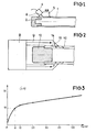
- La figure 1 représente, dans une vue en coupe, l'extrémité d'un crayon combustible sur laquelle on a placé un dispositif émetteur et récepteur d'ultra-sons pour la mise en oeuvre du procédé suivant l'invention.
- La figure 2 représente à plus grande échelle et dans une vue en coupe la zone voisine du bouchon d'un crayon combustible sur laquelle a été adapté un dispositif émetteur et récepteur d'ultra-sons permettant la mise en oeuvre du procédé suivant l'invention.
- La figure 3 représente les variations de l'atténuation des ondes de Lamb dans la gaine d'un crayon combustible, en fonction de la quantité d'eau résiduelle à l'intérieur du crayon combustible.
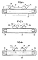
- La figure 4 représente, dans une vue en coupe, un crayon combustible sur lequel ont été montés deux dispositifs à ultra-sons, l'un émetteur, l'autre récepteur.
- La figure 5 représente, dans une vue en coupe, un crayon combustible sur lequel ont été montés deux dispositifs émetteur et récepteur d'ultra-sons pour la mise en oeuvre du procédé suivant l'invention.
- La figure 6 représente une variante du dispositif avec deux émetteurs récepteurs d'ultra-sons. On voit sur la figure 1 l'extrémité d'un crayon combustible comportant une
gaine 1 fermée par unbouchon 2 soudé sur l'extrémité de la gaine tubulaire 1, la gaine tubulaire renfermant des pastilles de combustible nucléaire non représentées et de l'hélium assurant une pressurisation convenable du crayon combustible.
- Figure 1 shows, in a sectional view, the end of a fuel rod on which is placed a device emitting and receiving ultrasound for the implementation of the method according to the invention.
- Figure 2 shows on a larger scale and in a sectional view the area near the cap of a fuel rod on which has been adapted a device emitting and receiving ultrasound allowing the implementation of the method according to the invention .
- FIG. 3 represents the variations in the attenuation of the Lamb waves in the cladding of a fuel rod, as a function of the amount of residual water inside the fuel rod.
- Figure 4 shows, in a sectional view, a fuel rod on which have been mounted two ultrasonic devices, one transmitter, the other receiver.
- FIG. 5 represents, in a sectional view, a fuel rod on which two ultrasonic transmitter and receiver devices have been mounted for implementing the method according to the invention.
- FIG. 6 represents a variant of the device with two ultrasonic transmitter receivers. We see in Figure 1 the end of a fuel rod having a
sheath 1 closed by aplug 2 welded to the end of thetubular sheath 1, the tubular sheath containing pellets of nuclear fuel not shown and helium ensuring proper pressurization of the fuel rod.
Le dispositif d'émission et de réception des ultra-sons comporte un émetteur-récepteur 4 et une cale en plexiglas 5 accolée par sa face 6 inclinée de 45° par rapport à l'axe du crayon combustible à la face d'émission et de réception du transducteur 4.The device for transmitting and receiving ultrasound comprises a transceiver 4 and a Plexiglas block 5 attached by its
La cale de plexiglas assure un bon couplage entre le transducteur et le tube de gainage 1 et pour cela présente un évidement cylindrique sur sa face d'appui en contact avec le tube de gainage 1.The Plexiglas wedge ensures good coupling between the transducer and the
Les ondes ultra-sonores émises par le transducteur 4 sont envoyées grâce à la cale de plexiglas dans le tube de gainage 1 avec un angle d'incidence voisin de 45° par rapport à l'axe du tube.The ultrasonic waves emitted by the transducer 4 are sent thanks to the Plexiglas wedge in the
De cette façon les ondes ultra-sonores émises dans la paroi latérale du tube de gainage 1 n'interfèrent pas avec le bouchon 2 et donnent naissance par réflexion sur la surface interne et la surface externe du tube 1 à des ondes de plaques ou ondes de Lamb qui se propagent suivant la direction axiale du tube dans toute la surface latérale de ce tube. Le mode préférentiel généralement engendré est le mode So.In this way the ultrasonic waves emitted in the side wall of the
Le transducteur 4 et la cale 5 sont choisis de façon à émettre et à recevoir de façon préférentielle un mode d'ondes de Lamb qui permet une propagation dans le tube avec une atténuation faible et des signaux parasites négligeables dans le cas d'un tube ne présentant pas de défaut et d'humidité.The transducer 4 and the shim 5 are chosen so as to emit and to receive in a preferential way a mode of waves of Lamb which allows a propagation in the tube with weak attenuation and negligible parasitic signals in the case of a tube does not showing no defect and humidity.
On voit sur la figure 2 une variante d'exécution de la pièce de liaison en plexiglas permettant d'engendrer dans la gaine du crayon combustible des ondes dont l'angle d'incidence est voisin de 45°, cette pièce entourant la surface externe de la gaine du crayon combustible à l'une de ses extrémités.We see in Figure 2 an alternative embodiment of the plexiglass connecting piece for generating in the fuel rod cladding waves whose angle of incidence is close to 45 °, this piece surrounding the external surface of the sheath of the fuel rod at one of its ends.
Dans le montage représenté à la figure 2, le dispositif émetteur et récepteur d'ultra-sons 8 est couplé à une pièce de liaison 9 dont la face de contact 11 entoure la surface externe du tube de gainage 10 sur sa partie proche du bouchon 12.In the assembly shown in FIG. 2, the ultrasonic transmitter and
Les ondes ultra-sonores réfléchies sur la face 14 de la cale en plexiglas 9 sont réfléchies vers la surface latérale du tube 10 pour pénétrer dans ce tube avec une incidence voisine de 45°. Les ondes réfléchies par les surfaces interne et externe du tube 10 donnent naissance à des ondes de Lamb se propageant dans la direction axiale du tube et ne subissent aucune réflexion due au bouchon 12 au cours de leur propagation vers l'extrémité opposée du tube de gainage.The ultrasonic waves reflected on the
Dans le cas des dispositifs représentés aux figures 1 et 2, l'émission d'ondes de Lamb et la propagation de ces ondes vers l'extrémité du tube de gainage opposée à l'extrémité représentée aux figures 1 et 2 donnent naissance à un écho lorsque ces ondes de Lamb sont réfléchies par le bouchon se trouvant à l'extrémité opposée au bouchon 2 ou au bouchon 12.In the case of the devices represented in FIGS. 1 and 2, the emission of Lamb waves and the propagation of these waves towards the end of the cladding tube opposite the end shown in FIGS. 1 and 2 give rise to a echo when these Lamb waves are reflected by the plug located at the end opposite to plug 2 or
Le dispositif émetteur-récepteur 4 ou 8 permet de recueillir le signal écho, d'enregistrer ce signal ét dé mesurer latténuation due au parcours dans le tube.The transmitter-
Dans le cas de tube de gainage de crayons combustibles neufs, l'atténuation est extrêmement faible dans tous les cas où le tube ne renferme aucune humidité, à part évidemment les cas où accidentellement le tube de gainage présente une fissure venant d'un défaut de fabrication et où la soudure entre le tube de gainage et le bouchon sur lequel a lieu la réflexion des ondes est défectueuse.In the case of a sheathing tube of new fuel rods, the attenuation is extremely low in all cases where the tube does not contain any moisture, except obviously the cases where accidentally the sheathing tube has a crack coming from a defect of manufacturing and where the solder between the cladding tube and the plug on which the reflection of the waves takes place is defective.
Dans ces cas particuliers, on peut avoir une idée de l'origine de l'atténuation du signal en analysant le signal reçu pour détecter la présence de signaux parasites.In these particular cases, one can get an idea of the origin of the signal attenuation by analyzing the received signal to detect the presence of spurious signals.
Si l'atténuation s'accompagne de la présence d'un signal parasite unique on est en présence d'une fissure et l'atténuation est due au moins partiellement à cette fissure.If the attenuation is accompanied by the presence of a single parasitic signal, there is a crack and the attenuation is due at least partially to this crack.
Si l'on n'enregistre pas la présence de signaux parasites, on est alors en présence d'un défaut de soudure qui est responsable de l'atténuation du signal écho.If the presence of spurious signals is not recorded, then there is a welding fault which is responsible for the attenuation of the echo signal.
Dans le cas de crayons combustibles neufs, ces défauts sont relativement rares et dans la quasi- totalité des cas l'atténuation du signal reçu est due à la présence de traces d'humidité dans le tube.In the case of new fuel rods, these defects are relatively rare and in almost all cases the attenuation of the received signal is due to the presence of traces of humidity in the tube.
Cette présence d'humidité dans le tube, sous forme de très fines gouttelettes accrochées à la paroi interne du tube de gainage provoque l'apparition d'une série de signaux parasites caractéristiques de la présence d'eau dans le tube de gainage.This presence of moisture in the tube, in the form of very fine droplets attached to the internal wall of the cladding tube causes the appearance of a series of parasitic signals characteristic of the presence of water in the cladding tube.
D'autre part l'atténuation du signal permet de connaître la quantité d'eau se trouvant dans le tube lorsqu'on a tracé une courbe telle que celle représentée à la figure 3. Une telle courbe est obtenue en effectuant des mesures d'atténuation sur des tubes de gainage étalon renfermant des quantités dosées d'eau et en les reportant sur un graphique tel que représenté à la figure 3.On the other hand, the attenuation of the signal makes it possible to know the quantity of water being in the tube when a curve such as that shown in FIG. 3 has been drawn. Such a curve is obtained by carrying out attenuation measurements on standard cladding tubes containing metered quantities of water and plotting them on a graph as shown in FIG. 3.
On voit sur cette figure 3 qu'il est possible de mesurer des quantités aussi faibles que 6 mg qui correspondraient à une atténuation de l'écho aisément mesurable, de l'ordre de 10 décibels.We see in this figure 3 that it is possible to measure quantities as low as 6 mg which would correspond to an easily measurable echo attenuation, of the order of 10 decibels.
Ce résultat se compare très favorablement avec le résultat des méthodes antérieures qui étaient limitées à une sensibilité relativement faible puisqu'on ne pouvait détecter que la présence de quantités d'eau de l'ordre de 50 mg représentant approximativement la quantité d'eau dans une goutte détectable par les méthodes ultra-sonores de l'art antérieur.This result compares very favorably with the result of previous methods which were limited to a relatively low sensitivity since it was only possible to detect the presence of amounts of water of the order of 50 mg representing approximately the amount of water in a drop detectable by the ultrasonic methods of the prior art.
En se reportant à la figure 4, on voit un crayon combustible comportant un tube de gainage 20 et deux bouchons d'extrémité 21 et 22 sur la surface latérale duquel ont été placés deux dispositifs pour l'émission et la réception d'ultra-sons 23 et 24 couplés à des cales en plexiglas 25 et 26 entourant la surface latérale du tube de gainage 20 de crayons combustibles.Referring to Figure 4, we see a fuel rod having a
Le dispositif 23, 25 est un dispositif émetteur d'ondes ultra-sonores et le dispositif 24, 26 est un dispositif récepteur de ces ondes après yp certain parcours de longueur 1 à l'intérieur de la paroi tubulaire de la gaine 20.The
La distance 1 entre les deux transducteurs est évidemment inférieure à la longueur du crayon combustible si bien qu'il est possible d'explorer toute la surface du crayon combustible en déplaçant l'ensemble de l'émetteur et du récepteur séparés par une longueur 1.The
On peut rendre solidaires l'émetteur et le récepteur d'ultra-sons à l'aide d'un bâti commun qui permet de maintenir l'écartement 1 de ces deux transducteurs.The transmitter and the receiver of ultrasound can be made integral with the aid of a common frame which makes it possible to maintain the
De la même façon que lors de l'utilisation des dispositifs représentés aux figures 1 et 2, on mesure l'atténuation des ondes de Lamb engendrées dans le tube par les ondes ultra-sonores incidentes avec un angle voisin de 45° par rapport à l'axe du tube, entre l'émetteur et le récepteur d'ultra-sons.In the same way as when using the devices represented in FIGS. 1 and 2, the attenuation of the Lamb waves generated in the tube by the incident ultrasonic waves is measured with an angle close to 45 ° relative to l 'axis of the tube, between the transmitter and receiver of ultrasound.
Dans le cas où l'on détecte, pour une position de l'émetteur et du récepteur une atténuation des ondes de Lamb, on peut en déduire la présence d'humidité sur la paroi latérale interne du tube de gainage entre l'émetteur et le récepteur d'ultra-sons.In the event that attenuation of the Lamb waves is detected for a position of the transmitter and of the receiver, it can be deduced therefrom the presence of moisture on the internal lateral wall of the cladding tube between the transmitter and the ultrasonic receiver.
En déplaçant les dispositifs sur la longueur du crayon combustible, il est facile de comparer les résultats obtenus sur les différentes zones du crayon exploré et de pouvoir comparer ces résultats pour détecter une atténuation anormale des ondes de Lamb due à la présence d'humidité dans le tube.By moving the devices along the length of the fuel rod, it is easy to compare the results obtained on the different areas of the explored pencil and to be able to compare these results to detect an abnormal attenuation of the Lamb waves due to the presence of moisture in the tube.
Ce dispositif et cette méthode d'examen sont particulièrement intéressants lorsque l'on recherche des crayons défectueux pour procéder à leur dégainage et à leur remplacement. En effet, la comparaison des résultats obtenus sur les différentes zones du crayon combustible est immédiate et permet de déterminer très rapidement une anomalie sur la gaine du crayon combustible.This device and this examination method are particularly advantageous when looking for defective pencils in order to draw them out and replace them. Indeed, the comparison of the results obtained on the different zones of the fuel rod is immediate and makes it possible to very quickly determine an anomaly on the sheath of the fuel rod.
En se reportant à la figure 5, on voit un nouveau mode de réalisation d'un dispositif permettant la mise en oeuvre du procédé suivant l'invention où le tube de gainage 30 d'un crayon combustible fermé par deux bouchons 31 et 32 et parcouru par des ondes ultra-sonores dirigées suivant des directions de propagation opposées grâce à deux émetteurs-récepteurs d'ultra-sons 33 et 34 associés à des cales en plexiglas 35 et 36, entourant la surface externe du tube et émettant des ondes ultra-sonores dirigées approximativement à 45° par rapport à l'axe du tube dans des directions symétriques par rapport à un plan transversal du tube.Referring to Figure 5, we see a new embodiment of a device for implementing the method according to the invention where the
Ces ondes de Lamb se propageant dans des directions opposées et simultanément sont réfléchies par les bouchons 31 et 32 et reçues en retour par les émetteurs-récepteurs 33 et 34 respectivement.These Lamb waves propagating in opposite directions and simultaneously are reflected by the
De cette façon on enregistre simultanément, grâce à un oscillographe à double canal les signaux correspondant à chacune des deux demi-gaines dans lesquelles se propagent les ultra-sons, les dispositifs émetteurs-récepteurs étant disposés approximativement au milieu du tube 30.In this way we record simultaneously, thanks to a dual-channel oscillograph, the signals corresponding to each of the two half-sheaths in which the ultrasound propagates, the transceiver devices being arranged approximately in the middle of the
De cette façon on peut comparer directement les signaux d'écho obtenus par réflexion sur les bouchons 31 et 32 en amenant en coïncidence ces signaux d'écho de façon à comparer leurs amplitudes.In this way it is possible to directly compare the echo signals obtained by reflection on the
Il est ainsi extrêmement facile de détecter la présence éventuelle d'eau et de déterminer la demi-gaine affectée par l'humidité.It is thus extremely easy to detect the possible presence of water and to determine the half-sheath affected by humidity.
Cette méthode évite ainsi l'utilisation d'un étalonnage préalable puisqu'elle utilise la comparaison directe des atténuations dans les deux parties de la gaine du crayon combustible dans lesquelles se propagent simultanément les ondes de Lamb.This method thus avoids the use of a preliminary calibration since it uses the direct comparison of the attenuations in the two parts of the cladding of the fuel rod in which the Lamb waves propagate simultaneously.
D'autre part cette méthode a l'avantage d'éliminer l'influence des caractéristiques métallurgiques ou mécaniques du matériau constituant la gaine puisque la comparaison est faite sur deux parties d'un même tube métallique.On the other hand this method has the advantage of eliminating the influence of the metallurgical or mechanical characteristics of the material constituting the sheath since the comparison is made on two parts of the same metal tube.
Le positionnement précis des capteurs est assuré en observant les signaux d'écho obtenus pour chacun de ces deux capteurs et en déplaçant ces capteurs de façon à amener en coïncidence les signaux d'écho, ce qui permet la comparaison des amplitudes.The precise positioning of the sensors is ensured by observing the echo signals obtained for each of these two sensors and by moving these sensors so as to bring the echo signals into coincidence, which allows the comparison of the amplitudes.
Mais il est possible également de perfectionner encore le procédé de contrôle en utilisant le dispositif représenté à la figure 6.However, it is also possible to further improve the control process by using the device shown in FIG. 6.
En effet, si l'on intervertit la position des émetteurs-récepteurs 33 et 34 pour obtenir la disposition représentée à la figure 6, les ondes émises par le transducteur 34 dont le parcours dans la gaine tubulaire commence au point A', vont parcourir le tube de gainage suivant le trajet A'BB'A.In fact, if the position of the
Simultanément, les ondes émises par l'émetteur récepteur 33 vont parcourir le trajet AB'BA'.Simultaneously, the waves emitted by the
Chacun de ces parcours représente un trajet total à l'intérieur du tube de gainage identique et comporte des réflexions sur les bouchons 31 et 32, si bien qu'on s'affranchit ainsi des perturbations dues aux hétérogénéités éventuelles du matériau du tube et aux hétérogénéités des soudures des deux bouchons.Each of these paths represents a total path inside the identical cladding tube and includes reflections on the
On élimine également de ce fait les écarts qui seraient dus à des différences dans la forme des deux bouchons.This also eliminates the differences that would be due to differences in the shape of the two plugs.
En effet, si l'on enregistre sur un oscillographe, simultanément les signaux émis et reçus par les deux émetteurs-récepteurs, dans le cas où le tube ne contient aucune trace d'eau, les deux enregistrements sont strictement identiques puisque les deux voies de parcours sont également identiques.In fact, if the signals transmitted and received by the two transceivers are recorded simultaneously on an oscillograph, in the case where the tube contains no trace of water, the two recordings are strictly identical since the two channels of routes are also identical.
Par contre, dans le cas où il existe des traces d'eau sur la surface intérieure du tube de gainage, les signaux parasites dus à cette eau se trouvent décalés par rapport aux signaux d'écho sur l'un et l'autre enregistrement. En même temps, les signaux d'écho sont atténués ce qui permet, comme précédemment, de déterminer les quantités d'eau sur la surface interne du tube de gainage. On obtient évidemment deux valeurs de l'atténuation qui doivent être identiques pour l'une et l'autre voie de mesure.On the other hand, in the case where there are traces of water on the interior surface of the cladding tube, the spurious signals due to this water are offset with respect to the echo signals on both recording. At the same time, the echo signals are attenuated, which makes it possible, as before, to determine the amounts of water on the internal surface of the cladding tube. Obviously, two attenuation values are obtained which must be identical for both measurement channels.
Dans tous les cas, on voit que le procédé suivant l'invention permet de détecter et de déterminer quantitativement de très faibles traces d'eau à l'intérieur d'un tube de gainage d'un crayon combustible neuf par une mesure utilisant la propagation d'ondes ultra-sonores dans la paroi latérale du tube.In all cases, it can be seen that the method according to the invention makes it possible to detect and quantitatively determine very small traces of water inside a cladding tube of a new combustible rod by a measurement using propagation. ultrasonic waves in the side wall of the tube.
On voit également que le procédé suivant l'invention permet de distinguer facilement les défauts physiques du crayon combustible (fissures ou défauts de soudage des bouchons) des traces d'humidité, en observant les signaux captés après un certain parcours dans la paroi du tube.It can also be seen that the method according to the invention makes it possible to easily distinguish the physical defects of the fuel rod (cracks or welding defects in the plugs) from traces of humidity, by observing the signals picked up after a certain course in the wall of the tube.
Le procédé suivant l'invention permet évidemment d'éliminer également les tubes de gainage qui comportent des défauts tels que fissures ou défauts de soudure des bouchons.The method according to the invention obviously makes it possible also to eliminate the cladding tubes which have defects such as cracks or welding defects in the plugs.
Enfin, des mesures comparatives sur différentes portions du tube de gainage permettent des déterminations très rapides de la présence d'humidité sur ces portions de tube.Finally, comparative measurements on different portions of the cladding tube allow very rapid determinations of the presence of moisture on these tube portions.
Mais l'invention ne se limite pas aux modes de réalisation qui viennent d'être décrits, elle en comporte au contraire toutes les variantes et il est possible d'imaginer des modifications de points de détail sans pour autant sortir du cadre de l'invention.However, the invention is not limited to the embodiments which have just been described, on the contrary it includes all the variants thereof and it is possible to imagine modifications of details without departing from the scope of the invention .
C'est ainsi qu'il est possible d'utiliser des cales en un matériau différent du plexiglas, l'angle d'incidence optimal des ondes pouvant cependant varier en fonction du matériau choisi.This is how it is possible to use shims made of a material different from Plexiglas, the optimum angle of incidence of the waves being able to vary depending on the material chosen.
La fréquence des ondes émises peut varier dans une large mesure, cependant les essais de la demanderesse ont montré que les fréquences optimales de ces ondes sont inférieures à 1 MHz.The frequency of the waves emitted can vary to a large extent, however the applicant's tests have shown that the optimal frequencies of these waves are less than 1 MHz.
On a décrit quelques dispositions des émetteurs ou des émetteurs-récepteurs sur la surface latérale du tube de gainage ; cependant on peut imaginer d'autres dispositifs et d'autres types de mesures comparatives que celles qui ont été décrites, en imaginant des parcours des ondes de Lamb dans la paroi du tube de gainage plus ou moins complexes, avec ou sans réflexion sur les bouchons d'extrémité du crayon combustible ou sur d'autres dispositifs de réflexion.A few arrangements of the transmitters or transceivers have been described on the lateral surface of the cladding tube; however one can imagine other devices and other types of comparative measurements than those which have been described, by imagining paths of Lamb waves in the wall of the sheathing tube more or less complex, with or without reflection on the plugs end of the fuel rod or on other reflecting devices.
De plus, le procédé suivant l'invention et les dispositifs correspondants sont applicables non seulement dans le cas des crayons combustibles pour les assemblages destinés à être placés dans le coeur des réacteurs nucléaires à eau pressurisée mais également à tout type de crayons combustibles comportant un tube de gainage fermé de façon étanche par des bouchons.In addition, the method according to the invention and the corresponding devices are applicable not only in the case of fuel rods for assemblies intended to be placed in the core of nuclear pressurized water reactors but also to any type of fuel rods comprising a tube sheathing tightly closed with plugs.
Enfin, les types de capteurs décrits aux figures 4 à 6 peuvent être avantageusement remplacés par une structure de capteur annulaire entourant entièrement le tube, comme cela est montré à la figure 2,Finally, the types of sensors described in FIGS. 4 to 6 can advantageously be replaced by an annular sensor structure completely surrounding the tube, as shown in FIG. 2,
Claims (8)
Applications Claiming Priority (2)
| Application Number | Priority Date | Filing Date | Title |
|---|---|---|---|
| FR7909984A FR2454675A1 (en) | 1979-04-20 | 1979-04-20 | METHOD FOR CONTROLLING FUEL PENCILS FOR ASSEMBLIES FOR NUCLEAR REACTOR AND DEVICE THEREOF |
| FR7909984 | 1979-04-20 |
Publications (2)
| Publication Number | Publication Date |
|---|---|
| EP0018290A1 EP0018290A1 (en) | 1980-10-29 |
| EP0018290B1 true EP0018290B1 (en) | 1982-11-03 |
Family
ID=9224527
Family Applications (1)
| Application Number | Title | Priority Date | Filing Date |
|---|---|---|---|
| EP80400526A Expired EP0018290B1 (en) | 1979-04-20 | 1980-04-18 | Method and apparatus for the control of fuel rods used in nuclear reactor assemblies |
Country Status (7)
| Country | Link |
|---|---|
| US (1) | US4366711A (en) |
| EP (1) | EP0018290B1 (en) |
| JP (1) | JPS56650A (en) |
| DE (1) | DE3061029D1 (en) |
| ES (1) | ES490687A0 (en) |
| FR (1) | FR2454675A1 (en) |
| ZA (1) | ZA802361B (en) |
Families Citing this family (18)
| Publication number | Priority date | Publication date | Assignee | Title |
|---|---|---|---|---|
| FR2493025B1 (en) * | 1980-10-24 | 1986-04-18 | Framatome Sa | METHOD AND DEVICE FOR DETECTING DEFECTIVE FUEL ELEMENTS IN A FUEL ASSEMBLY FOR A NUCLEAR REACTOR |
| DE3116978C2 (en) * | 1981-04-29 | 1986-06-12 | Brown Boveri Reaktor GmbH, 6800 Mannheim | Device for finding defective fuel rod cladding tubes in water-cooled nuclear reactors |
| DE3149362C2 (en) * | 1981-12-12 | 1983-10-27 | Brown Boveri Reaktor GmbH, 6800 Mannheim | Procedure for finding defective fuel rod cladding tubes with the help of ultrasound |
| GB2124764B (en) * | 1982-08-03 | 1986-01-08 | Atomic Energy Authority Uk | Ice detector |
| FR2538155B1 (en) * | 1982-12-17 | 1988-08-12 | Fragema Framatome & Cogema | METHOD AND DEVICE FOR DETECTING DEFECTIVE FUEL ELEMENTS USING ULTRASONIC ABSORPTION |
| FR2642560B1 (en) * | 1989-01-30 | 1991-05-17 | Framatome Sa | METHOD AND DEVICE FOR ULTRASONIC DETECTION OF NON-WATERTIGHT FUEL PENCILS IN A FUEL ASSEMBLY |
| ES2075734T3 (en) * | 1992-03-26 | 1995-10-01 | Siemens Power Corp | METHOD AND APPARATUS FOR DETECTING DAMAGED FUEL RODS THROUGH THE USE OF ATTENUATION OF THE ACOUSTIC ENERGY WAVE. |
| US5790617A (en) * | 1992-03-26 | 1998-08-04 | Siemens Power Corporation | Method and apparatus for detection of failed fuel rods by use of acoustic energy frequency attenuation |
| TW444205B (en) * | 1998-02-09 | 2001-07-01 | Siemens Power Corp | Method for the inspection of nuclear fuel rod for fretting and wear within a nuclear fuel assembly |
| EP0936630A1 (en) * | 1998-02-10 | 1999-08-18 | Siemens Power Corporation | Detection of nuclear fuel rod failure |
| US6923067B2 (en) | 1999-03-19 | 2005-08-02 | Betriebsforschungsinstitut Vdeh Institut Fur Angewandte Forschung Gmbh | Defect type classifying method |
| US20040206181A1 (en) * | 1999-03-22 | 2004-10-21 | Betriebsforschungsinstitut Vdeh Institut Fur Angewandte Forschung Gmbh | Defect type classifying method |
| KR101222012B1 (en) * | 2011-07-08 | 2013-01-14 | 한전원자력연료 주식회사 | Measuring device for the fuel rod outside diameter of nuclear fuel assembly |
| DE102014118623B3 (en) * | 2014-12-15 | 2016-04-28 | Areva Gmbh | Apparatus and method for performing a leak test on fuel rod capsules |
| US10234432B2 (en) * | 2016-08-04 | 2019-03-19 | The Boeing Company | Device and method to detect cracks in the countersink of a fastener |
| CN106770642A (en) * | 2016-11-15 | 2017-05-31 | 中国科学院苏州生物医学工程技术研究所 | Device for measuring moisture and method, Lamb wave sensor and gas humidity measuring method |
| CN106814135B (en) * | 2017-01-26 | 2019-03-15 | 吉林大学 | The phased array supersonic automatic testing method of electric arc plug welds |
| JP6746048B1 (en) * | 2020-03-03 | 2020-08-26 | 三菱電機株式会社 | Humidity sensor |
Family Cites Families (9)
| Publication number | Priority date | Publication date | Assignee | Title |
|---|---|---|---|---|
| US2912854A (en) * | 1955-05-27 | 1959-11-17 | Gen Motors Corp | Ultrasonic surface testing device |
| US3233449A (en) * | 1960-10-06 | 1966-02-08 | Republic Steel Corp | Method and apparatus for ultrasonic testing of pipe |
| US3512400A (en) * | 1967-04-13 | 1970-05-19 | Panametrics | Ultrasonic testing method |
| DE2314650C3 (en) * | 1973-03-23 | 1978-10-12 | Kraftwerk Union Ag, 4330 Muelheim | Method and device for finding defective fuel rods |
| DE2642156A1 (en) * | 1976-09-20 | 1978-03-23 | Kraftwerk Union Ag | PROCEDURE AND EQUIPMENT FOR DETECTING DEFECTIVE FUEL RODS |
| DE2528422C3 (en) * | 1975-06-26 | 1979-06-13 | Babcock-Brown Boveri Reaktor Gmbh, 6800 Mannheim | Method for localizing leaky casing tubes of fuel rods of a nuclear reactor fuel assembly and device for carrying out the method |
| FR2325932A1 (en) * | 1975-09-23 | 1977-04-22 | Tech Ind Mecanique Centre | SUPERFICIAL ULTRA-SOUND EXAMINATION PROCESS AND DEVICE |
| JPS5298893A (en) * | 1976-02-11 | 1977-08-19 | Westinghouse Electric Corp | Method of sensing and searching defective fuel element in reactor |
| DE2605962C2 (en) * | 1976-02-14 | 1982-05-06 | Brown Boveri Reaktor GmbH, 6800 Mannheim | Device for localizing defective fuel rod cladding tubes of a complete fuel assembly |
-
1979
- 1979-04-20 FR FR7909984A patent/FR2454675A1/en active Granted
-
1980
- 1980-04-17 JP JP5108480A patent/JPS56650A/en active Pending
- 1980-04-17 US US06/142,370 patent/US4366711A/en not_active Expired - Lifetime
- 1980-04-18 DE DE8080400526T patent/DE3061029D1/en not_active Expired
- 1980-04-18 EP EP80400526A patent/EP0018290B1/en not_active Expired
- 1980-04-18 ES ES490687A patent/ES490687A0/en active Granted
- 1980-04-21 ZA ZA00802361A patent/ZA802361B/en unknown
Also Published As
| Publication number | Publication date |
|---|---|
| ZA802361B (en) | 1981-04-29 |
| EP0018290A1 (en) | 1980-10-29 |
| ES8301552A1 (en) | 1982-12-01 |
| US4366711A (en) | 1983-01-04 |
| ES490687A0 (en) | 1982-12-01 |
| DE3061029D1 (en) | 1982-12-09 |
| JPS56650A (en) | 1981-01-07 |
| FR2454675B1 (en) | 1984-10-05 |
| FR2454675A1 (en) | 1980-11-14 |
Similar Documents
| Publication | Publication Date | Title |
|---|---|---|
| EP0018290B1 (en) | Method and apparatus for the control of fuel rods used in nuclear reactor assemblies | |
| EP0493146B1 (en) | Apparatus for non-destructive ultrasonic testing of elongated elements with an approximately constant section | |
| US8201454B2 (en) | Pipeline inspection apparatus and method | |
| EP0051016B1 (en) | Method and device for detecting defective fuel elements in a nuclear reactor fuel assembly | |
| FR2558960A1 (en) | METHOD FOR INSPECTING WELDS BETWEEN TUBES AND TUBES PLATES | |
| JPS5914187B2 (en) | Spot welding inspection equipment | |
| EP0115231B1 (en) | Method and device for detecting defective fuel elements | |
| EP1271097A2 (en) | Method for inspecting clad pipe | |
| WO2013189885A1 (en) | Non-destructive ultrasound testing of structures made of composite material | |
| FR2716714A1 (en) | Method and device for ultrasonic testing of facets on the inner surface of the wall of a sheath. | |
| EP2381251B1 (en) | Device for and method of non-destructively detecting thickness anomalies of a tube wall | |
| KR20030081533A (en) | High-frequency ultrasound measurement of partial layer thickness of thin-walled tubes by a contact method | |
| WO2013083603A1 (en) | Acoustic sensor for measuring a linear movement of an internal structure of a nuclear reactor | |
| EP0381551B1 (en) | Method and device for detecting leaking fuel rods in fuel assemblies by ultrasonic means | |
| EP2166306B1 (en) | Device and method for controlling the dimensions of a fuel rod cladding tube of a nuclear fuel control cluster in a nuclear reactor | |
| FR2717578A1 (en) | Device for non-destructive ultrasonic testing of a cylindrical wall accessible by an annular passage of small width. | |
| BG99112A (en) | Method and instrument for establishing faulty fuel stems by using acoustic energy frequency attenuation | |
| KR830002647B1 (en) | Test method for new fuel rods for nuclear fuel assemblies | |
| FR2523723A1 (en) | Detecting defective fuel rod can - by change in natural frequency caused by loss of internal gas pressure | |
| FR2741717A1 (en) | COMPOSITE PROBE APPARATUS | |
| FR2791137A1 (en) | Automatic ultrasonic testing method for use with elongated elements, such as tubes or bars, for detection of circumferential or longitudinal defects has an array of only two probes | |
| WO2022138361A1 (en) | Optical sensor and physical quantity measurement device | |
| WO2023061957A1 (en) | Ultrasound probe for inspecting a component at a temperature above 150°c and associated inspecting method | |
| FR2466771A1 (en) | Pipe integrity testing using two ultrasonic sensors - acting as transmitter and receiver and moved along outer surface at set distance apart | |
| FR2466082A1 (en) | METHOD OF ACOUSTICALLY AND ULTRASONICALLY DETECTING COMBUSTIBLE ASSEMBLIES OF A NUCLEAR REACTOR WHICH HAVE BEEN DEFECTIVE IN SERVICE AND CORRESPONDING DETECTION DEVICE |
Legal Events
| Date | Code | Title | Description |
|---|---|---|---|
| PUAI | Public reference made under article 153(3) epc to a published international application that has entered the european phase |
Free format text: ORIGINAL CODE: 0009012 |
|
| AK | Designated contracting states |
Designated state(s): BE DE GB IT SE |
|
| 17P | Request for examination filed |
Effective date: 19800930 |
|
| ITF | It: translation for a ep patent filed |
Owner name: JACOBACCI & PERANI S.P.A. |
|
| GRAA | (expected) grant |
Free format text: ORIGINAL CODE: 0009210 |
|
| AK | Designated contracting states |
Designated state(s): BE DE GB IT SE |
|
| REF | Corresponds to: |
Ref document number: 3061029 Country of ref document: DE Date of ref document: 19821209 |
|
| ITTA | It: last paid annual fee | ||
| EAL | Se: european patent in force in sweden |
Ref document number: 80400526.2 |
|
| PGFP | Annual fee paid to national office [announced via postgrant information from national office to epo] |
Ref country code: GB Payment date: 19960412 Year of fee payment: 17 |
|
| PGFP | Annual fee paid to national office [announced via postgrant information from national office to epo] |
Ref country code: SE Payment date: 19960418 Year of fee payment: 17 |
|
| PGFP | Annual fee paid to national office [announced via postgrant information from national office to epo] |
Ref country code: BE Payment date: 19960424 Year of fee payment: 17 |
|
| PGFP | Annual fee paid to national office [announced via postgrant information from national office to epo] |
Ref country code: DE Payment date: 19960628 Year of fee payment: 17 |
|
| PG25 | Lapsed in a contracting state [announced via postgrant information from national office to epo] |
Ref country code: GB Effective date: 19970418 |
|
| PG25 | Lapsed in a contracting state [announced via postgrant information from national office to epo] |
Ref country code: SE Effective date: 19970419 |
|
| PG25 | Lapsed in a contracting state [announced via postgrant information from national office to epo] |
Ref country code: BE Effective date: 19970430 |
|
| BERE | Be: lapsed |
Owner name: FRAMATOME Effective date: 19970430 |
|
| GBPC | Gb: european patent ceased through non-payment of renewal fee |
Effective date: 19970418 |
|
| PG25 | Lapsed in a contracting state [announced via postgrant information from national office to epo] |
Ref country code: DE Free format text: LAPSE BECAUSE OF NON-PAYMENT OF DUE FEES Effective date: 19980101 |
|
| EUG | Se: european patent has lapsed |
Ref document number: 80400526.2 |
|
| PLBE | No opposition filed within time limit |
Free format text: ORIGINAL CODE: 0009261 |
|
| STAA | Information on the status of an ep patent application or granted ep patent |
Free format text: STATUS: NO OPPOSITION FILED WITHIN TIME LIMIT |