EP0460643B1 - Circuit de secours pour, par exemple, unité de commande numérique - Google Patents
Circuit de secours pour, par exemple, unité de commande numérique Download PDFInfo
- Publication number
- EP0460643B1 EP0460643B1 EP91109197A EP91109197A EP0460643B1 EP 0460643 B1 EP0460643 B1 EP 0460643B1 EP 91109197 A EP91109197 A EP 91109197A EP 91109197 A EP91109197 A EP 91109197A EP 0460643 B1 EP0460643 B1 EP 0460643B1
- Authority
- EP
- European Patent Office
- Prior art keywords
- circuit
- signal
- unit
- emergency stop
- clock signal
- Prior art date
- Legal status (The legal status is an assumption and is not a legal conclusion. Google has not performed a legal analysis and makes no representation as to the accuracy of the status listed.)
- Expired - Lifetime
Links
Images


Classifications
-
- H—ELECTRICITY
- H02—GENERATION; CONVERSION OR DISTRIBUTION OF ELECTRIC POWER
- H02H—EMERGENCY PROTECTIVE CIRCUIT ARRANGEMENTS
- H02H1/00—Details of emergency protective circuit arrangements
- H02H1/0061—Details of emergency protective circuit arrangements concerning transmission of signals
- H02H1/0084—Details of emergency protective circuit arrangements concerning transmission of signals by means of pilot wires or a telephone network; watching of these wires
-
- H—ELECTRICITY
- H02—GENERATION; CONVERSION OR DISTRIBUTION OF ELECTRIC POWER
- H02H—EMERGENCY PROTECTIVE CIRCUIT ARRANGEMENTS
- H02H7/00—Emergency protective circuit arrangements specially adapted for specific types of electric machines or apparatus or for sectionalised protection of cable or line systems, and effecting automatic switching in the event of an undesired change from normal working conditions
- H02H7/005—Emergency protective circuit arrangements specially adapted for specific types of electric machines or apparatus or for sectionalised protection of cable or line systems, and effecting automatic switching in the event of an undesired change from normal working conditions for remote controlled apparatus; for lines connecting such apparatus
Definitions
- the invention relates to a fault detection or alarm system for use with units which are connected by a signal cable, comprising a first unit, the first unit including an oscillator for generating a clock signal and a signal transmission circuit for transmitting the clock signal to the signal cable; and at least one second unit including signal determination circuit means connected to the signal cable for detecting when the clock signal is not included in the signal received from the cable and generating a fault signal in response to the absence of the clock signal.
- fault detection or alarm system is capable of reliably performing a fault detection for emergency action such as the stoppage of a controlled device, despite loss of electrical communication or other problems. Also, it is of interest to use such a fault detection or alarm system in connection with a numerically controlled machine tool.
- a fault detection or alarm system of the type specified above is known from the publication EP-A-0 066 737 where a two-wire circuit is provided comprising first and second lines which extend across detectors which may be provided as fire detectors.
- the detectors are provided as shunts with respect to the two-wire circuit.
- a monitoring shunt circuit is provided by means of which information is supplied to a control centre by sending monitoring pulses as signals that the two-wire circuit is continuously in order.
- the detector is formed by detecting a shunt in which by means of a contact a resistor is shunted pulse-wise to the two-wire circuit.
- the control of the respective contact is carried out by means of a pulse generator which in turn is controlled by a sensor.
- the sensor starts the operation of the respective pulse generator if the sensor detects a fire.
- the contact is actuated by pulses and thereby effects a pulse-wise increase of the closed-circuit current flowing through the two-wire circuit.
- a closed-circuit current is mainly determined by the current consumption of the sensor connected in a shunt of the two-wire circuit and additionally by the current consumption of the monitoring shunt circuit.
- This monitoring shunt circuit comprises a pulse generator which controls a contact which is connected to the two-wire circuit. As long as no interruption occurs in this two-wire circuit, the pulse generator of the monitoring shunt circuit is supplied with current and therefore permanently operates its contact in a pulsed manner.
- the respective pulse generator is of the type which is programmed to output an individual pulse code.
- the amplitude of the monitoring pulses supplied by the monitoring shunt circuit is considerably smaller than the amplitude of the pulse code supplied by the respective pulse generator associated with the respective sensor.
- the control centre can evaluate both the monitoring pulses and the pulse codes of the respective sensor.
- a first threshold trigger is provided which is adjusted that it switches through the detected value pulses received from the pulse generator of a sensor in the form of pulse codes, whereas it blocks the monitoring pulses generated by the pulse generator, using the signals of different amplitude.
- a second threshold trigger is provided which has a considerably lower threshold value so that it switches through both the monitoring pulses and the detected value pulses.
- the first threshold trigger switches through the pulses of the pulse code which are then evaluated in an evaluating circuit connected thereto and are converted into the display of an address in a display unit.
- a numerical control unit includes a numerical operation section and a plurality of servo amplifiers provided for individual axes, which are connected by a signal cable. Signals transferred through this signal cable include command signals and emergency stop signals from the numerical operation section to the servo amplifiers, feedback signals from the servo amplifiers to the numerical operation section, and signals concerned with diagnostics and servo control adjustments.
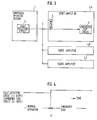
- Fig. 3 is a block circuit diagram of a known emergency stop device for a numerical control unit and an associated machine tool
- Fig. 4 is a timing chart for the circuit diagram shown in Fig. 3.
- the numeral 1 indicates a numerical operation section.
- a fault detection circuit provided in the numerical operation section 1.
- An emergency stop signal cable 3 is connected to the fault detection circuit 2, and servo amplifiers 4A to 4C are connected to the emergency stop signal cable 3.
- Pull-up resistors 5 are provided in the servo amplifiers 4A to 4C and connected to the emergency stop signal cable 3.
- Emergency stop circuits 6 are provided in each servo amplifier.
- the fault detection circuit 2 in the numerical operation section 1 detects an emergency stop input from outside the numerical control unit in addition to internal faults within the unit.
- the fault detection circuit 2 transmits a "low” signal to the emergency stop signal cable 3 when the operation is normal, and a "high” signal upon detection of any fault.
- the emergency stop circuits 6 When the signal transmitted through the emergency stop signal cable 3 is "low", the emergency stop circuits 6 put the servo amplifiers 4A to 4C into a normal operation state as shown in Fig. 4. When that signal goes "high” at time tl, the emergency stop circuits 6 put the servo amplifiers 4A to 4C into an emergency stop state. That is, either the input of an external emergency stop command or the detection of any fault within the unit results in an emergency stop state.
- Breakage of the emergency stop signal cable 3 itself is one of the failures which may occur.
- the pull-up resistor 5 switches the input to the emergency stop circuit 6 to "high" to start the emergency stop state, thereby ensuring fail-safe operation.
- the known circuit is designed to detect a signal transmitted from a fault detection circuit 2 through an emergency stop signal cable 3. Therefore, when the emergency stop signal is made "low” due to an accidental contact of the emergency stop signal cable 3 with a common or ground point or the like, or when there is a faulty circuit in any of the servo amplifiers 4A to 4C, the emergency stop state cannot be entered if an attempt is made to effect an emergency stop from the numerical operation section 1, and thus fail-safe operation cannot be achieved under such circumstances.
- an object of the present invention to overcome the disadvantages in the prior art by providing a circuit which allows an emergency stop function to operate on a fail-safe basis even if a fault occurs in the emergency stop signal cable or in any of the controlled units.
- the object underlying the present invention is solved by a fault detection or alarm system as specified above which is characterized in that the signal transmission circuit is arranged for operating on the clock signal from the oscillator and an output signal from a fault detection circuit located in the first unit and for transmitting the clock signal to the signal cable when the fault detection circuit does not detect any fault and for inhibiting transmission of the clock signal to the signal cable when the fault detection circuit detects a fault.
- the signal determination circuit means include a first circuit for generating a signal in response to leading edges of the clock signal.
- a specific embodiment of the system according to the invention includes a delay circuit coupled to an output of the first circuit and inverter means coupled to an output of the delay circuit.
- the signal determination circuit means comprise a retriggerable stable multivibrator circuit.
- a still further embodiment of the system according to the invention includes an emergency stop circuit for stopping the operation of the at least one second unit, coupled to an output of the signal determination circuit means.
- the first unit comprises a control circuit for the at least one second unit.
- the first unit comprises a numerical control unit and the at least one second unit comprises at least one servo amplifier.
- the signal transmission circuit is an OR circuit combining the clock signal and the output of the fault detection circuit.
- Fig. 1 is a block diagram of an embodiment of the present invention and Fig. 2 is a timing chart therefor, wherein parts similar to those in the prior art circuit are designated by the same reference characters.
- the numeral 11 indicates an oscillator.
- An OR circuit 12 is connected to the oscillator 11 and to a fault detection circuit 2.
- These units 2, 11 and 12 constitute a signal detection circuit, the output side of which is connected to an emergency stop signal cable 3.
- An edge detection circuit 13 is connected to the emergency stop signal cable 3 for generating a pulse upon receipt of a leading edge of an input signal.
- a primary delay circuit 14 is connected to the edge detection circuit 13, and an inverting circuit 15 is connected to the primary delay circuit 14, the output side of which is connected to the emergency stop circuit 6.
- the edge detection circuit 13, the primary delay circuit 14 and the inverting circuit 15 constitute a signal determination circuit.
- the oscillator 11 continuously outputs a clock signal at predetermined intervals, both during normal operation and in an emergency stop state.
- the output of the OR circuit 12 is a clock signal as shown in Fig. 2c.
- This signal is input to the edge detection circuit 13 through the emergency stop signal cable 3.
- the edge detection circuit 13 outputs a pulse as shown in Fig. 2d in accordance with the leading edge of the input signal.
- the primary delay circuit 14 outputs that pulse input with an appropriate time constant, and if there is a pulse input, keeps the output "high” (see Fig. 2e).
- This signal is inverted by the inverting circuit 15 and its output, i. e. the input of the emergency stop circuit 6, is set “low” as shown in Fig. 2f to cancel the emergency stop.
- the OR circuit 12 employed as a signal detection circuit for synthesizing the emergency stop signal in the above embodiment may be replaced by a switch or a gate which has a similar function.
- edge detection circuit 13, the primary delay circuit 14 and the inverting circuit 15 used as a signal determination circuit for determining the presence or absence of the clock signal may be replaced by a retriggerable stable multivibrator or the like to provide a similar facility.
- the unbalanced connection type circuit for generating the emergency stop signal may be of a balanced type.
- the present embodiment is applicable not only to the transmission of an electrical signal through the emergency stop signal cable 3 but also to the detection using an optical signal.
- the determination made depending on whether the clock signal is present or absent is extremely significant.
- the invention achieves an emergency fault detection/alarm circuit which interprets a transmitted signal to be an emergency stop signal when the signal transmitted does not include a clock signal. Therefore, when maintained “high” or “low” due to a signal cable or controlled element fault, the signal is interpreted as an emergency stop signal, allowing the emergency stop function to operate on a fail-safe basis.
Claims (8)
- Système de détection d'erreurs ou système d'alarme, destiné à être utilisé avec des unités (1, 4A, 4B, 4C) qui sont raccordées par un câble à signaux (3), comprenant :- une première unité (1), la première unité (1) comprenant un oscillateur (11) pour produire un signal d'horloge, et un circuit de transmission de signaux (12) pour transmettre le signal d'horloge vers le câble à signaux (3) ; et- au moins une seconde unité (4A, 4B, 4C) comprenant un circuit de détermination de signaux (13, 14, 15) raccordé au câble à signaux (3) pour détecter lorsque le signal d'horloge n'est pas inclus dans les signaux reçus depuis le câble (3) et produire un signal de défaut en réponse à l'absence du signal d'horloge,caractérisé en ce que le circuit de transmission de signaux (12) est agencé pour fonctionner sur le signal d'horloge provenant de l'oscillateur (11) et sur un signal de sortie provenant d'un circuit de détection de défauts (2) situé dans la première unité (1), et pour transmettre le signal d'horloge vers le câble à signaux (3) lorsque le circuit de détection de défauts (2) ne détecte aucun défaut, et pour inhiber la transmission du signal d'horloge vers le câble à signaux (3) lorsque le circuit de détection de défauts (2) détecte un défaut.
- Système selon la revendication 1,
dans lequel le circuit de détermination de signaux (13, 14, 15) inclut un premier circuit (13) pour produire un signal en réponse aux flancs antérieurs du signal d'horloge. - Système selon la revendication 2,
comprenant en outre un circuit à retard (14) accouplé à une sortie du premier circuit (13), et des moyens d'inversion (15) accouplés à une sortie du circuit à retard (14). - Système selon l'une quelconque des revendications 1 à 3,
dans lequel le circuit de détermination de signaux (13, 14, 15) comprend un circuit multivibrateur stable et susceptible d'être re-déclenché. - Système selon l'une quelconque des revendications 1 à 4,
comprenant en outre un circuit d'arrêt d'urgence (6) pour arrêter le fonctionnement de ladite seconde unité (4A, 4B, 4C), accouplé à une sortie du circuit de détermination de signaux (13, 14, 15). - Système selon l'une quelconque des revendications 1 à 5,
dans lequel la première unité (1) comprend une unité de commande (1) pour ladite seconde unité (4A, 4B, 4C). - Système selon l'une quelconque des revendications 1 à 6,
dans lequel la première unité (1) comprend une unité de commande numérique, et la au moins une seconde unité (4A, 4B, 4C) comprend au moins un servo- amplificateur (4A, 4B, 4C). - Système selon l'une quelconque des revendications 1 à 7,
dans lequel le circuit de transmission de signaux (12) est un circuit du type OU qui combine le signal d'horloge et la sortie du circuit de détection de défauts (2).
Applications Claiming Priority (2)
| Application Number | Priority Date | Filing Date | Title |
|---|---|---|---|
| JP146176/90 | 1990-06-06 | ||
| JP2146176A JPH0439707A (ja) | 1990-06-06 | 1990-06-06 | 数値制御装置の非常停止装置 |
Publications (3)
| Publication Number | Publication Date |
|---|---|
| EP0460643A2 EP0460643A2 (fr) | 1991-12-11 |
| EP0460643A3 EP0460643A3 (en) | 1992-10-21 |
| EP0460643B1 true EP0460643B1 (fr) | 1996-04-17 |
Family
ID=15401856
Family Applications (1)
| Application Number | Title | Priority Date | Filing Date |
|---|---|---|---|
| EP91109197A Expired - Lifetime EP0460643B1 (fr) | 1990-06-06 | 1991-06-05 | Circuit de secours pour, par exemple, unité de commande numérique |
Country Status (4)
| Country | Link |
|---|---|
| US (1) | US5297149A (fr) |
| EP (1) | EP0460643B1 (fr) |
| JP (1) | JPH0439707A (fr) |
| DE (1) | DE69118749T2 (fr) |
Families Citing this family (4)
| Publication number | Priority date | Publication date | Assignee | Title |
|---|---|---|---|---|
| US7015833B1 (en) * | 2000-08-31 | 2006-03-21 | Logitech Europe S.A. | Multilink receiver for multiple cordless applications |
| US7164968B2 (en) * | 2002-04-05 | 2007-01-16 | The Trustees Of Columbia University In The City Of New York | Robotic scrub nurse |
| JP3950832B2 (ja) * | 2002-10-08 | 2007-08-01 | ファナック株式会社 | ロボット制御装置 |
| JP2008234280A (ja) * | 2007-03-20 | 2008-10-02 | Matsushita Electric Ind Co Ltd | 電子機器 |
Family Cites Families (9)
| Publication number | Priority date | Publication date | Assignee | Title |
|---|---|---|---|---|
| GB921774A (fr) * | 1959-04-10 | |||
| US4435698A (en) * | 1980-06-11 | 1984-03-06 | Hekatron Gmbh | Circuit arrangement for the transmission of measurements to a central, especially in a fire alarm system |
| DE3122474A1 (de) * | 1981-06-05 | 1982-12-23 | Hekatron GmbH, 7811 Sulzburg | "schaltungsanordnung zur uebertragung von messwerten, insbesondere in einem brandmeldesystem, zu einer zentrale" |
| US4521884A (en) * | 1982-11-08 | 1985-06-04 | International Business Machines Corporation | Method and apparatus for error data feedback in a diskette drive |
| US4616335A (en) * | 1983-06-30 | 1986-10-07 | International Business Machines Corporation | Apparatus for suspending a system clock when an initial error occurs |
| US4795921A (en) * | 1984-04-23 | 1989-01-03 | The Nippon Signal Co., Ltd. | Logic operation-oscillation circuit |
| JPH0195306A (ja) * | 1987-10-07 | 1989-04-13 | Fanuc Ltd | 非常停止制御回路 |
| JPH01297974A (ja) * | 1988-05-26 | 1989-12-01 | Canon Inc | 画像記録装置 |
| US4916697A (en) * | 1988-06-24 | 1990-04-10 | International Business Machines Corporation | Apparatus for partitioned clock stopping in response to classified processor errors |
-
1990
- 1990-06-06 JP JP2146176A patent/JPH0439707A/ja active Pending
-
1991
- 1991-01-23 US US07/653,201 patent/US5297149A/en not_active Expired - Fee Related
- 1991-06-05 EP EP91109197A patent/EP0460643B1/fr not_active Expired - Lifetime
- 1991-06-05 DE DE69118749T patent/DE69118749T2/de not_active Expired - Fee Related
Also Published As
| Publication number | Publication date |
|---|---|
| EP0460643A3 (en) | 1992-10-21 |
| DE69118749D1 (de) | 1996-05-23 |
| JPH0439707A (ja) | 1992-02-10 |
| EP0460643A2 (fr) | 1991-12-11 |
| US5297149A (en) | 1994-03-22 |
| DE69118749T2 (de) | 1996-12-05 |
Similar Documents
| Publication | Publication Date | Title |
|---|---|---|
| US3970846A (en) | Presence detecting system with self-checking | |
| US4274156A (en) | Monitor for RF transmitter | |
| EP0381017B1 (fr) | Dispositif d'alimentation pour systèmes de détection d'incendie | |
| JPS60117939A (ja) | 情報伝送方式 | |
| US5432805A (en) | Method of detecting transmission error in disaster prevention supervisory system | |
| US4385287A (en) | Multiple alarm condition detection and signalling | |
| EP0460643B1 (fr) | Circuit de secours pour, par exemple, unité de commande numérique | |
| JPS5951694A (ja) | 物理的に隔離された試験可能な制御回路 | |
| US4506255A (en) | Operation test circuit for fire detectors | |
| US3942166A (en) | Fault detection and signaling system | |
| US5650762A (en) | Fire alarm system | |
| JPH02121098A (ja) | 火災報知装置 | |
| US5977662A (en) | Electronic switching device and circuits with a plurality of such switching devices | |
| GB2173618A (en) | Alarm monitoring installation | |
| US4825196A (en) | Signal transmission circuit of fire/security protection system | |
| JP2802015B2 (ja) | 防災監視装置 | |
| GB2065348A (en) | Multiple alarm condition detection and signalling | |
| JPH0117087B2 (fr) | ||
| GB2282250A (en) | Processor watchdog circuit. | |
| JPH027119B2 (fr) | ||
| JPH0549878B2 (fr) | ||
| JP3428331B2 (ja) | 分散制御システム | |
| EP0156474A1 (fr) | Système d'alarme d'incendie | |
| JPS6058518B2 (ja) | 監視制御伝送システムの自動断線検知方式 | |
| KR20230023786A (ko) | 안전 장비 제어 장치 및 체계 |
Legal Events
| Date | Code | Title | Description |
|---|---|---|---|
| PUAI | Public reference made under article 153(3) epc to a published international application that has entered the european phase |
Free format text: ORIGINAL CODE: 0009012 |
|
| AK | Designated contracting states |
Kind code of ref document: A2 Designated state(s): DE GB |
|
| PUAL | Search report despatched |
Free format text: ORIGINAL CODE: 0009013 |
|
| AK | Designated contracting states |
Kind code of ref document: A3 Designated state(s): DE GB |
|
| 17P | Request for examination filed |
Effective date: 19921230 |
|
| 17Q | First examination report despatched |
Effective date: 19941115 |
|
| GRAH | Despatch of communication of intention to grant a patent |
Free format text: ORIGINAL CODE: EPIDOS IGRA |
|
| GRAA | (expected) grant |
Free format text: ORIGINAL CODE: 0009210 |
|
| AK | Designated contracting states |
Kind code of ref document: B1 Designated state(s): DE GB |
|
| REF | Corresponds to: |
Ref document number: 69118749 Country of ref document: DE Date of ref document: 19960523 |
|
| REG | Reference to a national code |
Ref country code: GB Ref legal event code: 727 |
|
| REG | Reference to a national code |
Ref country code: GB Ref legal event code: 727 |
|
| PLBE | No opposition filed within time limit |
Free format text: ORIGINAL CODE: 0009261 |
|
| STAA | Information on the status of an ep patent application or granted ep patent |
Free format text: STATUS: NO OPPOSITION FILED WITHIN TIME LIMIT |
|
| 26N | No opposition filed | ||
| REG | Reference to a national code |
Ref country code: GB Ref legal event code: 727B |
|
| REG | Reference to a national code |
Ref country code: GB Ref legal event code: SP |
|
| REG | Reference to a national code |
Ref country code: GB Ref legal event code: 746 Effective date: 19971202 |
|
| PGFP | Annual fee paid to national office [announced via postgrant information from national office to epo] |
Ref country code: GB Payment date: 19980527 Year of fee payment: 8 |
|
| PG25 | Lapsed in a contracting state [announced via postgrant information from national office to epo] |
Ref country code: GB Free format text: LAPSE BECAUSE OF NON-PAYMENT OF DUE FEES Effective date: 19990605 |
|
| GBPC | Gb: european patent ceased through non-payment of renewal fee |
Effective date: 19990605 |
|
| PGFP | Annual fee paid to national office [announced via postgrant information from national office to epo] |
Ref country code: DE Payment date: 20010528 Year of fee payment: 11 |
|
| PG25 | Lapsed in a contracting state [announced via postgrant information from national office to epo] |
Ref country code: DE Free format text: LAPSE BECAUSE OF NON-PAYMENT OF DUE FEES Effective date: 20030101 |