EP0459904B1 - Modularer Zusammenbau zum Tragen von elektrischen Kabeln - Google Patents
Modularer Zusammenbau zum Tragen von elektrischen Kabeln Download PDFInfo
- Publication number
- EP0459904B1 EP0459904B1 EP91401404A EP91401404A EP0459904B1 EP 0459904 B1 EP0459904 B1 EP 0459904B1 EP 91401404 A EP91401404 A EP 91401404A EP 91401404 A EP91401404 A EP 91401404A EP 0459904 B1 EP0459904 B1 EP 0459904B1
- Authority
- EP
- European Patent Office
- Prior art keywords
- stud
- bush
- assembly according
- base
- head
- Prior art date
- Legal status (The legal status is an assumption and is not a legal conclusion. Google has not performed a legal analysis and makes no representation as to the accuracy of the status listed.)
- Expired - Lifetime
Links
- 230000000295 complement effect Effects 0.000 claims description 7
- 239000000853 adhesive Substances 0.000 claims description 2
- 230000001070 adhesive effect Effects 0.000 claims description 2
- 238000005192 partition Methods 0.000 description 8
- 210000002445 nipple Anatomy 0.000 description 6
- 230000000712 assembly Effects 0.000 description 5
- 238000000429 assembly Methods 0.000 description 5
- 238000004519 manufacturing process Methods 0.000 description 4
- 230000006978 adaptation Effects 0.000 description 3
- 238000003780 insertion Methods 0.000 description 3
- 230000037431 insertion Effects 0.000 description 3
- 239000003292 glue Substances 0.000 description 2
- 239000000463 material Substances 0.000 description 2
- 210000000056 organ Anatomy 0.000 description 2
- 125000006850 spacer group Chemical group 0.000 description 2
- 241000239290 Araneae Species 0.000 description 1
- 229920002302 Nylon 6,6 Polymers 0.000 description 1
- 239000004957 Zytel Substances 0.000 description 1
- 229920006102 Zytel® Polymers 0.000 description 1
- 230000008878 coupling Effects 0.000 description 1
- 238000010168 coupling process Methods 0.000 description 1
- 238000005859 coupling reaction Methods 0.000 description 1
- 230000001186 cumulative effect Effects 0.000 description 1
- 239000012530 fluid Substances 0.000 description 1
- PCHJSUWPFVWCPO-UHFFFAOYSA-N gold Chemical compound [Au] PCHJSUWPFVWCPO-UHFFFAOYSA-N 0.000 description 1
- 239000010931 gold Substances 0.000 description 1
- 229910052737 gold Inorganic materials 0.000 description 1
- 230000004048 modification Effects 0.000 description 1
- 238000012986 modification Methods 0.000 description 1
- 238000000926 separation method Methods 0.000 description 1
Images


Classifications
-
- F—MECHANICAL ENGINEERING; LIGHTING; HEATING; WEAPONS; BLASTING
- F16—ENGINEERING ELEMENTS AND UNITS; GENERAL MEASURES FOR PRODUCING AND MAINTAINING EFFECTIVE FUNCTIONING OF MACHINES OR INSTALLATIONS; THERMAL INSULATION IN GENERAL
- F16L—PIPES; JOINTS OR FITTINGS FOR PIPES; SUPPORTS FOR PIPES, CABLES OR PROTECTIVE TUBING; MEANS FOR THERMAL INSULATION IN GENERAL
- F16L3/00—Supports for pipes, cables or protective tubing, e.g. hangers, holders, clamps, cleats, clips, brackets
- F16L3/22—Supports for pipes, cables or protective tubing, e.g. hangers, holders, clamps, cleats, clips, brackets specially adapted for supporting a number of parallel pipes at intervals
- F16L3/23—Supports for pipes, cables or protective tubing, e.g. hangers, holders, clamps, cleats, clips, brackets specially adapted for supporting a number of parallel pipes at intervals for a bundle of pipes or a plurality of pipes placed side by side in contact with each other
- F16L3/233—Supports for pipes, cables or protective tubing, e.g. hangers, holders, clamps, cleats, clips, brackets specially adapted for supporting a number of parallel pipes at intervals for a bundle of pipes or a plurality of pipes placed side by side in contact with each other by means of a flexible band
-
- H—ELECTRICITY
- H02—GENERATION; CONVERSION OR DISTRIBUTION OF ELECTRIC POWER
- H02G—INSTALLATION OF ELECTRIC CABLES OR LINES, OR OF COMBINED OPTICAL AND ELECTRIC CABLES OR LINES
- H02G3/00—Installations of electric cables or lines or protective tubing therefor in or on buildings, equivalent structures or vehicles
- H02G3/26—Installations of cables, lines, or separate protective tubing therefor directly on or in walls, ceilings, or floors
-
- H—ELECTRICITY
- H02—GENERATION; CONVERSION OR DISTRIBUTION OF ELECTRIC POWER
- H02G—INSTALLATION OF ELECTRIC CABLES OR LINES, OR OF COMBINED OPTICAL AND ELECTRIC CABLES OR LINES
- H02G3/00—Installations of electric cables or lines or protective tubing therefor in or on buildings, equivalent structures or vehicles
- H02G3/30—Installations of cables or lines on walls, floors or ceilings
- H02G3/32—Installations of cables or lines on walls, floors or ceilings using mounting clamps
Definitions
- the present invention relates to a cable support assembly and, more particularly, to such a modular assembly intended to support electrical cables in an aircraft.
- the object of the present invention is to provide a cable support assembly which makes it possible to constitute, from a small number of elements, a large variety of supports adaptable to all the situations that may be encountered in the cell. 'an aircraft, as for the orientation of the cable bundles, their distance with respect to the partitions or support walls, etc.
- the present invention also aims to achieve such an assembly which allows a significant gain in mass, an advantage which is essential on a modern aircraft.
- the present invention also aims to achieve such an assembly which provides a financial gain, both as regards its manufacturing cost and its storage cost.
- a modular assembly of electric cable support comprising at least two elements respectively constituting a base intended to be fixed on a surface of support and a shaped head to receive the cables, a stud integral with one element being shaped to be received in a socket integral with the other element so as to ensure the assembly of the two elements, together characterized in that the stud has successively, from its root, an annular rib and a coaxial toothed lateral surface and in that the sleeve successively presents, from its outlet, an annular groove and an internal toothed coaxial lateral surface and complementary shaped to the rib and to the toothed lateral surface of the nipple to allow the insertion of the nipple into the socket following a gold relative angular orientation chosen from those defined by the cooperating toothed surfaces, and the forced insertion of the rib in the groove to axially block the stud in the socket.
- a set of bases is used, a set of heads and intermediate adapter elements such as extension columns or cross-pieces. All these parts can be assembled together thanks to the compatibility of all the nipples and all the sockets formed on them. It is thus possible to constitute a large number of different support assemblies using a small number of distinct parts which give these assemblies a modular character.
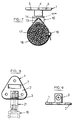
- FIG. 1 an elevational view of a base 1 designed to be fixed on the surface of a partition, wall, or other structural element d 'an aircraft for example.
- This base includes a generally triangular flat base 2 and a projecting sleeve 3 perpendicular to the plane of the base 2.
- Three holes 4, 5, 6 are drilled in the flat part 2 to allow the passage of organs such as screws, rivets etc ... allowing the fixing of the base on a flat surface.
- the face of the flat base 2 from which the sleeve 3 projects further still has a slight rectangular depression 7 suitable for receiving inscriptions, possibly on a label, allowing for example the identification of the cables supported by the base.
- FIG. 2 is a section along the section line II-II of Figure 1, of the sleeve fitted to the base.
- FIG. 3 is an enlarged detail view of the internal surface of the sleeve, taken along arrow F of FIG. 2.
- the internal surface of the sleeve 3 is generally cylindrical and has regular toothing, as it appears more clearly in FIG. 3.
- This toothing 8 extends between the bottom of the socket and an annular groove 9 located near the outlet of this socket.
- the base thus shaped is designed to receive, for example, a head 10 shown in Figures 4 to 6 of the accompanying drawing.
- the head 10 consists of a support or V-shaped cradle 11 secured to a stud or pin 12 shown in more detail in Figure 6.
- the support 11 comprises two wings 11 ′, 11 ⁇ parallel and connected on the one hand, by a base 11 ′ ′ ′ and, on the other hand, by a spacer 13 spaced from the base 11 ′ ′ ′ By a passage 14 whose usefulness will be explained later.
- Figure 6 shows edges 15 of teeth regularly distributed on the periphery of the stud 12. These teeth extend parallel to the axis of the stud from the free end thereof to a circular rib 16. According to the present invention the toothing and the rib formed on the nipple 12 are complementary to the toothing 8 and the groove 9 formed in the sleeve 3 of base 1.
- FIG. 7 the base 1 assumed to be fixed on a support surface (not shown) by means of fixing members passing through the holes 4, 5, 6.
- a head 10 forcibly mounted on the base as indicated above.
- a point of fluid adhesive can be poured into the socket of the base.
- the latter is then advantageously pierced with a hole 20 (see FIGS. 1 and 2) in its bottom to allow the expansion of the excess glue expelled by the stud, outside the base.
- FIG. 7 there is shown diagrammatically in FIG. 7 a bundle 17 of cables, electrical for example, fixed on the support 11 by means of a flexible strap 18 provided with a locking loop 19 of any known type.
- the bracelet 18 passes through the open passage 14 between the base 11 ′ ′ ′ and the spacer 13 (see FIG. 5). It is therefore possible, by tightening the bracelet, to press the bundle of cables on the V-shaped seat defined by the wings 11 ′, 11 ⁇ of the support 11, to ensure the stability of the bundle on the head.
- the opening of the "V" it is possible to adapt the support 11 to the reception of beams of greater or lesser diameter.
- the support assembly thus formed has several advantages. On the one hand it makes it possible to orient the head around the axis of the socket of the base, thanks to the complementary teeth of the socket 8 and of the stud 12.
- the complementary teeth can each extend circularly over 30 ° by example. With such teeth, the head can occupy twelve different positions on the base, which corresponds, due to the symmetry of these positions and of the head 10, to six distinct useful positions.
- Such a possibility of orientation is very valuable in that one can adapt the position of the head to the direction followed by a cable or a bundle of cables running parallel to a support surface, walls or partitions of aircraft cells. for example.
- the angular positioning of the base no longer needs to be fixed with precision, which facilitates the fixing of the base on the support partition.
- the separation into two components of the head and the base introduces on the whole a modularity which provides a great flexibility of adaptation to situations in which the positions cables to be fixed relative to the support partitions are very different.
- This modularity will be widely illustrated in the remainder of the present description, in conjunction with FIGS. 8 to 15.
- the assembly of a support by force insertion of a rib 16 in a groove 9 allows rapid and convenient attachment of the base and the head, possibly removable in the event of modification of the wiring (if the 'we didn't use glue of course).
- Figures 8 to 13 show other embodiments of the base, which can be incorporated into the modular assembly according to the invention.
- identical numerical references to those used in FIGS. 1 to 7 relate to identical or similar elements or members.
- the base shown in elevation in Figure 10 and in front view in Figure 11 differs from that of Figure 1 by its generally rectangular base and not triangular, pierced with two fixing holes 4 and 5 only. Such a base is suitable when the fixing of the base on the support partition can be lightened.
- Figures 12 and 13 correspond to Figures 10 and 11 and relate to a variant of the base shown in these figures, variant according to which the sleeve has an axis parallel to the base 2 of the base and not perpendicular thereto.
- FIG. 14 shows an extension column 21 which essentially comprises, arranged in line on the same axis, a socket 3 ′ and a stud 12 ′ complementary to each other and in accordance with the sockets 3 and the stud 12 of the modes of previous embodiments, respectively.
- Angular locating ribs 22 can be regularly arranged on the periphery of the baluster, just as, moreover, on the periphery of the sockets incorporated in the bases described above.
- FIG. 15 represents a multiple support 23 or crosspiece, which comprises a stud 12 ⁇ conforming to the studs 12 and 12 ′ of the preceding embodiments and, for example, three sockets 31, 32, 33 conforming to the sockets 3 and 3 ′ of the modes of previous achievements.
- the socket 31 is coaxial and in line with the stud 12 ⁇ while the sockets 32 and 33 are arranged head to tail on the same axis perpendicular to that of the stud 12 ⁇ and the socket 31.
- Bases, heads, columns, and cross bars described above can be combined in a wide variety of configurations for adaptation to different cable support conditions. This ability is essential in particular in an aircraft where very long lengths of electrical cables are required to supply and / or interconnect a large number of organs or devices. The topology of the cable passages must then be carefully studied and it is necessary to have means of fixing these cables in the selected passages, which are capable of adapting to complex space conditions.
- the types of support available have been multiplied for this purpose, to the detriment of the costs of manufacturing and storing these supports.
- the modular assembly according to the invention makes it possible, by various combinations of a small number of elements, to have an extended set of such supports, with reduced manufacturing and storage costs.
- FIGS. 8 and 11 show two assemblies which can be produced with the components described above, by way of example only, because the possible assemblies are very numerous because the assembly according to the invention allows to support cables or cable bundles, in any direction of space, parallel or perpendicular to the axis of one of the socket / stud pairs used in a support assembly according to the invention.
- a small column 21 has been mounted on the base shown and a head 10 on the small column 21.
- several small columns could be threaded end to end to vary the distance between the head of the socket and the base .
- the head itself could be installed in any angular position other than that shown.
- the base receives a cross 23, itself equipped with three heads 10. It is thus possible to multiply the number of bundles of cables supported by the same base.
- one or more extension posts could be interposed between the spider and the base.
- other cross-pieces could be interposed between the heads and the base shown in FIG. 11.
Landscapes
- Engineering & Computer Science (AREA)
- General Engineering & Computer Science (AREA)
- Mechanical Engineering (AREA)
- Architecture (AREA)
- Civil Engineering (AREA)
- Structural Engineering (AREA)
- Installation Of Indoor Wiring (AREA)
- Supports For Pipes And Cables (AREA)
Claims (9)
- Modularer Zusammenbau zum Tragen von elektrischen Kabeln mit zumindest zwei Elementen, die jeweils einen Sockel (1), der vorgesehen ist, um auf einer Tragoberfläche befestigt zu werden und einen Kopf (10), der gestaltet ist, um Kabel aufzunehmen, bilden, wobei ein mit einem Element verbundener Ansatz (12) gestaltet ist, um in einer mit einem anderen Element verbundenen Buchse (3) aufgenommen zu werden, so dass sie die Zusammenbau der beiden Elemente sicherstellen, wobei der Zusammenbau dadurch gekennzeichnet ist, daß der Ansatz (12) nacheinander ausgehend von seiner Wurzel koaxial eine ringförmige Rippe (16) und eine seitliche gezahnte Oberfläche (15) aufweist und daß die Buchse (3) nacheinander ausgehend von ihrer Öffnung eine ringförmige Nut (9) und eine seitliche innere gezahnte Oberfläche (8) aufweist, die koaxial und komplementär zu der Rippe (16) und zu der seitlichen Oberfläche (15) des Ansatzes gestaltet sind, um das Einsetzen des Ansatzes (12) in die Buchse (3) folgend einer relativen winkligen Ausrichtung gewählt unter den durch die gezahnten zusammenwirkenden definierten Oberflächen zu erlauben, und das Einsetzen mittels Kraft der Rippe (16) in die Nut, um den Ansatz axial in der Buchse zu blockieren.
- Zusammenbau gemäß Anspruch 1, dadurch gekennzeichnet, daß in Zusammenbaulage die Achse des Ansatzes (12) und der Buchse (3), in die der Ansatz eingesetzt ist, senkrecht zu einer Basis (2) für Anlage des Sockels (1) ist.
- Zusammenbau gemäß Anspruch 1, dadurch gekennzeichnet, daß in Zusammenbauposition die Achse des Ansatzes (12) und der Buchse (3), in die der Ansatz eingesetzt ist, parallel zu einer Basis (2) für Anlage des Sockels (1) ist.
- Zusammenbau gemäß irgendeinem der Ansprüche 1 bis 3, dadurch gekennzeichnet, daß er ein Element (21; 23) aufweist, welches zumindest einen Ansatz (12′, 12˝) und zumindest eine Buchse (3′; 3₁, 3₂, 3₃) komplementär zum Ansatz aufweist.
- Zusammenbau gemäß Anspruch 4, dadurch gekennzeichnet, daß das Element die Form einer Distanzsäule (21) hat, die an einem Ende mit einem Ansatz (12′) versehen ist und mit einer Buchse (3′) am gegenüberliegenden Ende, auf eine Weise, zwischen einen Sockel (1) und einen Kopf (10) gesetzt werden zu können.
- Zusammenbau gemäß Anspruch 4, dadurch gekennzeichnet, daß das Element die Form eines Kreuzstückes (23) hat, das einen Ansatz (12˝) und mehrere Buchsen (3₁, 3₂, 3₃) aufweist, die geeignet sind, um jede den Ansatz eines anderen Elements aufzunehmen.
- Zusammenbau gemäß irgendeinem der Ansprüche 1 bis 6, dadurch gekennzeichnet, daß das Element (10) in Form eines Kopfes die Form eines Sitzes für ein oder mehrere Kabel annimmt und einen Durchgang (14) zum Aufnehmen einen Bandes (18) zur Befestigung des (der) Kabels (Kabel) auf dem Kopf aufweist.
- Zusammenbau gemäß irgendeinem der Ansprüche 1 bis 7, dadurch gekennzeichnet, daß das den Sockel (1) bildende Element eine Fläche (7) aufweist, die geeignet ist, eine Aufschrift zu tragen.
- Zusammenbau gemäß irgendeinem der Ansprüche 1 bis 8, dadurch gekennzeichnet, daß zumindest eines der zusammenzubauenden Teile Ansatz und Buchse von einem Ausdehnungsloch (20) für einen Tropfen Klebstoff, der vor dem Zusammenbau in die Buchse eingebracht ist, durchbohrt ist.
Applications Claiming Priority (2)
| Application Number | Priority Date | Filing Date | Title |
|---|---|---|---|
| FR9006850 | 1990-06-01 | ||
| FR9006850A FR2662866B1 (fr) | 1990-06-01 | 1990-06-01 | Ensemble modulaire de support de cables electriques. |
Publications (2)
| Publication Number | Publication Date |
|---|---|
| EP0459904A1 EP0459904A1 (de) | 1991-12-04 |
| EP0459904B1 true EP0459904B1 (de) | 1994-08-31 |
Family
ID=9397198
Family Applications (1)
| Application Number | Title | Priority Date | Filing Date |
|---|---|---|---|
| EP91401404A Expired - Lifetime EP0459904B1 (de) | 1990-06-01 | 1991-05-30 | Modularer Zusammenbau zum Tragen von elektrischen Kabeln |
Country Status (4)
| Country | Link |
|---|---|
| US (1) | US5169100A (de) |
| EP (1) | EP0459904B1 (de) |
| DE (1) | DE69103678T2 (de) |
| FR (1) | FR2662866B1 (de) |
Families Citing this family (29)
| Publication number | Priority date | Publication date | Assignee | Title |
|---|---|---|---|---|
| DE4225742A1 (de) * | 1992-08-04 | 1994-02-10 | United Carr Gmbh Trw | Halteelement |
| DE4305963C2 (de) * | 1993-02-26 | 1995-04-27 | Deutsche Aerospace Airbus | Abstandhalter für Leitungen, insbesondere für elektrische Leitungsbündel in Flugzeugen |
| US5653409A (en) * | 1995-07-25 | 1997-08-05 | Panduit Corp. | Standoff |
| DE19626453A1 (de) * | 1996-07-02 | 1998-01-08 | Alcatel Kabel Ag | Schelle zum Anbringen eines langgestreckten Gegenstandes an einer Wand |
| US6349904B1 (en) | 1998-05-15 | 2002-02-26 | Arthur A. Polad | Cable bundling and support device |
| US6581885B2 (en) * | 1998-05-15 | 2003-06-24 | Arthur A. Polad | Cable bundling and support device |
| US6276649B1 (en) * | 1999-05-10 | 2001-08-21 | Brian David Kruse | Multifunction adapter for smooth surface mounting |
| DE10135033B4 (de) * | 2001-07-18 | 2005-12-22 | Demag Cranes & Components Gmbh | Schelle für ein zylindrisches Element, insbesondere ein elektrisches Kabel, ein Rohr oder einen Schlauch |
| US6930244B1 (en) * | 2003-06-24 | 2005-08-16 | Michael W. Nebel | Flexible wiring and tubing carrier for slide-out rooms |
| US7134633B2 (en) * | 2004-02-05 | 2006-11-14 | Medcount Systems, L.L.C. | Method and apparatus for securing cables and the like |
| ATE526712T1 (de) * | 2004-10-13 | 2011-10-15 | Airbus Operations Gmbh | Halter zum halten von elektrischen leitungen |
| DE102004049894A1 (de) * | 2004-10-13 | 2006-05-18 | Airbus Deutschland Gmbh | Halter |
| DE202005015875U1 (de) * | 2005-10-07 | 2007-02-15 | S-Fasteners Gmbh | Halter-Anordnung für Kabel o.ä. mit einstellbaren Dreh-Rast-Positionen |
| US7793895B2 (en) * | 2006-06-13 | 2010-09-14 | Avery Dennison Corporation | Cable tie for an automotive valve cover |
| US20080087782A1 (en) * | 2006-09-06 | 2008-04-17 | Scott Sutherland | Accessories for universal mounting system |
| GB0708024D0 (en) * | 2007-04-25 | 2007-06-06 | Airbus Uk Ltd | Stand off support system |
| DE102008041230B4 (de) | 2008-08-13 | 2019-01-17 | Airbus Operations Gmbh | Halter zur Befestigung mindestens einer Leitung |
| GB2486682B (en) * | 2010-12-22 | 2016-08-10 | Tyco Electronics Ltd Uk | A cable breakout support |
| EP2485352A1 (de) * | 2011-02-04 | 2012-08-08 | Eurocopter Deutschland GmbH | Installationssystem für Kabel und Leitungen |
| CA2829748C (en) * | 2011-03-10 | 2019-09-10 | Bombardier Inc. | Standoff device and method of installation of harness |
| FR2978621B1 (fr) * | 2011-07-27 | 2014-03-28 | Snecma | Dispositif de fixation et de maintien d'au moins un harnais electrique dans une turbomachine |
| FR2991113A1 (fr) * | 2012-05-24 | 2013-11-29 | Airbus Operations Sas | Ensemble de dispositifs et procede pour la fixation de torons electriques dans un aeronef |
| US10720263B2 (en) | 2013-10-31 | 2020-07-21 | Electrical Materials Company | Electrical cable support arrangement |
| US9895031B2 (en) * | 2015-08-18 | 2018-02-20 | Shaoxing County Runzhuo Home Textile Co. LTD | Quick release curtain support assembly |
| DE102015121271B3 (de) * | 2015-12-07 | 2017-04-13 | Sfs Intec Holding Ag | Leitungshalter |
| FR3055033B1 (fr) * | 2016-08-12 | 2019-05-17 | Safran Electrical & Power | Dispositif de fixation d'au moins un cable dans un aeronef ou moteur d'aeronef ou pour application spatiale |
| EP3336989B1 (de) * | 2016-12-16 | 2020-07-22 | HellermannTyton GmbH | Kabelfixierungsvorrichtung |
| US11384814B2 (en) | 2020-04-15 | 2022-07-12 | Panduit Corp. | Compliant hanger assembly |
| FR3130088B1 (fr) * | 2021-12-02 | 2023-12-29 | Amphenol Air Lb | Dispositif de fixation d’un objet sur une structure |
Family Cites Families (15)
| Publication number | Priority date | Publication date | Assignee | Title |
|---|---|---|---|---|
| US1971396A (en) * | 1933-06-02 | 1934-08-28 | Walde Hal De | Cementable support for wall fixtures |
| US2161782A (en) * | 1938-10-21 | 1939-06-13 | David B Flower | Pipe hanger |
| US2539783A (en) * | 1948-05-11 | 1951-01-30 | American Tube Products Inc | Ring pipe hanger |
| US2949304A (en) * | 1957-03-01 | 1960-08-16 | Willis S Williams | Golf putter handle |
| US3556447A (en) * | 1968-08-06 | 1971-01-19 | Trw Inc | Support for elongate members |
| GB1545781A (en) * | 1976-03-24 | 1979-05-16 | Scandinavian Fittings Ltd | Supporting means comprising an interengageable bracket and holder such as a wall bracket |
| AU516939B2 (en) * | 1976-04-08 | 1981-07-02 | Upl Group Ltd. | Tap handles and means for mounting same |
| DE7730437U1 (de) * | 1977-10-01 | 1978-01-12 | Fa. A. Raymond, 7850 Loerrach | Trägerplatte zur Halterung von Kabel- oder Schlauchklemmen |
| FR2496349A1 (fr) * | 1980-12-15 | 1982-06-18 | Aerospatiale | Dispositif pour le support d'objets allonges tels que cables, faisceaux de cables ou analogues et installations comportant de tels dispositifs |
| US4768741A (en) * | 1987-04-30 | 1988-09-06 | Logsdon Duane D | Pipe hangers |
| US4771743A (en) * | 1987-08-17 | 1988-09-20 | Mcdowell International Packaging Systems, Inc. | Spark plug wire loom |
| US4786025A (en) * | 1987-08-27 | 1988-11-22 | Eee Corporation | Anti-twist signholder support assembly |
| US4827654A (en) * | 1988-01-13 | 1989-05-09 | Roberts Joseph M | Fishing rod holder for casting and spinning reels |
| DE3933305A1 (de) * | 1989-10-05 | 1991-04-18 | United Carr Gmbh Trw | Halteelement aus kunststoff |
| US5022104A (en) * | 1990-07-31 | 1991-06-11 | Cedric C. Miller | Shower curtain support |
-
1990
- 1990-06-01 FR FR9006850A patent/FR2662866B1/fr not_active Expired - Lifetime
-
1991
- 1991-05-13 US US07/698,828 patent/US5169100A/en not_active Expired - Fee Related
- 1991-05-30 DE DE69103678T patent/DE69103678T2/de not_active Expired - Fee Related
- 1991-05-30 EP EP91401404A patent/EP0459904B1/de not_active Expired - Lifetime
Also Published As
| Publication number | Publication date |
|---|---|
| DE69103678T2 (de) | 1995-04-06 |
| DE69103678D1 (de) | 1994-10-06 |
| US5169100A (en) | 1992-12-08 |
| EP0459904A1 (de) | 1991-12-04 |
| FR2662866B1 (fr) | 1992-11-27 |
| FR2662866A1 (fr) | 1991-12-06 |
Similar Documents
| Publication | Publication Date | Title |
|---|---|---|
| EP0459904A1 (de) | Modularer Zusammenbau zum Tragen von elektrischen Kabeln | |
| CA2120431C (fr) | Connecteur electrique pourvu d'une pluralite de modules de connexion disposes en lignes et colonnes | |
| EP0725464B1 (de) | Sockel für einen Schaltschrank oder dergleichen und Schrank mit einen solchen Sockel | |
| EP2445060A1 (de) | Verbindungssystem zwischen elektronischen karten | |
| FR3033018A1 (fr) | Piece de support d'element tubulaire, notamment pour aeronef. | |
| WO1989011043A1 (fr) | Dispositif d'assemblage pour elements demontables ou modulaires | |
| EP0987451B1 (de) | Verbessertes Gestell für automatische Farbmisch-Maschinen | |
| FR2640702A1 (fr) | Dispositif pour la fixation de poutres en treillis | |
| CA2117251C (fr) | Connecteur electrique pourvu d'une pluralite de modules de connexion | |
| EP1657992A1 (de) | Vorrichtung zur befestigung eines endes eines bandes auf einem gegenstand | |
| FR2799338A1 (fr) | Ensemble de modules pour la realisation de boites a fusibles | |
| EP2571113B1 (de) | Befestigungs- und Schnellverbindungsvorrichtung für zweiteiligen Anschluss | |
| CA3068214C (fr) | Troncon de mat d'eolienne, mat d'eolienne et procede d'assemblage | |
| EP0319410B1 (de) | Vorrichtung zum Abstützen von länglichen Gegenständen wie Kabel oder Rohre | |
| FR2849967A1 (fr) | Dispositif de fixation pour connecteur comprenant deux parties. | |
| WO2009018914A1 (fr) | Dispositif de fixation comportant au moins un boulon et un ecrou cooperants | |
| FR3078054A1 (fr) | Plateforme flottante a structure modulaire | |
| FR2638210A1 (fr) | Piece de liaison destinee a l'assemblage de profiles | |
| EP0014123A2 (de) | Verfahren und Vorrichtung zum miteinander Verbinden von Kanalteilstücken mit Fluidumzug | |
| EP0358565A2 (de) | Stützvorrichtung für Pflanzen | |
| EP0744088A1 (de) | Elektrische stecker in englischer ausführung | |
| EP1557502B1 (de) | Umkehrbares Solidarisierungselement, Bretter und Ordnen, die solche Elemente verwirklichen | |
| EP1376807A1 (de) | Schnellbefestigungsvorrichtung für Wandkabelkanal | |
| EP1541018B1 (de) | Zaunpfahlen | |
| FR2717629A1 (fr) | Support pour boîtier de calculateur. |
Legal Events
| Date | Code | Title | Description |
|---|---|---|---|
| PUAI | Public reference made under article 153(3) epc to a published international application that has entered the european phase |
Free format text: ORIGINAL CODE: 0009012 |
|
| AK | Designated contracting states |
Kind code of ref document: A1 Designated state(s): DE GB |
|
| 17P | Request for examination filed |
Effective date: 19911223 |
|
| 17Q | First examination report despatched |
Effective date: 19931103 |
|
| GRAA | (expected) grant |
Free format text: ORIGINAL CODE: 0009210 |
|
| AK | Designated contracting states |
Kind code of ref document: B1 Designated state(s): DE GB |
|
| REF | Corresponds to: |
Ref document number: 69103678 Country of ref document: DE Date of ref document: 19941006 |
|
| GBT | Gb: translation of ep patent filed (gb section 77(6)(a)/1977) |
Effective date: 19940909 |
|
| PLBE | No opposition filed within time limit |
Free format text: ORIGINAL CODE: 0009261 |
|
| STAA | Information on the status of an ep patent application or granted ep patent |
Free format text: STATUS: NO OPPOSITION FILED WITHIN TIME LIMIT |
|
| 26N | No opposition filed | ||
| PGFP | Annual fee paid to national office [announced via postgrant information from national office to epo] |
Ref country code: GB Payment date: 19980522 Year of fee payment: 8 |
|
| PGFP | Annual fee paid to national office [announced via postgrant information from national office to epo] |
Ref country code: DE Payment date: 19980721 Year of fee payment: 8 |
|
| PG25 | Lapsed in a contracting state [announced via postgrant information from national office to epo] |
Ref country code: GB Free format text: LAPSE BECAUSE OF NON-PAYMENT OF DUE FEES Effective date: 19990530 |
|
| GBPC | Gb: european patent ceased through non-payment of renewal fee |
Effective date: 19990530 |
|
| PG25 | Lapsed in a contracting state [announced via postgrant information from national office to epo] |
Ref country code: DE Free format text: LAPSE BECAUSE OF NON-PAYMENT OF DUE FEES Effective date: 20000301 |