EP1541018B1 - Zaunpfahlen - Google Patents
Zaunpfahlen Download PDFInfo
- Publication number
- EP1541018B1 EP1541018B1 EP04292764A EP04292764A EP1541018B1 EP 1541018 B1 EP1541018 B1 EP 1541018B1 EP 04292764 A EP04292764 A EP 04292764A EP 04292764 A EP04292764 A EP 04292764A EP 1541018 B1 EP1541018 B1 EP 1541018B1
- Authority
- EP
- European Patent Office
- Prior art keywords
- post
- main portion
- recess
- assembly
- post according
- Prior art date
- Legal status (The legal status is an assumption and is not a legal conclusion. Google has not performed a legal analysis and makes no representation as to the accuracy of the status listed.)
- Expired - Lifetime
Links
- 125000006850 spacer group Chemical group 0.000 claims description 18
- 239000004020 conductor Substances 0.000 claims description 7
- 239000004033 plastic Substances 0.000 claims description 5
- 239000000463 material Substances 0.000 claims description 2
- 230000000712 assembly Effects 0.000 claims 1
- 238000000429 assembly Methods 0.000 claims 1
- 239000002184 metal Substances 0.000 description 3
- 229910052751 metal Inorganic materials 0.000 description 3
- XEEYBQQBJWHFJM-UHFFFAOYSA-N Iron Chemical compound [Fe] XEEYBQQBJWHFJM-UHFFFAOYSA-N 0.000 description 2
- WABPQHHGFIMREM-UHFFFAOYSA-N lead(0) Chemical compound [Pb] WABPQHHGFIMREM-UHFFFAOYSA-N 0.000 description 2
- 230000000295 complement effect Effects 0.000 description 1
- 239000011152 fibreglass Substances 0.000 description 1
- 239000012212 insulator Substances 0.000 description 1
- 229910052742 iron Inorganic materials 0.000 description 1
- 239000002991 molded plastic Substances 0.000 description 1
Images
Classifications
-
- E—FIXED CONSTRUCTIONS
- E04—BUILDING
- E04H—BUILDINGS OR LIKE STRUCTURES FOR PARTICULAR PURPOSES; SWIMMING OR SPLASH BATHS OR POOLS; MASTS; FENCING; TENTS OR CANOPIES, IN GENERAL
- E04H17/00—Fencing, e.g. fences, enclosures, corrals
- E04H17/14—Fences constructed of rigid elements, e.g. with additional wire fillings or with posts
- E04H17/20—Posts therefor
Definitions
- the present invention relates to a stake for electric fence. More particularly the invention relates to a stake for quickly mounting a temporary fence.
- the user circulating around the parcel to be fenced uses stakes from a bundle composed of a plurality of stakes. Either the stakes of the bundle are simply held together by links when they have just been bought, or the stakes are in bulk when they are used. It is therefore difficult to manipulate the bundle or extract a single stake from the bundle without the whole bundle is stripped.
- the invention therefore aims to provide a fence post adapted to be secured to orsupplementarydidarisé a set of stakes so as to form a bundle having a certain rigidity.
- the invention relates to an electric fence post comprising a tip portion, made of metal or plastic, intended to be stuck in the ground and a main portion, comprising along said main portion, one or more connecting means for secure a plurality of such fence stakes to form an easily transportable bundle, characterized in that said main portion is of plastic material, and in that said connecting means are at least partially integrally molded with said main portion.
- the connecting means comprise pairing means for assembling the stake with another such stake, the pairing means being constituted by a male element and a female element, the male element being intended to be assembled to a female element of the other such stake, the female element being intended to be assembled to a male element of the other such stake.
- an element between said male element and saidfemale element is connected in the vicinity of a first end of the main portion located on the side of the tip portion, the other element being connected in the vicinity of a second end of the main portion located opposite the first end of the main portion.
- the pairing means comprise a spacer element arranged radially with respect to the axial direction of the post, a first end of the spacer element being connected to the main portion, a second end of the element of FIG. spacing, opposite its first end, carrying one of said male member and said female member, the spacer member for spacing the stake from the other such stake with which it is assembled.
- the spacer element is located near a first end of the main portion adjacent to the tip portion, and the spacer element has a bearing face generally perpendicular to the axial direction of the peg, to facilitate the operation of filleting the earth stake.
- the connecting means comprise assembly means for securing together a plurality, greater than two, such stakes.
- the assembly means are constituted by at least one connecting rod and at least one through hole located along the main portion to pass said connecting rod.
- the main portion comprises two through holes, a first through hole being located at a first end of the main portion located near the tip portion and a second through hole being located at a second end of the main portion to the opposite of the first end.
- one of the through holes is a circular hole, and the other of the through holes is an oblong hole whose major axis is oriented in the axial direction of the stake.
- the assembly means are constituted by at least one recess-lug assembly disposed radially relative to the axial direction, the lug being intended to cooperate with a corresponding recess of a second other such stake, said recess being intended to cooperate with a corresponding lug of a third other such stake.
- the main portion comprises two sets recess - lug, a first set being located at a first end of the main portion located near the tip portion and a second assembly being located at a second end of the main portion to the opposite of the first end.
- the lug and the recess of the same assembly are arranged radially in opposite directions.
- the recess of said at least one recess-lug assembly is a through recess.
- the stake may include conductor support means located along the main portion.
- the support means act as assembly means adapted to receive a connecting rod solidarisant a plurality of stakes.
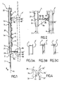
- the fence post 1 defines an axial direction marked by the axis A.
- the fence post 1 comprises a tip portion 2 intended to be stuck in the earth, for example metal, and a main portion 3, for example molded plastic, in a known manner.
- the main portion 3 has a first end 31 located in the vicinity of the tip portion 2, and a second end 32, free, located opposite the first end 31.
- the junction 23 between the metal tip portion 2 and the first end 31 of the main portion 3 is made by means of a cylindrical recess 24 of axis A provided in the main portion 3.
- the corresponding end of the tip portion is forcibly housed in the cylindrical recess 24.
- the cross section of the main portion 3 (FIG. 4) is I-shaped and comprises a first flank 33 and a second flank 35 connected to one another by a rib 34.
- One of the flanks, here the first flank 33 comprises conductor support means 5 and 6 for holding the lead wire in a direction B perpendicular to the axis A.
- the fence post 1 is equipped with connecting means whose function is to allow the assembly of a plurality of fence posts 1 to form a bundle easily transportable without it disintegrating.
- the bundle is a rigid group of fence posts.
- the connecting means comprise matching means for forming a group consisting of a pair of stakes.
- the pairing means consist of elements arranged along the peg 1 so that they cooperate with corresponding elements placed along another peg 1 '(shown in dashed lines in Figure 1).
- the pairing means are constituted by a male element 81, for example a cylinder of small diameter with an axis parallel to the axis B and a female element 82.
- the female element 82 is for example located on the main portion 3, near the second end 32 thereof.
- the male element 81 is for example located at the end of a spacer element 83 also part of the pairing means.
- the shape of the female element 82 is complementary to that of the male element 81.
- the female element 82 is a hollow cylinder portion of axis parallel to the axis B and has a crescent section, so as to receive a male element 82 'of another stake 1' and to allow the passage of the corresponding spacing element 83 '.
- the spacer element 83 is disposed near the first end 31 of the main portion 3 and extends perpendicular to the axial direction A of the post 1.
- a free end of the spacer element 83 carries the element 81.
- the spacer element 83 is flattened in a plane perpendicular to the axial direction A so as to have a flat bearing surface 85 on the side of the main portion 3.
- the bearing face 85 allows the user to file the fence post 1 earth by using the foot by pressing on the bearing face 85.
- the bearing face 85 may be provided with anti-slip streaks 86 ( Figure 2).
- a rib 84 may be provided between the face of the spacer element 83 opposite the bearing face 85 and the junction between the main portion 3 and the portion peak 2.
- a second fence post 1 ' is shown in dashed lines.
- the first and second fence posts 1 and 1 ' are placed head to tail so that the male element 81 of the first post 1 is opposite the female element 82' of the second post 1 ', and the element male 81 'of the second stake 1' is opposite the female element 82 of the first stake 1.
- the male and female elements are then nested with each other either by snapping or sliding parallel to the axis B , male elements in the female elements.
- FIG. 3A shows a pair of pegs constituted by two stakes 1 and 1 ', according to the presently preferred embodiment, associated head to tail.
- the two stakes could be associated to form a pair of T-shaped stakes (FIG. 3B).
- the respective second flanks of each of the stakes are facing each other.
- the pairing elements are therefore provided externally on the second sidewall 35 of the post 1.
- the two stakes being strictly identical (formed from a single mold), the elements intended to cooperate must be placed opposite each other. So the two stakes of the pair of stakes being oriented in the same direction, the stakes are slightly offset relative to each other along the axis A.
- FIG. 3C represents yet another variant of the embodiment of a pair of stakes.
- the stakes are associated head to tail but facing outwards.
- the pairing means are therefore provided externally on the second side 35 of the stakes 1 and 1 '. It should be noted that in the pairings of FIGS. 3B and 3C, the stakes may possibly not be provided with the spacer element 83.
- the connecting means of the stake 1 are constituted by assembly means for forming a group consisting of a plurality of stakes, the plurality comprising at least three stakes. It should be noted that the stake according to the invention may comprise assembly means without including means of pairing having the function of associating two stakes.
- the assembly means comprise a plurality of through holes arranged along the main portion 3.
- the through holes pass right through the rib 34, along the axis B.
- the main portion 3 has a first through hole 71 in the vicinity of its first end 31 and has a second through hole 72 in the vicinity of its second end 32.
- the first through hole 71 is circular while the second through hole 72 is oblong shape, the major axis of this oblong hole being oriented along the axis A.
- the through holes 71 and 72 are intended to cooperate with a connecting rod as will now be described.
- the assembly means make it possible to form a group consisting of several pairs of stakes made as described above.
- the pairs of stakes are superimposed on each other, possibly alternately: the peg, for example on the right, of each pair of pegs is once pointed up, once pointing down.
- the through holes equipping the main portions of the pegs of the superimposed pairs coincide along four axes.
- An attached connecting rod can thus be driven through a succession of through holes to frictionally hold the corresponding stakes.
- up to four stems can be used ensures rigidity to the bundle thus formed.
- the fact that a through hole in two along the axis of the connecting rod is an oblong hole reduces friction and allows the user to easily disconnect one of the pairs of stakes of the bundle.
- the assembly means are constituted by at least one lug-recess assembly, which is a variant of the set-insert-through-hole assembly.
- the post comprises two such ergot-recess respectively placed at each of the ends of the main portion 3 to allow safe assembly.
- the peg 1 has a lug 91 placed on one side of the rib 34 and extending radially so as to protrude beyond the first and second sidewalls 33 and 35 of the peg 1. As the peg 1 'shown in broken lines, the peg 1 also comprises a recess 92, or non-through hole, located on the face of the rib 34 opposite the face bearing the lug 91.
- the lug 91 of the stake 1 is placed opposite the corresponding recess 92' of the peg 1 'and is forcibly engaged in the recess 92'.
- the lug and the recess of the same assembly being placed on opposite sides of the rib 34, the recess 92 of the stake 1 is intended to receive the lug of a third stake.
- the recess 92 is not necessarily positioned at the same height along the stake as the pin 91. Consequently two stakes secured by these assembly means will be slightly offset relative to each other, for example by a predefined step downwards. So that a third stake, associated with the previous two, is not shifted from the predefined pitch downward, it is possible to provide that a recess-lug assembly will include for example two adjacent recesses (or two adjacent lugs) spaced two times said predefined step and a lug (a recess). Thus, the third stake of the fagot will be at the level of the first post of the bundle.
- the recess may be a through hole in which the lug is snapped.
- the support means of the conductor 5 or 6 can serve as assembly means.
- An attached rod fitting perfectly to the means of the conductor support 5 or 6 allows forming a group consisting of a plurality of stakes.
- the shape of the conductor support means 5, 6 is studied to ensure the connection of a stake to another.
- the stake according to the invention is easily associated with other stakes to form a rigid bundle, easy to store and move.
Landscapes
- Engineering & Computer Science (AREA)
- Architecture (AREA)
- Civil Engineering (AREA)
- Structural Engineering (AREA)
- Fencing (AREA)
Claims (14)
- Zaunpfahl (1, 1') für einen Elektrozaun, mit einer Spitze (2) zum Einstechen in den Boden und einem Hauptteil (3), der längs des Hauptteils ein oder mehrere Verbindungsmittel (71, 72, 81, 82, 83, 91, 92) aufweist, die es ermöglichen, eine Anzahl solcher Zaunpfähle miteinander zu verbinden, um ein leicht transportierbares Bündel zu bilden, dadurch gekennzeichnet, dass der Hauptteil (3) aus Kunststoff besteht und dass die Verbindungsmittel (71, 72, 81, 82, 83, 91, 92) mindestens teilweise einstückig mit dem Hauptteil geformt sind.
- Zaunpfahl nach Anspruch 1, dadurch gekennzeichnet, dass die Verbindungsmittel Kupplungsmittel zum Verbinden des Zaunpfahls (1) mit einem anderen Zaunpfahl (1') aufweisen, wobei die Kupplungsmittel aus einem Einsteckelement (81) und einem Aufnahmeelement (82) bestehen, wobei das Einsteckelement (81) zum Zusammenfügen mit einem Aufnahmeelement (82') des anderen Zaunpfahls und das Aufnahmeelement (82) zum Zusammenfügen mit einem Einsteckelement (81) des anderen Zaunpfahls bestimmt ist.
- Zaunpfahl nach Anspruch 2, dadurch gekennzeichnet, dass von dem Einsteckelement (81) und dem Aufnahmeelement (82) das eine in der Nähe eines der Spitze (2) zugewendeten ersten Endes (31) des Hauptteils (3) angebracht ist und das andere Element in der Nähe eines zweiten Endes (32) des Hauptteils (3), das entgegengesetzt dem ersten Ende (31) des Hauptteils (3) angeordnet ist, angebracht ist.
- Zaunpfahl nach Anspruch 2, dadurch gekennzeichnet, dass die Kupplungsmittel ein Abstandselement (83) aufweisen, welches radial bezüglich der Axialrichtung (A) des Zaunpfahls (1) angeordnet ist, wobei ein erstes Ende des Abstandselements mit dem Hauptteil (3) verbunden ist, und ein dem ersten Ende entgegengesetztes zweites Ende des Abstandselements ein Einsteckelement (81) oder Aufnahmeelement (82) trägt, wobei das Abstandselement es gestattet, den Zaunpfahl (1) auf Abstand von dem anderen Zaunpfahl (1') mit dem er zusammengefügt wird, zu halten.
- Zaunpfahl nach Anspruch 4, dadurch gekennzeichnet, dass das Abstandselement (83) in der Nähe eines ersten Endes (31) des Hauptteils (3) angrenzend an die Spitze (2) angeordnet ist, und dass das Abstandselement eine Aufstützfläche (85) aufweist, die allgemein rechtwinkelig zu der Axialrichtung (A) des Zaunpfahls ist, um das Einstechen des Zaunpfahls in den Boden zu erleichtern.
- Zaunpfahl nach Anspruch 1, dadurch gekennzeichnet, dass die Verbindungsmittel Mittel zum Zusammenfügen aufweisen, die es ermöglichen, eine Anzahl von mehr als zwei derartiger Zaunpfähle miteinander zu verbinden.
- Zaunpfahl nach Anspruch 6, dadurch gekennzeichnet, dass die Kupplungsmittel aus mindestens einer Verbindungsstange und mindestens einem durchgehenden Loch (71, 72) bestehen, welches innerhalb der Länge des Hauptteils (3) angeordnet ist, um die Verbindungsstange durchtreten zu lassen.
- Zaunpfahl nach Anspruch 7, dadurch gekennzeichnet, dass der Hauptteil (2) durchgehende Löcher aufweist, wobei ein erstes durchgehendes Loch (71) an einem ersten Ende (31) des Hauptteils (3) angeordnet ist, der in der Nähe der Spitze angeordnet ist, und dass ein zweites durchgehendes Loch (32) an einem zweiten Ende (32) des Hauptteils (3) angeordnet ist, das auf dem ersten Ende (31) entgegengesetzt ist.
- Zaunpfahl nach nach Anspruch 8, dadurch gekennzeichnet, dass eines der beiden durchgehenden Löcher (31) ein rundes Loch ist und dass das andere der durchgehenden Löcher (72) ein Langloch ist, dessen große Achse in Axialrichtung (A) des Zaunpfahls ausgerichtet ist.
- Zaunpfahl nach Anspruch 1, dadurch gekennzeichnet, dass die Verbindungsmittel aus mindestens einem Paar Ausnehmung (91)- Zapfen (92) bestehen, das radial bezüglich der Axialrichtung angeordnet ist, wobei der Zapfen dazu bestimmt ist, mit einer korrespondierenden Ausnehmung eines zweiten derartigen Zaunpfahls (1') zusammenzuwirken und die Aufnehmung dazu bestimmt, ist mit einem entsprechenden Zapfen eines dritten derartigen Zaunpfahls zusammenzuwirken.
- Zaunpfahl nach Anspruch 10, dadurch gekennzeichnet, dass der Hauptteil zwei Paare von Ausnehmung- Zapfen aufweist, wobei ein erstes Paar an einem ersten Ende (31) des Hauptteils (3) in der Nähe der Spitze (2) angeordnet ist und ein zweites Paar an einem zweiten Ende (32) des Hauptteils (3) angeordnet ist, das dem ersten Ende (31) entgegengesetzt ist.
- Zaunpfahl nach Anspruch 10, dadurch gekennzeichnet, dass der Zapfen (31) und die Ausnehmung radial in entgegengesetzten Richtungen angeordnet sind.
- Zaunpfahl nach Anspruch 10, dadurch gekennzeichnet, dass die Ausnehmung des mindestens einen Paares Ausnehmung - Zapfen eine durchgehende Ausnehmung ist.
- Zaunpfahl nach Anspruch 6, dadurch gekennzeichnet, dass er Haltemittel (5, 6) für einen Leiter aufweist, die entlang des Hauptteils (3) angeordnet sind, wobei die Haltemittel die Funktion von Kupplungsmitteln haben zur Aufnahme einer Verbindungsstange, die eine Mehrzahl derartiger Zaunpfähle miteinander verbindet.
Priority Applications (1)
| Application Number | Priority Date | Filing Date | Title |
|---|---|---|---|
| PL04292764T PL1541018T3 (pl) | 2003-12-12 | 2004-11-24 | Paliki ogrodzenia zgrupowane przez samo-połączenie |
Applications Claiming Priority (2)
| Application Number | Priority Date | Filing Date | Title |
|---|---|---|---|
| FR0314577 | 2003-12-12 | ||
| FR0314577A FR2863452B1 (fr) | 2003-12-12 | 2003-12-12 | Piquets de cloture associes par auto-assemblage |
Publications (2)
| Publication Number | Publication Date |
|---|---|
| EP1541018A1 EP1541018A1 (de) | 2005-06-15 |
| EP1541018B1 true EP1541018B1 (de) | 2007-01-24 |
Family
ID=34508649
Family Applications (1)
| Application Number | Title | Priority Date | Filing Date |
|---|---|---|---|
| EP04292764A Expired - Lifetime EP1541018B1 (de) | 2003-12-12 | 2004-11-24 | Zaunpfahlen |
Country Status (6)
| Country | Link |
|---|---|
| US (1) | US7451964B2 (de) |
| EP (1) | EP1541018B1 (de) |
| DE (1) | DE602004004485T2 (de) |
| FR (1) | FR2863452B1 (de) |
| NZ (1) | NZ537088A (de) |
| PL (1) | PL1541018T3 (de) |
Families Citing this family (2)
| Publication number | Priority date | Publication date | Assignee | Title |
|---|---|---|---|---|
| US10170221B2 (en) | 2012-03-30 | 2019-01-01 | Gallagher Group Limited | Fence standard |
| US12252895B2 (en) * | 2016-02-19 | 2025-03-18 | Gallagher Group Limited | Fence post |
Family Cites Families (26)
| Publication number | Priority date | Publication date | Assignee | Title |
|---|---|---|---|---|
| US404856A (en) * | 1889-06-11 | Folding adjustable fence-panel | ||
| US2647267A (en) * | 1951-06-05 | 1953-08-04 | Ira J Mclaughlin | Knockdown bunk bed |
| US3204606A (en) * | 1963-11-08 | 1965-09-07 | Ira B Parr | Articulated livestock panels |
| US3469822A (en) * | 1968-02-23 | 1969-09-30 | Joseph Francis O Brien | Portable enclosure |
| US3711066A (en) * | 1971-08-06 | 1973-01-16 | L Niemiec | Snap lock plastic fencing |
| US3988009A (en) * | 1973-08-15 | 1976-10-26 | Mann William C | Board-type fence |
| US3910560A (en) * | 1974-02-21 | 1975-10-07 | Harold E Goetz | Coupling means for portable fencing and the like |
| US4022436A (en) * | 1976-01-19 | 1977-05-10 | Thomas Ramon L | Sectional support fence |
| US4371148A (en) * | 1976-07-29 | 1983-02-01 | Harden Richard L | Pivotal connection for enclosure sections |
| US4130272A (en) * | 1977-09-22 | 1978-12-19 | Emmie George W | Flexible picket fence |
| US4370088A (en) * | 1980-11-03 | 1983-01-25 | Mcshane Peter F | Portable fencing loading means |
| NZ203823A (en) * | 1983-10-08 | 1987-07-31 | Jan Henry Weir | Fence dropper: two halves clip together to capture wires |
| FR2565780B1 (fr) * | 1984-06-19 | 1986-10-31 | Cognet Guy | Installation de cloture electrique en particulier pour paturages |
| US4836143A (en) * | 1988-02-08 | 1989-06-06 | Shadbolt Jr George W | Portable livestock handling panel |
| US4930753A (en) * | 1988-08-10 | 1990-06-05 | Alvyn Alvin E | Moldable edge connecting apparatus |
| FR2638060A1 (fr) * | 1988-10-26 | 1990-04-27 | Hamm Jean Jacques | Piquet a systeme d'ancrage resistant aux efforts horizontaux |
| US4919463A (en) * | 1989-02-13 | 1990-04-24 | Mcquade Donald E | Gate locking device |
| US5063876A (en) * | 1990-07-06 | 1991-11-12 | William C. Velvin | Means and methods for training and containing animals |
| US5101595A (en) * | 1991-06-27 | 1992-04-07 | David Rhoades | Automatic gate opener with safety provisions |
| US5362030A (en) * | 1993-01-15 | 1994-11-08 | Iler Jr Ralph K | Fence post module |
| DE29509654U1 (de) * | 1995-06-20 | 1995-08-10 | Horizont Gerätewerk GmbH, 34497 Korbach | Weidezaunpfahl |
| US5794990A (en) * | 1997-01-13 | 1998-08-18 | Protect-A-Child Pool Fence Systems | Safety latch for pool fence |
| US5964548A (en) * | 1997-03-27 | 1999-10-12 | Hi-Qual Manufacturing Ltd. | Panel connector |
| US6578827B2 (en) * | 1999-09-02 | 2003-06-17 | Mccracken Ronald G. | Handrail system |
| US6866251B2 (en) * | 2002-05-28 | 2005-03-15 | Lars Rosaen | Fencing system |
| US7494111B2 (en) * | 2003-10-24 | 2009-02-24 | Flex-Safe, Inc. | Portable collapsible safety barrier |
-
2003
- 2003-12-12 FR FR0314577A patent/FR2863452B1/fr not_active Expired - Fee Related
-
2004
- 2004-11-24 EP EP04292764A patent/EP1541018B1/de not_active Expired - Lifetime
- 2004-11-24 PL PL04292764T patent/PL1541018T3/pl unknown
- 2004-11-24 DE DE602004004485T patent/DE602004004485T2/de not_active Expired - Lifetime
- 2004-12-07 US US11/004,965 patent/US7451964B2/en not_active Expired - Lifetime
- 2004-12-09 NZ NZ537088A patent/NZ537088A/en not_active IP Right Cessation
Also Published As
| Publication number | Publication date |
|---|---|
| NZ537088A (en) | 2006-02-24 |
| DE602004004485D1 (de) | 2007-03-15 |
| FR2863452B1 (fr) | 2007-01-26 |
| EP1541018A1 (de) | 2005-06-15 |
| US20050167642A1 (en) | 2005-08-04 |
| US7451964B2 (en) | 2008-11-18 |
| PL1541018T3 (pl) | 2007-06-29 |
| DE602004004485T2 (de) | 2007-11-15 |
| FR2863452A1 (fr) | 2005-06-17 |
Similar Documents
| Publication | Publication Date | Title |
|---|---|---|
| WO2004043306A1 (fr) | Cage intervertebrale a lame d’ancrage mediane | |
| FR2631396A1 (fr) | Dispositif d'assemblage pour elements demontables ou modulaires | |
| FR2966289A1 (fr) | Systeme d'interconnexion entre des cartes electroniques. | |
| EP0132212A1 (de) | Aus Modulen bestehendes Spielzeug | |
| EP2286492B1 (de) | Bürstenhaltereinrichtung und verwendung dafür zur herstellung eines kraftfahrzeuganlassers | |
| FR2524215A1 (fr) | Traversee a serre-cable | |
| FR2844962A1 (fr) | Dispositif de fixation de lames a des flasques solidaires en rotation d'un arbre rotatif et machine agricole equipee d'un tel dispositif | |
| EP0150698B1 (de) | Baustein eines Aufbausystems | |
| EP3521536B1 (de) | Teil zur befestigung mindestens eines gitterpaneels an einem zaunpfosten, entsprechender zaunpfosten | |
| EP0098784A1 (de) | Elastisches Montageverfahren von zwei Teilen | |
| EP1541018B1 (de) | Zaunpfahlen | |
| WO1981002970A1 (fr) | Assemblage elastique par exemple bracelet ou bague | |
| FR2993720A1 (fr) | Rampe de support de cables electriques pour aeronef | |
| EP0744088B1 (de) | Elektrischer stecker in englischer ausführung | |
| EP2730982B1 (de) | Batteriebefestigung mit verbessertem kontakt | |
| FR3077321A1 (fr) | Piece de fixation d'au moins un panneau de grillage a un poteau de cloture, poteau de cloture et outil de pose correspondants | |
| EP0358565A2 (de) | Stützvorrichtung für Pflanzen | |
| EP2950677B1 (de) | Dekorelement mit einer anzahl von in einem geschlossenen rahmen angeordneten steinen und zwei dekorativen flächen | |
| WO2017207908A1 (fr) | Article de bijouterie et/ou de joaillerie présentant au moins deux pièces mobiles en rotation l'une par rapport à l'autre | |
| FR2763925A1 (fr) | Dispositif de deplacement de charge | |
| FR2575112A1 (fr) | Tete d'impression a roues supportees par une surface de montage courbe | |
| FR2771304A1 (fr) | Procede de fabrication d'une figurine pour jeu de table, figurine ainsi obtenue et jeu de table pourvu d'une telle figurine | |
| FR2851267A1 (fr) | Dispositif permettant d'associer des barrieres | |
| EP2469672B1 (de) | Befestigungsvorrichtung eines elektrischen Anschlussmoduls zum Einrasten auf einer Schiene oder einer durchbohrten Halterung | |
| EP0545837B1 (de) | Herstellungsverfahren für eine Markierungentragende Vorrichtung zum Bezeichnen von Leitern |
Legal Events
| Date | Code | Title | Description |
|---|---|---|---|
| PUAI | Public reference made under article 153(3) epc to a published international application that has entered the european phase |
Free format text: ORIGINAL CODE: 0009012 |
|
| AK | Designated contracting states |
Kind code of ref document: A1 Designated state(s): AT BE BG CH CY CZ DE DK EE ES FI FR GB GR HU IE IS IT LI LU MC NL PL PT RO SE SI SK TR |
|
| AX | Request for extension of the european patent |
Extension state: AL HR LT LV MK YU |
|
| 17P | Request for examination filed |
Effective date: 20050525 |
|
| AKX | Designation fees paid |
Designated state(s): DE FR PL |
|
| GRAP | Despatch of communication of intention to grant a patent |
Free format text: ORIGINAL CODE: EPIDOSNIGR1 |
|
| GRAS | Grant fee paid |
Free format text: ORIGINAL CODE: EPIDOSNIGR3 |
|
| GRAA | (expected) grant |
Free format text: ORIGINAL CODE: 0009210 |
|
| AK | Designated contracting states |
Kind code of ref document: B1 Designated state(s): DE FR PL |
|
| RIN1 | Information on inventor provided before grant (corrected) |
Inventor name: HAINOS, SEBASTIEN Inventor name: HAMM, VALERY |
|
| REF | Corresponds to: |
Ref document number: 602004004485 Country of ref document: DE Date of ref document: 20070315 Kind code of ref document: P |
|
| REG | Reference to a national code |
Ref country code: PL Ref legal event code: T3 |
|
| PLBE | No opposition filed within time limit |
Free format text: ORIGINAL CODE: 0009261 |
|
| STAA | Information on the status of an ep patent application or granted ep patent |
Free format text: STATUS: NO OPPOSITION FILED WITHIN TIME LIMIT |
|
| 26N | No opposition filed |
Effective date: 20071025 |
|
| REG | Reference to a national code |
Ref country code: FR Ref legal event code: PLFP Year of fee payment: 12 |
|
| REG | Reference to a national code |
Ref country code: FR Ref legal event code: PLFP Year of fee payment: 13 |
|
| REG | Reference to a national code |
Ref country code: FR Ref legal event code: PLFP Year of fee payment: 14 |
|
| PGFP | Annual fee paid to national office [announced via postgrant information from national office to epo] |
Ref country code: DE Payment date: 20211210 Year of fee payment: 18 Ref country code: FR Payment date: 20211129 Year of fee payment: 18 |
|
| PGFP | Annual fee paid to national office [announced via postgrant information from national office to epo] |
Ref country code: PL Payment date: 20211203 Year of fee payment: 18 |
|
| REG | Reference to a national code |
Ref country code: DE Ref legal event code: R119 Ref document number: 602004004485 Country of ref document: DE |
|
| PG25 | Lapsed in a contracting state [announced via postgrant information from national office to epo] |
Ref country code: DE Free format text: LAPSE BECAUSE OF NON-PAYMENT OF DUE FEES Effective date: 20230601 |
|
| PG25 | Lapsed in a contracting state [announced via postgrant information from national office to epo] |
Ref country code: FR Free format text: LAPSE BECAUSE OF NON-PAYMENT OF DUE FEES Effective date: 20221130 |
|
| PG25 | Lapsed in a contracting state [announced via postgrant information from national office to epo] |
Ref country code: PL Free format text: LAPSE BECAUSE OF NON-PAYMENT OF DUE FEES Effective date: 20221124 |
|
| PG25 | Lapsed in a contracting state [announced via postgrant information from national office to epo] |
Ref country code: PL Free format text: LAPSE BECAUSE OF NON-PAYMENT OF DUE FEES Effective date: 20221124 |