EP0459816A1 - Gas turbine engine powered aircraft environmental control system and boundary layer bleed - Google Patents
Gas turbine engine powered aircraft environmental control system and boundary layer bleed Download PDFInfo
- Publication number
- EP0459816A1 EP0459816A1 EP91304926A EP91304926A EP0459816A1 EP 0459816 A1 EP0459816 A1 EP 0459816A1 EP 91304926 A EP91304926 A EP 91304926A EP 91304926 A EP91304926 A EP 91304926A EP 0459816 A1 EP0459816 A1 EP 0459816A1
- Authority
- EP
- European Patent Office
- Prior art keywords
- air
- bleed
- boundary layer
- ecs
- engine
- Prior art date
- Legal status (The legal status is an assumption and is not a legal conclusion. Google has not performed a legal analysis and makes no representation as to the accuracy of the status listed.)
- Granted
Links
- 230000007613 environmental effect Effects 0.000 title claims abstract description 20
- 239000007858 starting material Substances 0.000 claims abstract description 24
- 238000001816 cooling Methods 0.000 claims abstract description 19
- 238000004891 communication Methods 0.000 claims description 13
- 239000012530 fluid Substances 0.000 claims description 13
- 230000000740 bleeding effect Effects 0.000 claims description 12
- 239000003381 stabilizer Substances 0.000 claims description 9
- 238000011084 recovery Methods 0.000 claims description 7
- 238000000605 extraction Methods 0.000 claims description 6
- 238000006243 chemical reaction Methods 0.000 claims 6
- 230000005540 biological transmission Effects 0.000 claims 5
- 230000003750 conditioning effect Effects 0.000 claims 1
- 239000000446 fuel Substances 0.000 description 18
- 230000009467 reduction Effects 0.000 description 7
- 230000008901 benefit Effects 0.000 description 6
- 230000003068 static effect Effects 0.000 description 4
- 230000000712 assembly Effects 0.000 description 2
- 238000000429 assembly Methods 0.000 description 2
- 230000001276 controlling effect Effects 0.000 description 2
- 238000005086 pumping Methods 0.000 description 2
- 230000001105 regulatory effect Effects 0.000 description 2
- 230000001133 acceleration Effects 0.000 description 1
- 230000002411 adverse Effects 0.000 description 1
- 230000009286 beneficial effect Effects 0.000 description 1
- 238000002485 combustion reaction Methods 0.000 description 1
- 230000001143 conditioned effect Effects 0.000 description 1
- 230000003247 decreasing effect Effects 0.000 description 1
- 230000007812 deficiency Effects 0.000 description 1
- 230000003111 delayed effect Effects 0.000 description 1
- 238000009792 diffusion process Methods 0.000 description 1
- 230000009977 dual effect Effects 0.000 description 1
- 230000007246 mechanism Effects 0.000 description 1
- 238000012986 modification Methods 0.000 description 1
- 230000004048 modification Effects 0.000 description 1
- 238000000926 separation method Methods 0.000 description 1
Images


Classifications
-
- F—MECHANICAL ENGINEERING; LIGHTING; HEATING; WEAPONS; BLASTING
- F02—COMBUSTION ENGINES; HOT-GAS OR COMBUSTION-PRODUCT ENGINE PLANTS
- F02C—GAS-TURBINE PLANTS; AIR INTAKES FOR JET-PROPULSION PLANTS; CONTROLLING FUEL SUPPLY IN AIR-BREATHING JET-PROPULSION PLANTS
- F02C7/00—Features, components parts, details or accessories, not provided for in, or of interest apart form groups F02C1/00 - F02C6/00; Air intakes for jet-propulsion plants
- F02C7/26—Starting; Ignition
- F02C7/268—Starting drives for the rotor, acting directly on the rotor of the gas turbine to be started
- F02C7/275—Mechanical drives
- F02C7/277—Mechanical drives the starter being a separate turbine
-
- B—PERFORMING OPERATIONS; TRANSPORTING
- B64—AIRCRAFT; AVIATION; COSMONAUTICS
- B64C—AEROPLANES; HELICOPTERS
- B64C21/00—Influencing air flow over aircraft surfaces by affecting boundary layer flow
-
- B—PERFORMING OPERATIONS; TRANSPORTING
- B64—AIRCRAFT; AVIATION; COSMONAUTICS
- B64D—EQUIPMENT FOR FITTING IN OR TO AIRCRAFT; FLIGHT SUITS; PARACHUTES; ARRANGEMENTS OR MOUNTING OF POWER PLANTS OR PROPULSION TRANSMISSIONS IN AIRCRAFT
- B64D13/00—Arrangements or adaptations of air-treatment apparatus for aircraft crew or passengers, or freight space, or structural parts of the aircraft
- B64D13/06—Arrangements or adaptations of air-treatment apparatus for aircraft crew or passengers, or freight space, or structural parts of the aircraft the air being conditioned
-
- F—MECHANICAL ENGINEERING; LIGHTING; HEATING; WEAPONS; BLASTING
- F02—COMBUSTION ENGINES; HOT-GAS OR COMBUSTION-PRODUCT ENGINE PLANTS
- F02C—GAS-TURBINE PLANTS; AIR INTAKES FOR JET-PROPULSION PLANTS; CONTROLLING FUEL SUPPLY IN AIR-BREATHING JET-PROPULSION PLANTS
- F02C6/00—Plural gas-turbine plants; Combinations of gas-turbine plants with other apparatus; Adaptations of gas- turbine plants for special use
- F02C6/04—Gas-turbine plants providing heated or pressurised working fluid for other apparatus, e.g. without mechanical power output
- F02C6/06—Gas-turbine plants providing heated or pressurised working fluid for other apparatus, e.g. without mechanical power output providing compressed gas
- F02C6/08—Gas-turbine plants providing heated or pressurised working fluid for other apparatus, e.g. without mechanical power output providing compressed gas the gas being bled from the gas-turbine compressor
-
- F—MECHANICAL ENGINEERING; LIGHTING; HEATING; WEAPONS; BLASTING
- F02—COMBUSTION ENGINES; HOT-GAS OR COMBUSTION-PRODUCT ENGINE PLANTS
- F02C—GAS-TURBINE PLANTS; AIR INTAKES FOR JET-PROPULSION PLANTS; CONTROLLING FUEL SUPPLY IN AIR-BREATHING JET-PROPULSION PLANTS
- F02C7/00—Features, components parts, details or accessories, not provided for in, or of interest apart form groups F02C1/00 - F02C6/00; Air intakes for jet-propulsion plants
- F02C7/32—Arrangement, mounting, or driving, of auxiliaries
-
- B—PERFORMING OPERATIONS; TRANSPORTING
- B64—AIRCRAFT; AVIATION; COSMONAUTICS
- B64D—EQUIPMENT FOR FITTING IN OR TO AIRCRAFT; FLIGHT SUITS; PARACHUTES; ARRANGEMENTS OR MOUNTING OF POWER PLANTS OR PROPULSION TRANSMISSIONS IN AIRCRAFT
- B64D13/00—Arrangements or adaptations of air-treatment apparatus for aircraft crew or passengers, or freight space, or structural parts of the aircraft
- B64D13/06—Arrangements or adaptations of air-treatment apparatus for aircraft crew or passengers, or freight space, or structural parts of the aircraft the air being conditioned
- B64D2013/0603—Environmental Control Systems
- B64D2013/0622—Environmental Control Systems used in combination with boundary layer control systems
-
- B—PERFORMING OPERATIONS; TRANSPORTING
- B64—AIRCRAFT; AVIATION; COSMONAUTICS
- B64D—EQUIPMENT FOR FITTING IN OR TO AIRCRAFT; FLIGHT SUITS; PARACHUTES; ARRANGEMENTS OR MOUNTING OF POWER PLANTS OR PROPULSION TRANSMISSIONS IN AIRCRAFT
- B64D13/00—Arrangements or adaptations of air-treatment apparatus for aircraft crew or passengers, or freight space, or structural parts of the aircraft
- B64D13/06—Arrangements or adaptations of air-treatment apparatus for aircraft crew or passengers, or freight space, or structural parts of the aircraft the air being conditioned
- B64D2013/0603—Environmental Control Systems
- B64D2013/0648—Environmental Control Systems with energy recovery means, e.g. using turbines
-
- B—PERFORMING OPERATIONS; TRANSPORTING
- B64—AIRCRAFT; AVIATION; COSMONAUTICS
- B64D—EQUIPMENT FOR FITTING IN OR TO AIRCRAFT; FLIGHT SUITS; PARACHUTES; ARRANGEMENTS OR MOUNTING OF POWER PLANTS OR PROPULSION TRANSMISSIONS IN AIRCRAFT
- B64D13/00—Arrangements or adaptations of air-treatment apparatus for aircraft crew or passengers, or freight space, or structural parts of the aircraft
- B64D13/06—Arrangements or adaptations of air-treatment apparatus for aircraft crew or passengers, or freight space, or structural parts of the aircraft the air being conditioned
- B64D2013/0603—Environmental Control Systems
- B64D2013/0659—Environmental Control Systems comprising provisions for cooling fuel systems
-
- B—PERFORMING OPERATIONS; TRANSPORTING
- B64—AIRCRAFT; AVIATION; COSMONAUTICS
- B64D—EQUIPMENT FOR FITTING IN OR TO AIRCRAFT; FLIGHT SUITS; PARACHUTES; ARRANGEMENTS OR MOUNTING OF POWER PLANTS OR PROPULSION TRANSMISSIONS IN AIRCRAFT
- B64D13/00—Arrangements or adaptations of air-treatment apparatus for aircraft crew or passengers, or freight space, or structural parts of the aircraft
- B64D13/06—Arrangements or adaptations of air-treatment apparatus for aircraft crew or passengers, or freight space, or structural parts of the aircraft the air being conditioned
- B64D2013/0603—Environmental Control Systems
- B64D2013/0696—Environmental Control Systems with provisions for starting power plants
-
- Y—GENERAL TAGGING OF NEW TECHNOLOGICAL DEVELOPMENTS; GENERAL TAGGING OF CROSS-SECTIONAL TECHNOLOGIES SPANNING OVER SEVERAL SECTIONS OF THE IPC; TECHNICAL SUBJECTS COVERED BY FORMER USPC CROSS-REFERENCE ART COLLECTIONS [XRACs] AND DIGESTS
- Y02—TECHNOLOGIES OR APPLICATIONS FOR MITIGATION OR ADAPTATION AGAINST CLIMATE CHANGE
- Y02T—CLIMATE CHANGE MITIGATION TECHNOLOGIES RELATED TO TRANSPORTATION
- Y02T50/00—Aeronautics or air transport
- Y02T50/10—Drag reduction
-
- Y—GENERAL TAGGING OF NEW TECHNOLOGICAL DEVELOPMENTS; GENERAL TAGGING OF CROSS-SECTIONAL TECHNOLOGIES SPANNING OVER SEVERAL SECTIONS OF THE IPC; TECHNICAL SUBJECTS COVERED BY FORMER USPC CROSS-REFERENCE ART COLLECTIONS [XRACs] AND DIGESTS
- Y02—TECHNOLOGIES OR APPLICATIONS FOR MITIGATION OR ADAPTATION AGAINST CLIMATE CHANGE
- Y02T—CLIMATE CHANGE MITIGATION TECHNOLOGIES RELATED TO TRANSPORTATION
- Y02T50/00—Aeronautics or air transport
- Y02T50/50—On board measures aiming to increase energy efficiency
-
- Y—GENERAL TAGGING OF NEW TECHNOLOGICAL DEVELOPMENTS; GENERAL TAGGING OF CROSS-SECTIONAL TECHNOLOGIES SPANNING OVER SEVERAL SECTIONS OF THE IPC; TECHNICAL SUBJECTS COVERED BY FORMER USPC CROSS-REFERENCE ART COLLECTIONS [XRACs] AND DIGESTS
- Y02—TECHNOLOGIES OR APPLICATIONS FOR MITIGATION OR ADAPTATION AGAINST CLIMATE CHANGE
- Y02T—CLIMATE CHANGE MITIGATION TECHNOLOGIES RELATED TO TRANSPORTATION
- Y02T50/00—Aeronautics or air transport
- Y02T50/60—Efficient propulsion technologies, e.g. for aircraft
Definitions
- the invention relates to aircraft environmental control systems powered by gas turbine engines for supplying aircraft system bleed air.
- the invention relates to an aircraft gas turbine engine powered bleed air supply system for an environmental control system wherein the excess pressure energy is returned to the engine to improve fuel efficiency and the system is also used to reduce drag on engine nacelles or other surfaces by pumping boundary layer air.
- Environmental control systems commonly referred to as ECS systems, incorporate various pieces of equipment such as turbocompressors, regulating valves, heat exchangers, and other devices in a system which is often referred to as and ECS pack to condition engine bleed air.
- the compressor bleed air is cooled by fan air in a heat exchanger and is then delivered to the environmental control system for controlling cabin air freshness, pressure, and temperature.
- the ECS conventionally includes two ECS packs mounted in ECS bays on different sides of the aircraft which receive compressor bleed air from the engines. The bleed after being used to power the ECS pack and refresh the cabin is then dumped overboard. All the energy remaining in the bleed air dumped overboard cost fuel and therefore represents a significant loss in specific fuel consumption.
- bleed air is not only at a higher than required pressure, it is also too hot.
- maximum bleed air temperature is usually limited to 350 to 500°F (177 to 260°C).
- Temperature control requires cooling the bleed air with a precooler.
- Most modern engines use fan air to cool compressor bleed air. Use of fan air imposes an additional penalty on fuel consumption.
- the precooler is usually large and requires a fan air scoop which produces drag.
- a typical large turbofan engine will consume about 2% extra fuel and run at about 20°F (11°C) hotter turbine temperature in order to provide aircraft system bleed air.
- a second aspect of this invention concerns the engine air driven starter.
- Air starters are conventionally air powered turbines having planetary gearboxes which are usually connected to a high pressure rotor in driving relationship and mounted to the engine accessory gearbox.
- the starter turbine rotates at very high speed and drives the engine through a planetary gear system during engine acceleration to just below idle speed. Once the engine lights it begins to develop its own power and, at a speed below idle, accelerates away from the starter.
- An overrunning mechanical clutch allows the starter to disengage and then the starter air is shut off and the starter turbine comes to rest. During the remainder of the flight the starter is not used for any purpose and simply represents extra weight carried around by the aircraft.
- the starter can sometimes be used for emergency engine relight, but only at conditions where the windmill speed of the engine is low enough that the starter clutch can be engaged without damage due to what is referred to as crash engagement.
- Engine starters can not be used during normal aircraft cruise conditions where the only means for relight is from the freely windmilling engine.
- it advantageously permits operation of the air starter during all aircraft flight conditions thereby avoiding the delay in engine relight which can be associated with flight conditions unfavorable for fast windmill relights. It can further enhance the solution to the relight problem by permitting use of the starter turbine during all operation conditions as a means for improving the performance of the auxiliary bleed air compressor.
- a third aspect of this invention relates to aerodynamic drag associated with engine nacelles, wings, pylons, tail sections and other aircraft outer surfaces.
- a surface such as an engine nacelle and aircraft wing it progressively builds up a low velocity boundary layer of increasing thickness. Within this boundary layer a portion of the velocity component of free stream total pressure is converted to increased static pressure. As the result of rise in static pressure, boundary layer thickness, and diffusion a point is reached where back pressure causes an otherwise laminar boundary layer to become turbulent.
- Boundary layer pumps or compressors would be desirable from an aerodynamic standpoint but, because of the relatively large air flow rates and added weight and complexity associated with effective boundary layer pumping or bleeding, the concept has not been adapted in modern aircraft and engines. Therefore one embodiment of this invention provides a means for effectively and economically using the engine starting turbine to power a nacelle boundary layer bleed compressor to bleed off laminar flow boundary layer air from the nacelle to reduce drag. Yet another embodiment uses an ECS heat exchanger cooling fan to bleed off laminar flow boundary layer air from the wing to reduce drag.
- an environmental control system apparatus for an aircraft powered by a gas turbine engine is provided with an engine compressor bleed supply means and an energy recovery means for returning the unrequired or unused amount of energy back to the engine.
- the energy recovery means includes a starting air turbine mechanically linked in driving relationship through the starter air turbine's planetary gearbox to the high pressure rotor of the gas turbine engine wherein the air turbine includes a variable inlet and a means to control it which is in switchable fluid supply communication with sources of compressed starting air and gas turbine engine compressor bleed air and provided with a means for ducting its exhaust flow to an environmental control system pack ECS compressor.
- the ECS includes a means for producing a pressure differential signal which is provided to the variable inlet control means for controlling the variable inlet.
- Another embodiment of the invention provides an auxiliary compressor drivingly linked to the starting air turbine, preferably on a common shaft, and having an inlet in fluid communication with a means for bleeding a portion of the boundary layer air from the outer surface of the nacelle.
- Yet another embodiment includes an ECS heat exchanger cooling fan driven by the turbine of the ECS turbocompressor wherein the ECS fan includes an inlet in fluid communication with a means for bleeding a portion of the boundary layer air from a forward portion of the outer surface of the aircraft wing.
- the means for bleeding a portion of the boundary layer air from a forward portion of the outer surface of the aircraft wing or nacelle includes a perforated outer skin connected to an annular plenum below the perforated skin.
- Another embodiment includes a means for dumping the boundary layer bleed air into a low pressure region of the fan duct that produces base pressure drag on the engine such as the aft end of the pylon fairing.
- FIG. 1 is a schematic representation of an aircraft dual rotor gas turbine engine.
- FIG. 2 is a schematic representation of the preferred embodiment of the gas turbine engine powered aircraft environmental control system and aircraft boundary layer bleed of the present invention.
- FIG. 3 is a schematic representation of the an alternate embodiment of the present invention as shown in FIG. 2 without the aircraft boundary layer bleed features.
- FIG. 4 is a schematic representation of the an alternate embodiment of the present invention as shown in FIG. 3 which includes an engine fan supplied precooler to precool the bleed air for the ECS.
- FIG. 5 is a cutaway perspective drawing of an aircraft engine fan duct.
- FIG. 5a is a cross section AA taken through the pylon fairing in FIG. 5 looking radially inward toward the engine.
- FIG. 6 is a perspective view of a tail assembly of an aircraft having a tail engine mounted in a tail engine nacelle.
- FIG. 1 illustrates a typical gas turbine engine 10 having in serial flow relationship a fan section 12, a low pressure compressor (LPC) 16, a high pressure compressor (HPC) 20, a combustion section 24, a high pressure turbine (HPT) 30, and a low pressure turbine (LPT) 34.
- a high pressure rotor 31 includes high pressure (HP) shaft 38 which connects, in driving relationship HPT 30 to HPC 20 and a low pressure rotor 35 includes a low pressure shaft 42 disposed within high pressure (LP) shaft 38 which drivingly connects LPT 34 to LPC 16 and fan 12.
- a power takeoff shaft 47 drivingly connects HP shaft 38 to starter gearbox 48 through a transfer gearbox 38 depicted by the 45 degree bevel gears in FIG. 1.
- a compressor bleed means 54 in FIG. 1, includes a mid compressor bleed line 43, preferably a seventh stage bleed for a General Electric CF6-80C2, and a compressor discharge bleed line 45 manifolded together and ducted out of HPC 20 by a compressor bleed duct 56.
- a check valve 44 Disposed in mid compressor bleed line 43 is a check valve 44 which prevents higher pressure air from compressor discharge bleed line 45, which has a pressure actuated shutoff valve 46 disposed in it, flowing into a midstage of the compressor.
- air from compressor discharge bleed line 45 is used and during the rest of the engine's operation compressor bleed air is supplied from mid compressor bleed line 43 to compressor bleed duct 56.
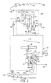
- FIG. 2 schematically depicts the preferred embodiment of the present invention for a wing mounted aircraft gas turbine engine 10.
- the preferred embodiment includes a power supply means for an aircraft ECS using compressed air supplied by a gas turbine engine bleed means 54 from a midstage bleed line 43 or a compressor discharge bleed line 45 and an energy recovery means for returning the unrequired or unused amount of energy back to engine 10.
- the energy recovery means includes a starting air turbine 50 drivingly connected through a starter gearbox 48 and power takeoff shaft 47 to HP shaft 38.
- Starter gearbox 48 is preferably a planetary type gearbox so as to be able to efficiently receive and distribute power supplied to it by air turbine 50 and is conventionally integrated within the same casing or assembly (not shown) as air turbine 50.
- Air turbine 50 is preferably a single stage radial inflow air turbine having an air turbine inlet 57.
- Compressor bleed means 54 on engine 10 is connected in fluid supply communication by a compressor bleed duct 56 to air turbine inlet 57.
- a switchable starting air supply means 280 conventionally ducted to air turbine inlet 57 through a multi-function duct 70, provides sources of starting air including inflight sources such as crossbleed systems from other engines.
- Disposed in multi- function duct line 70 is a switchable staring air dump valve 77 having a overboard dump line 93.
- Air turbine 50 includes a variable vane inlet 57 to control the pressure of compressed engine bleed air supplied to ECS flow control valve 80.
- the energy recovery means further provides for control of variable vane inlet 57 which is maintained by closed loop controller 500 which responds to a differential pressure signal provided by ECS flow control valve 80.
- Closed loop controller 500 closes and opens variable vane inlet 57, like the iris on a camera lens, in order to prevent less than a preselected pressure differential, about 1 psid or as system requirements dictate, across ECS flow control valve 80.
- air turbine 50 operates as a conventional air starting turbine receiving compressed starting air from starting air supply 280. Starting air is then dumped overboard by starting air dump valve 77 through line 93. The power created from air turbine 50 cranks HPT shaft 38 through starter gearbox 48 until engine 10 is capable of continuing operation without assist from air turbine 50. At this point of the engine's operation air turbine 50 continues to operate off of the compressor air supplied from compressor bleed means 54 unlike conventional starters which employ some sort of clutch mechanism after engine start to disconnect the starting turbine. Starting air valve 77 is then returned to a position which allows compressor bleed air to reach ECS pack 100.
- an aircraft nacelle boundary layer bleed means having a nacelle boundary layer bleed means 216 including a perforated skin 214 surrounds a forward nacelle portion 220 having disposed within a nacelle plenum 210 for bleeding a portion of the boundary layer from the forward portion of the nacelle 220 which extends aft from about the nacelle leading edge 218.
- Nacelle plenum 210 is ducted to a nacelle boundary layer compressor 60 via nacelle bleed duct 230.
- Nacelle boundary layer compressor 60 is drivenly connected to air turbine 50 preferably on a common rotor or shaft 52 and maybe integrally mounted within a common casing with air turbine 50 so as to form a staring air and aircraft boundary layer bleed turbocompressor.
- boundary layer compressor 60 is a centrifugal compressor having a nacelle boundary layer bleed inlet 62 and outlet 64 which dumps to a low pressure region of the engine 66 such as in the fan bypass duct 13, schematically depicted in FIG. 1, where it may be used for thrust and reduction of localized fan duct base pressure drag.
- FIG. 5 shows, in greater detail, one low pressure region 518 of fan duct 13 of particular note.
- FIG. 5 shows engine 10 having a fan section 12 including fan blades 14 circumscribed by annular nacelle 200 which forms the radially outward wall of fan duct 13 aft of fan blades 14.
- Radially disposed within fan duct 13 in serial flow relationship are fan exit guide vanes exit guide vanes 508, struts 512, and pylon fairings 516 respectively.
- Pylon fairing 516 conventionally has an airfoil shaped cross section as is more particularly shown in FIG. 5A which shows a cross section AA, looking radially inward, of the pylon fairing 516 shown in FIG 5.
- the cross section more particularly points out the aerodynamic shape of pylon fairing 516 designed to reduce its drag thus giving it a thickened front end and a narrow thinned out aft end where the low pressure induced base pressure drag occurs.
- Low pressure region 518 lies in the thinned out aft section of airfoil shaped pylon fairing 516 which passes across fan duct 13.
- the boundary layer air is bled from the nacelles, wings, and tail assemblies, is ambient pressure air having a substantial velocity relative to the aircraft thereby causing the aircraft to incur a significant ram air drag penalty when the air and its momentum is taken on board.
- This compressed bleed air to reduce base pressure drag compensates, to some extent, the ram air drag penalty.
- Dumping this used bleed air in a low pressure region of the fan duct such as in the thin section 518 of pylon fairing 516 reduces base pressure drag, and produces some extra thrust so as to further compensate for the ram air drag penalty.
- a description and of low pressure induced base pressure drag may be found in the classical reference on the subject of drag, FLUID-DYNAMIC DRAG by Sighard Hoerner (particularly pages 3-18 to 3-20 and page 20-16), which is incorporated herein by reference.
- ECS pack 100 which has its various components depicted within the dotted rectangle in FIG. 2, is ducted to air turbine outlet 59 via a multi-function bleed duct 70 for receiving ECS bleed air.
- a multi-function bleed duct 70 conventionally also provides compressed starting air to the starting air turbine 50 and anti-icing air when needed.
- Multi-function bleed duct 70 ducts ECS bleed air to primary heat exchanger 110 located in ECS pack 100 from where it is ducted to an ECS turbocompressor 125 via an ECS turbocompressor inlet duct 120 and used to power the ECS turbocompressor 125.
- ECS turbocompressor 125 includes an ECS compressor 130 which receives ECS bleed air from duct 120 and ducts it to a bleed air powered ECS turbine 150 via an intercooler duct 134 which first passes through a secondary heat exchanger 136 for the purpose of intercooling the ECS bleed air after it has been compressed by ECS compressor 130.
- the ECS bleed air is expanded through ECS turbine 150 to power the ECS turbine and cool the ECS bleed air and subsequently ducted to the aircraft cabin 167.
- ECS turbine 150 is mounted in driving relationship on a common turbocompressor shaft or rotor 162 with ECS compressor 130 and an ECS cooling fan 132.
- the preferred embodiment further provides a wing boundary layer bleed means 185 including a forward wing portion 190 of aircraft wing 180 wherein the forward portion is covered with a perforated wing skin 194 disposed about a wing plenum 180 which exhausts to ECS cooling duct 300 which passes through and provides the cooling air for secondary heat exchanger 136 and primary heat exchanger 110.
- ECS cooling fan 132 driven by ECS turbine 150, draws the boundary layer off the wing as opposed to being unused in a conventional system wherein air scoops on the outside of the aircraft use ram air to cool the heat exchangers.
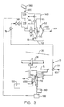
- FIG. 3 does not include either the nacelle or the wing boundary layer bleed features of the embodiment in FIG. 2 and incorporates a conventional aircraft cooling air scoop to gather cooling air for heat exchangers 110 and 136 in ECS pack 100.
- a speed control means 550 which may be electronic, mechanical, or hydraulic in operation and either automatically or manually controlled, provides the proper switching of gear ratios for two speed drive 400 thus allowing turbine 50 to operate at two different gear ratios with respect to HP shaft 38.
- a two speed, preferably clutch operated, drive 400 is schematically shown located between air turbine 50 and gearbox 48 so as to allow air turbine 50 to operate at two different gear ratios with respect to HP shaft 38 corresponding to engine start-up and running conditions respectively.
- Drive 400 is preferably a planetary gear type drive or gearbox and the clutch is preferably integrated into the planetary gearbox assembly.
- air turbine 50 continues to operate after engine start-up is complete and provides multiple functions and capabilities not found in conventional aircraft gas turbine engines.
- Starting air turbine 50 expands and therefore cools the compressor bleed air received from compressor bleed means 54 thereby reducing or eliminating the need for a bleed air precooler as found in conventional ECS systems if the system is properly sized and designed.
- FIG. 4 adds, to the preferred embodiment shown in FIG. 2, a fan powered compressor bleed air precooler 71 which requires little or no fan powered cooling air under most conditions but is included for those portions of the engine's flight envelope where it may be required or beneficial.
- a substantial reduction in specific fuel consumption may be accomplished by reducing or eliminating the use of fan air for compressor bleed air precooling over a substantial portion of the aircraft gas turbine engine's operational envelope.
- a fan bleed air duct 73 also shown in FIG. 1, ducts pressurized cooling air through compressor bleed air precooler 71, where it cools the compressor bleed air in compressor bleed air duct 70 being ducted to ECS pack 100, before being dumped through dump line 74.
- FIG. 6 contemplates bleeding boundary layer air from the airfoil structures of the tail assembly of an aircraft, such as the McDonnell Douglas DC-10 or MD-11, having a tail mounted engine.
- Such an embodiment would include the nacelle mounted engine and use the same ECS packs of FIG. 2 but without the wing boundary bleed system since the engine is not mounted near a wing.
- the embodiment includes the nacelle boundary bleed system 216 including air turbine 50 which drives nacelle boundary bleed compressor 60 as shown in FIG 2.
- the aircraft 610 includes a tail assembly 620 having a tail engine nacelle 624, a horizontal stabilizers 632 and vertical stabilizer 630.
- the tail engine nacelle 624 contains a gas turbine engine as in FIG.
- Nacelle 624 and stabilizers 630 and 632 each have respective perforated skin covered forward portions 638 of the stabilizers and 640 of the tail engine nacelle.
- the nacelle boundary layer bleed compressor 60 depicted in FIG 2 is used to bleed air boundary layer air for the tail engine nacelle 624, vertical stabilizer 630, and horizontal stabilizers 632 through perforations 646 through an integrated series of flowpaths and plenums (not shown) beneath the perforated skins. It is contemplated that the plenums beneath the stabilizers would have flowpaths connected to a tail engine nacelle plenum and associated nacelle boundary layer bleed system similar to that shown in FIG. 2.
- the described embodiments provide a distinct advantage for improving specific fuel consumption by returning otherwise unused energy to the engine and using the starting air turbine and ECS pack to reduce drag on the nacelles, wings, and tail assemblies by bleeding off boundary layer air.
- Sample calculations to determine the magnitude of the advantages that can be realized from the present invention were made based on the following presumptions. Typical Boeing 767-300 and McDonnell Douglas MD-11 aircraft having two and three General Electric CF6-80C2 engines respectively and passenger loads of 261 and 348 people respectively and for operating conditions at a 35,000 foot (10,700 m) cruising altitude at a point where the engines are operating at thrust levels of 8400 and 8600 pounds (3660 and 3900 kg) respectively.
- the return of the unused energy in the compressor bleed flow represents a calculated reduction of .68% and .52% in specific fuel consumption for each respective engine and the nacelle boundary layer bleed means contributes approximately an additional reduction of 0.79% and 0.8% in specific fuel consumption per engine respectively.
- the wing boundary layer bleed means contributes a calculated reduction of 1.6% per aircraft or .8% per wing mounted engine in specific fuel consumption.
- the total projected reduction in specific fuel consumption is over 2% per aircraft, representing a significant fuel savings to the aircraft operators.
- the described engine has a quick and reliable in flight restart or relight capability, with a starter that avoids the need for crash engagement for in flight relight.
- Aircraft boundary layer drag is reduced in a fuel efficient manner by using boundary layer bleed air to reduce base pressure drag in low pressure regions of the aircraft engine fan duct.
Abstract
Description
- The invention relates to aircraft environmental control systems powered by gas turbine engines for supplying aircraft system bleed air. In particular, the invention relates to an aircraft gas turbine engine powered bleed air supply system for an environmental control system wherein the excess pressure energy is returned to the engine to improve fuel efficiency and the system is also used to reduce drag on engine nacelles or other surfaces by pumping boundary layer air. Environmental control systems, commonly referred to as ECS systems, incorporate various pieces of equipment such as turbocompressors, regulating valves, heat exchangers, and other devices in a system which is often referred to as and ECS pack to condition engine bleed air. Modern day jet aircraft use turbocompressors in their environmental controls systems to condition bleed air for use in the cabin wherein the turbocompressors are powered by the same bleed that is conditioned for cabin refreshing air and which is usually supplied by the gas turbine engines which provide aircraft propulsion. Bleed air is conventionally taken from the engine compressor at a stage downstream of the variable vane compressor stages so as not to interfere with the operation of the variable vane stages which greatly enhance the efficiency of the gas turbine engine and greatly reduces the specific fuel consumption (SFC) of the engine.
- The compressor bleed air is cooled by fan air in a heat exchanger and is then delivered to the environmental control system for controlling cabin air freshness, pressure, and temperature. The ECS conventionally includes two ECS packs mounted in ECS bays on different sides of the aircraft which receive compressor bleed air from the engines. The bleed after being used to power the ECS pack and refresh the cabin is then dumped overboard. All the energy remaining in the bleed air dumped overboard cost fuel and therefore represents a significant loss in specific fuel consumption.
- Extraction of aircraft bleed air from the engine compressor has adverse affects on the propulsion cycle and engine life. Engine turbine power is needed to compress air and account for compressor inefficiency. Therefore, extra fuel consumption is always associated with gas turbine engine compressor bleed air (air which does not produce thrust). This extra fuel burned in the engine combustor results in higher gas temperature delivered to the engine turbine and reduction of turbine blade life. Such penalties must be incurred in order that the engine turbine provide extra power associated with bleed air.
- It is not possible, without undue complexity, to always bleed the engine compressor stage which provides exactly the correct pressure needed for the aircraft anti-ice and ECS systems. Typically only two bleed ports are provided. Therefore, the result is to bleed air which exceeds minimum pressure requirements resulting in even higher penalty to the engine cycle than would be required by the aircraft systems.
- Most often the bleed air is not only at a higher than required pressure, it is also too hot. For reasons of fire safety, maximum bleed air temperature is usually limited to 350 to 500°F (177 to 260°C). Temperature control requires cooling the bleed air with a precooler. Most modern engines use fan air to cool compressor bleed air. Use of fan air imposes an additional penalty on fuel consumption. Further, the precooler is usually large and requires a fan air scoop which produces drag. A typical large turbofan engine will consume about 2% extra fuel and run at about 20°F (11°C) hotter turbine temperature in order to provide aircraft system bleed air. One aspect of the invention addresses these problems and deficiencies characteristic of the prior art and conventional apparatus used to supply aircraft bleed air.
- A second aspect of this invention concerns the engine air driven starter. Air starters are conventionally air powered turbines having planetary gearboxes which are usually connected to a high pressure rotor in driving relationship and mounted to the engine accessory gearbox. The starter turbine rotates at very high speed and drives the engine through a planetary gear system during engine acceleration to just below idle speed. Once the engine lights it begins to develop its own power and, at a speed below idle, accelerates away from the starter. An overrunning mechanical clutch allows the starter to disengage and then the starter air is shut off and the starter turbine comes to rest. During the remainder of the flight the starter is not used for any purpose and simply represents extra weight carried around by the aircraft.
- Within a very narrow flight profile of the aircraft, the starter can sometimes be used for emergency engine relight, but only at conditions where the windmill speed of the engine is low enough that the starter clutch can be engaged without damage due to what is referred to as crash engagement. Engine starters can not be used during normal aircraft cruise conditions where the only means for relight is from the freely windmilling engine. In this aspect of the invention it advantageously permits operation of the air starter during all aircraft flight conditions thereby avoiding the delay in engine relight which can be associated with flight conditions unfavorable for fast windmill relights. It can further enhance the solution to the relight problem by permitting use of the starter turbine during all operation conditions as a means for improving the performance of the auxiliary bleed air compressor.
- A third aspect of this invention relates to aerodynamic drag associated with engine nacelles, wings, pylons, tail sections and other aircraft outer surfaces. As air flows on to and over a surface such as an engine nacelle and aircraft wing it progressively builds up a low velocity boundary layer of increasing thickness. Within this boundary layer a portion of the velocity component of free stream total pressure is converted to increased static pressure. As the result of rise in static pressure, boundary layer thickness, and diffusion a point is reached where back pressure causes an otherwise laminar boundary layer to become turbulent.
- In the turbulent region, a considerable amount of total pressure is converted to static temperature represented thermodynamically as an increase in entropy. By the time the boundary layer leaves the surface, or in the particular case of an aircraft gas turbine engine the end of the nacelle, an unrecoverable loss in total pressure has occurred. The large entropy rise associated with turbulence is at the expense of air momentum. Turbulence also gives rise to increased static pressure which may increase the intensity of rearward acting pressure force on the surface. Now, if the boundary layer thickness is kept small, separation and turbulence will not occur or will be delayed and drag can be substantially reduced.
- One way to avoid increase in boundary thickness is to pump or bleed off boundary layer air through holes in the surface. Boundary layer pumps or compressors would be desirable from an aerodynamic standpoint but, because of the relatively large air flow rates and added weight and complexity associated with effective boundary layer pumping or bleeding, the concept has not been adapted in modern aircraft and engines. Therefore one embodiment of this invention provides a means for effectively and economically using the engine starting turbine to power a nacelle boundary layer bleed compressor to bleed off laminar flow boundary layer air from the nacelle to reduce drag. Yet another embodiment uses an ECS heat exchanger cooling fan to bleed off laminar flow boundary layer air from the wing to reduce drag.
- A similar problem was addressed in US patent application Serial No. 07/489,150 entitled "AIRCRAFT ENGINE STARTER INTEGRATED BOUNDARY BLEED SYSTEM" (inventor Samuel Davison) assigned to us and on which we have filed on 1 March 1991 a corresponding GB application no. 9104388.5, the disclosure in which is incorporated herein by reference. Bleed air taken into the engine compressor also incurs a ram drag penalty (loss of momentum). Engine net thrust is equal to engine exhaust momentum minus inlet ram drag.
- In summary, in accordance with one embodiment of the present invention, an environmental control system apparatus for an aircraft powered by a gas turbine engine is provided with an engine compressor bleed supply means and an energy recovery means for returning the unrequired or unused amount of energy back to the engine. The energy recovery means includes a starting air turbine mechanically linked in driving relationship through the starter air turbine's planetary gearbox to the high pressure rotor of the gas turbine engine wherein the air turbine includes a variable inlet and a means to control it which is in switchable fluid supply communication with sources of compressed starting air and gas turbine engine compressor bleed air and provided with a means for ducting its exhaust flow to an environmental control system pack ECS compressor. The ECS includes a means for producing a pressure differential signal which is provided to the variable inlet control means for controlling the variable inlet.
- Another embodiment of the invention provides an auxiliary compressor drivingly linked to the starting air turbine, preferably on a common shaft, and having an inlet in fluid communication with a means for bleeding a portion of the boundary layer air from the outer surface of the nacelle.
- Yet another embodiment includes an ECS heat exchanger cooling fan driven by the turbine of the ECS turbocompressor wherein the ECS fan includes an inlet in fluid communication with a means for bleeding a portion of the boundary layer air from a forward portion of the outer surface of the aircraft wing.
- According to another embodiment of the present invention the means for bleeding a portion of the boundary layer air from a forward portion of the outer surface of the aircraft wing or nacelle includes a perforated outer skin connected to an annular plenum below the perforated skin.
- And another embodiment includes a means for dumping the boundary layer bleed air into a low pressure region of the fan duct that produces base pressure drag on the engine such as the aft end of the pylon fairing.
- Other features and advantages of embodiments of the invention will become more readily apparent in the following description when taken in conjunction with the appended drawings, in which:
- FIG. 1 is a schematic representation of an aircraft dual rotor gas turbine engine.
- FIG. 2 is a schematic representation of the preferred embodiment of the gas turbine engine powered aircraft environmental control system and aircraft boundary layer bleed of the present invention.
- FIG. 3 is a schematic representation of the an alternate embodiment of the present invention as shown in FIG. 2 without the aircraft boundary layer bleed features.
- FIG. 4 is a schematic representation of the an alternate embodiment of the present invention as shown in FIG. 3 which includes an engine fan supplied precooler to precool the bleed air for the ECS.
- FIG. 5 is a cutaway perspective drawing of an aircraft engine fan duct.
- FIG. 5a is a cross section AA taken through the pylon fairing in FIG. 5 looking radially inward toward the engine.
- FIG. 6 is a perspective view of a tail assembly of an aircraft having a tail engine mounted in a tail engine nacelle.
- FIG. 1 illustrates a typical
gas turbine engine 10 having in serial flow relationship afan section 12, a low pressure compressor (LPC) 16, a high pressure compressor (HPC) 20, acombustion section 24, a high pressure turbine (HPT) 30, and a low pressure turbine (LPT) 34. Ahigh pressure rotor 31 includes high pressure (HP)shaft 38 which connects, in drivingrelationship HPT 30 toHPC 20 and alow pressure rotor 35 includes alow pressure shaft 42 disposed within high pressure (LP)shaft 38 which drivingly connectsLPT 34 toLPC 16 andfan 12. Apower takeoff shaft 47 drivingly connectsHP shaft 38 tostarter gearbox 48 through atransfer gearbox 38 depicted by the 45 degree bevel gears in FIG. 1. - A compressor bleed means 54, in FIG. 1, includes a mid
compressor bleed line 43, preferably a seventh stage bleed for a General Electric CF6-80C2, and a compressordischarge bleed line 45 manifolded together and ducted out ofHPC 20 by acompressor bleed duct 56. Disposed in midcompressor bleed line 43 is acheck valve 44 which prevents higher pressure air from compressordischarge bleed line 45, which has a pressure actuatedshutoff valve 46 disposed in it, flowing into a midstage of the compressor. During idle operation of thegas turbine engine 10 air from compressordischarge bleed line 45 is used and during the rest of the engine's operation compressor bleed air is supplied from midcompressor bleed line 43 to compressor bleedduct 56. - FIG. 2 schematically depicts the preferred embodiment of the present invention for a wing mounted aircraft
gas turbine engine 10. The preferred embodiment includes a power supply means for an aircraft ECS using compressed air supplied by a gas turbine engine bleed means 54 from amidstage bleed line 43 or a compressordischarge bleed line 45 and an energy recovery means for returning the unrequired or unused amount of energy back toengine 10. The energy recovery means includes a startingair turbine 50 drivingly connected through astarter gearbox 48 andpower takeoff shaft 47 toHP shaft 38.Starter gearbox 48 is preferably a planetary type gearbox so as to be able to efficiently receive and distribute power supplied to it byair turbine 50 and is conventionally integrated within the same casing or assembly (not shown) asair turbine 50. -
Air turbine 50 is preferably a single stage radial inflow air turbine having anair turbine inlet 57. Compressor bleed means 54 onengine 10 is connected in fluid supply communication by acompressor bleed duct 56 toair turbine inlet 57. A switchable starting air supply means 280, conventionally ducted toair turbine inlet 57 through amulti-function duct 70, provides sources of starting air including inflight sources such as crossbleed systems from other engines. Disposed in multi-function duct line 70 is a switchable staringair dump valve 77 having aoverboard dump line 93. -
Air turbine 50 includes avariable vane inlet 57 to control the pressure of compressed engine bleed air supplied to ECSflow control valve 80. The energy recovery means further provides for control ofvariable vane inlet 57 which is maintained byclosed loop controller 500 which responds to a differential pressure signal provided by ECSflow control valve 80.Closed loop controller 500 closes and opensvariable vane inlet 57, like the iris on a camera lens, in order to prevent less than a preselected pressure differential, about 1 psid or as system requirements dictate, across ECSflow control valve 80. - During engine ground start operation of the invention illustrated in FIGS. 1 and 2
air turbine 50 operates as a conventional air starting turbine receiving compressed starting air from startingair supply 280. Starting air is then dumped overboard by startingair dump valve 77 throughline 93. The power created fromair turbine 50cranks HPT shaft 38 throughstarter gearbox 48 untilengine 10 is capable of continuing operation without assist fromair turbine 50. At this point of the engine'soperation air turbine 50 continues to operate off of the compressor air supplied from compressor bleed means 54 unlike conventional starters which employ some sort of clutch mechanism after engine start to disconnect the starting turbine. Startingair valve 77 is then returned to a position which allows compressor bleed air to reachECS pack 100. - The preferred embodiment, as shown in FIG. 2 is provided with an aircraft nacelle boundary layer bleed means having a nacelle boundary layer bleed means 216 including a
perforated skin 214 surrounds aforward nacelle portion 220 having disposed within anacelle plenum 210 for bleeding a portion of the boundary layer from the forward portion of thenacelle 220 which extends aft from about thenacelle leading edge 218.Nacelle plenum 210 is ducted to a nacelleboundary layer compressor 60 vianacelle bleed duct 230. Nacelleboundary layer compressor 60 is drivenly connected toair turbine 50 preferably on a common rotor orshaft 52 and maybe integrally mounted within a common casing withair turbine 50 so as to form a staring air and aircraft boundary layer bleed turbocompressor. In the preferred embodiment,boundary layer compressor 60 is a centrifugal compressor having a nacelle boundary layer bleedinlet 62 andoutlet 64 which dumps to a low pressure region of theengine 66 such as in thefan bypass duct 13, schematically depicted in FIG. 1, where it may be used for thrust and reduction of localized fan duct base pressure drag. - FIG. 5 shows, in greater detail, one
low pressure region 518 offan duct 13 of particular note. FIG. 5 showsengine 10 having afan section 12 includingfan blades 14 circumscribed byannular nacelle 200 which forms the radially outward wall offan duct 13 aft offan blades 14. Radially disposed withinfan duct 13 in serial flow relationship are fan exit guide vanes exitguide vanes 508, struts 512, andpylon fairings 516 respectively. Pylon fairing 516 conventionally has an airfoil shaped cross section as is more particularly shown in FIG. 5A which shows a cross section AA, looking radially inward, of the pylon fairing 516 shown in FIG 5. The cross section more particularly points out the aerodynamic shape of pylon fairing 516 designed to reduce its drag thus giving it a thickened front end and a narrow thinned out aft end where the low pressure induced base pressure drag occurs.Low pressure region 518 lies in the thinned out aft section of airfoil shaped pylon fairing 516 which passes acrossfan duct 13. - The boundary layer air is bled from the nacelles, wings, and tail assemblies, is ambient pressure air having a substantial velocity relative to the aircraft thereby causing the aircraft to incur a significant ram air drag penalty when the air and its momentum is taken on board. Using this compressed bleed air to reduce base pressure drag compensates, to some extent, the ram air drag penalty. Dumping this used bleed air in a low pressure region of the fan duct such as in the
thin section 518 of pylon fairing 516 reduces base pressure drag, and produces some extra thrust so as to further compensate for the ram air drag penalty. A description and of low pressure induced base pressure drag may be found in the classical reference on the subject of drag, FLUID-DYNAMIC DRAG by Sighard Hoerner (particularly pages 3-18 to 3-20 and page 20-16), which is incorporated herein by reference. -
ECS pack 100, which has its various components depicted within the dotted rectangle in FIG. 2, is ducted toair turbine outlet 59 via amulti-function bleed duct 70 for receiving ECS bleed air. Amulti-function bleed duct 70 conventionally also provides compressed starting air to the startingair turbine 50 and anti-icing air when needed. Operably disposed inmulti-function bleed duct 70, in serial flow relationship, is apressure regulating valve 76 used to limit the pressure withinmulti-function bleed duct 70 and aflow control valve 80 used to measure the amount and adjust the pressure of the bleed flow to theECS pack 100. -
Multi-function bleed duct 70 ducts ECS bleed air toprimary heat exchanger 110 located inECS pack 100 from where it is ducted to anECS turbocompressor 125 via an ECSturbocompressor inlet duct 120 and used to power theECS turbocompressor 125. Although in the preferred embodiment there should be no need for an engine compressor bleed air precooler, ifair turbine 50 can be sized properly to provide, through expansion, all the cooling required of the engine compressor bleed air ducted throughduct 70, there may be designs that require some precooling that may be provided by such a precooler as depicted in an alternate embodiment shown in FIG. 4 and explained in further detail further on herein. -
ECS turbocompressor 125 includes anECS compressor 130 which receives ECS bleed air fromduct 120 and ducts it to a bleed air poweredECS turbine 150 via anintercooler duct 134 which first passes through asecondary heat exchanger 136 for the purpose of intercooling the ECS bleed air after it has been compressed byECS compressor 130. The ECS bleed air is expanded throughECS turbine 150 to power the ECS turbine and cool the ECS bleed air and subsequently ducted to theaircraft cabin 167.ECS turbine 150 is mounted in driving relationship on a common turbocompressor shaft orrotor 162 withECS compressor 130 and anECS cooling fan 132. - The preferred embodiment further provides a wing boundary layer bleed means 185 including a
forward wing portion 190 ofaircraft wing 180 wherein the forward portion is covered with aperforated wing skin 194 disposed about awing plenum 180 which exhausts toECS cooling duct 300 which passes through and provides the cooling air forsecondary heat exchanger 136 andprimary heat exchanger 110. During operationECS cooling fan 132, driven byECS turbine 150, draws the boundary layer off the wing as opposed to being unused in a conventional system wherein air scoops on the outside of the aircraft use ram air to cool the heat exchangers. There is therefore the added advantage of not requiring any additional rotating equipment such as a compressor to bleed a portion of the boundary off of the wing. This advantage significantly reduces any additional complexity or weight that might otherwise be added to the aircraft and its gas turbine engines. - Another embodiment is depicted in FIG. 3 does not include either the nacelle or the wing boundary layer bleed features of the embodiment in FIG. 2 and incorporates a conventional aircraft cooling air scoop to gather cooling air for
heat exchangers ECS pack 100. A speed control means 550, which may be electronic, mechanical, or hydraulic in operation and either automatically or manually controlled, provides the proper switching of gear ratios for twospeed drive 400 thus allowingturbine 50 to operate at two different gear ratios with respect toHP shaft 38. A two speed, preferably clutch operated, drive 400 is schematically shown located betweenair turbine 50 andgearbox 48 so as to allowair turbine 50 to operate at two different gear ratios with respect toHP shaft 38 corresponding to engine start-up and running conditions respectively. Drive 400 is preferably a planetary gear type drive or gearbox and the clutch is preferably integrated into the planetary gearbox assembly. - As illustrated in FIG. 2, the preferred embodiment of the present invention,
air turbine 50 continues to operate after engine start-up is complete and provides multiple functions and capabilities not found in conventional aircraft gas turbine engines. Startingair turbine 50 expands and therefore cools the compressor bleed air received from compressor bleed means 54 thereby reducing or eliminating the need for a bleed air precooler as found in conventional ECS systems if the system is properly sized and designed. - However, an alternate embodiment, shown in FIG. 4, adds, to the preferred embodiment shown in FIG. 2, a fan powered compressor
bleed air precooler 71 which requires little or no fan powered cooling air under most conditions but is included for those portions of the engine's flight envelope where it may be required or beneficial. Thus a substantial reduction in specific fuel consumption may be accomplished by reducing or eliminating the use of fan air for compressor bleed air precooling over a substantial portion of the aircraft gas turbine engine's operational envelope. Referring to FIG. 4, a fanbleed air duct 73, also shown in FIG. 1, ducts pressurized cooling air through compressorbleed air precooler 71, where it cools the compressor bleed air in compressor bleedair duct 70 being ducted toECS pack 100, before being dumped throughdump line 74. - An alternative embodiment shown in FIG. 6, contemplates bleeding boundary layer air from the airfoil structures of the tail assembly of an aircraft, such as the McDonnell Douglas DC-10 or MD-11, having a tail mounted engine. Such an embodiment would include the nacelle mounted engine and use the same ECS packs of FIG. 2 but without the wing boundary bleed system since the engine is not mounted near a wing. The embodiment includes the nacelle
boundary bleed system 216 includingair turbine 50 which drives nacelleboundary bleed compressor 60 as shown in FIG 2. Referring to FIG. 6, theaircraft 610 includes atail assembly 620 having atail engine nacelle 624, ahorizontal stabilizers 632 andvertical stabilizer 630. Thetail engine nacelle 624 contains a gas turbine engine as in FIG. 2 but without powered wing bleed system.Nacelle 624 andstabilizers portions 638 of the stabilizers and 640 of the tail engine nacelle. The nacelle boundarylayer bleed compressor 60 depicted in FIG 2 is used to bleed air boundary layer air for thetail engine nacelle 624,vertical stabilizer 630, andhorizontal stabilizers 632 throughperforations 646 through an integrated series of flowpaths and plenums (not shown) beneath the perforated skins. It is contemplated that the plenums beneath the stabilizers would have flowpaths connected to a tail engine nacelle plenum and associated nacelle boundary layer bleed system similar to that shown in FIG. 2. - The described embodiments provide a distinct advantage for improving specific fuel consumption by returning otherwise unused energy to the engine and using the starting air turbine and ECS pack to reduce drag on the nacelles, wings, and tail assemblies by bleeding off boundary layer air. Sample calculations to determine the magnitude of the advantages that can be realized from the present invention were made based on the following presumptions. Typical Boeing 767-300 and McDonnell Douglas MD-11 aircraft having two and three General Electric CF6-80C2 engines respectively and passenger loads of 261 and 348 people respectively and for operating conditions at a 35,000 foot (10,700 m) cruising altitude at a point where the engines are operating at thrust levels of 8400 and 8600 pounds (3660 and 3900 kg) respectively. The return of the unused energy in the compressor bleed flow represents a calculated reduction of .68% and .52% in specific fuel consumption for each respective engine and the nacelle boundary layer bleed means contributes approximately an additional reduction of 0.79% and 0.8% in specific fuel consumption per engine respectively. The wing boundary layer bleed means contributes a calculated reduction of 1.6% per aircraft or .8% per wing mounted engine in specific fuel consumption. The total projected reduction in specific fuel consumption is over 2% per aircraft, representing a significant fuel savings to the aircraft operators.
- There has thus been described herein a more efficient aircraft gas turbine engine which uses energy in the compressor bleed air that is conventionally wasted, while being lighter in weight and more efficient with a longer life.
- It eliminates the need for engine fan supplied cooling air for the ECS bleed air precooler, providing a fuel efficient system for supplying compressed air to the aircraft ECS systems.
- The described engine has a quick and reliable in flight restart or relight capability, with a starter that avoids the need for crash engagement for in flight relight.
- Aircraft boundary layer drag is reduced in a fuel efficient manner by using boundary layer bleed air to reduce base pressure drag in low pressure regions of the aircraft engine fan duct.
- The invention and its illustrated embodiments have been described in an illustrative manner. It is to be understood that the terminology which has been used is intended to be in the nature of words of description rather than of limitation. It is important to note the multifunctionality ascribed to many elements such as ducts, valves, fans, and compressors which provide the advantages of decreased engine and aircraft specific fuel consumption and lower aircraft drag. The invention contemplates using the energy recovery system and the wing, the nacelle, and the combination nacelle and tail assembly boundary layer bleed systems individually as well as in combination in various embodiments.
- Obviously, many modifications and variations are possible in light of the above teachings. It is, therefore, to be understood that the invention may be practised otherwise than as specifically described.
Claims (14)
- A gas turbine engine power supply apparatus for an aircraft environmental control system comprising: a bleed air means to bleed compressor bleed air from the gas turbine engine;
an energy recovery means comprising an energy extraction and work conversion means in fluid supply communication with said bleed air means effective for extracting energy from the bleed air supplied by said bleed air means and converting the extracted energy to useful work and a work transmission means to return the work from said energy to work conversion means to the engine; and
an environmental control system duct in fluid supply communication with said energy extraction and work conversion means to supply bleed air exhaust from said energy extraction and work conversion means energy to the environmental control system. - A gas turbine engine power supply apparatus for an aircraft environmental control system as claimed in claim 1 wherein said energy extraction and work conversion means comprises a starting air turbine.
- A gas turbine engine power supply apparatus for an aircraft environmental control system as claimed in claim 2 wherein said work transmission means comprises a shaft means connecting said air turbine in driving relationship through an starter gearbox to a rotor in the engine.
- A gas turbine engine power supply apparatus for an aircraft environmental control system as claimed in claim 3 wherein said air turbine includes a variable inlet and the apparatus includes an air turbine variable inlet control means to control the operation of said variable inlet.
- A gas turbine engine power supply apparatus for an aircraft environmental control system as claimed in claim 4 wherein said air turbine variable inlet control means controls said air turbine variable inlet in response to s differential pressure signal produced by an ECS flow control valve in the ECS system which measures a differential pressure across said ECS control valve and throttles bleed air flow to the ECS system.
- A gas turbine engine power supply apparatus for an aircraft environmental control system as claimed in claim 5 wherein said work transmission means is a planetary gear type including a two speed drive effective for changing the gear ratio and relative operating speeds between said engine rotor and said air turbine.
- A gas turbine engine power supply apparatus for an aircraft environmental control system as claimed in claim 6 wherein said air turbine is a starting air turbine and includes an air turbine inlet in switchable fluid supply communication with a means for supplying compressed starting air.
- An environmental control system (ECS) and aircraft boundary layer bleed system gas turbine engine powered apparatus for an aircraft, said apparatus comprising:
a bleed air means to bleed compressor bleed air from a compressor stage of the gas turbine engine,
a starting air turbine in fluid supply communication with said bleed air means effective for extracting energy from the bleed air supplied by said bleed air means and converting the extracted energy to useful work,
a work transmission means operably connected to said starting air turbine effective to return the work from said air turbine to the engine, a first bleed duct in fluid supply communication with said energy extraction and work conversion means to supply bleed air exhaust from said air turbine to a means for conditioning cabin air for an aircraft, and
at least one means for bleeding boundary layer air from the surface of the aircraft. - An apparatus as claimed in claim 8 wherein said means for bleeding boundary layer air includes a nacelle boundary layer bleed means comprising; a perforated skin surrounding a forward nacelle portion having a nacelle plenum disposed within; a nacelle bleed duct connecting, in fluid supply communication, said nacelle plenum to an inlet of a boundary layer compressor drivenly linked to said air turbine.
- An apparatus as claimed in claim 9 wherein said boundary layer compressor and said air turbine are mounted on a common shaft and said transmission means comprises a shaft means including said common shaft connecting said air turbine in driving relationship through an starter gearbox to a rotor in the engine.
- An apparatus as claimed in claim 8 wherein said means for bleeding boundary layer air includes a wing boundary layer bleed means comprising;
a perforated skin surrounding a forward wing portion having a wing plenum disposed within; and
an ECS cooling duct connected, in fluid supply communication, said wing plenum to an inlet of an ECS cooling fan drivenly linked to an ECS turbine. - An apparatus as claimed in claim 9 wherein said means for bleeding boundary layer air includes a wing boundary layer bleed means comprising;
a perforated skin surrounding a forward wing portion having a wing plenum disposed within; and
an ECS cooling duct connected, in fluid supply communication, said wing plenum to an inlet of an ECS cooling fan drivenly linked to an ECS turbine. - An apparatus as claimed in claim 9 or claim 10 wherein said nacelle is a tail engine nacelle and said apparatus further comprises a tail assembly boundary layer bleed means including a horizontal stabilizer boundary layer bleed means and vertical stabilizer boundary layer bleed means in fluid communication with said nacelle plenum.
- An apparatus as claimed in claims 9, 10, or 13 further comprising a low pressure base pressure drag producing region of a fan duct in said gas turbine engine and a means for introducing the boundary layer air bled by said means for bleeding boundary layer air into said low pressure base pressure drag producing region of a fan duct.
Applications Claiming Priority (2)
| Application Number | Priority Date | Filing Date | Title |
|---|---|---|---|
| US07/531,718 US5125597A (en) | 1990-06-01 | 1990-06-01 | Gas turbine engine powered aircraft environmental control system and boundary layer bleed with energy recovery system |
| US531718 | 2000-03-21 |
Publications (2)
| Publication Number | Publication Date |
|---|---|
| EP0459816A1 true EP0459816A1 (en) | 1991-12-04 |
| EP0459816B1 EP0459816B1 (en) | 1994-11-30 |
Family
ID=24118763
Family Applications (1)
| Application Number | Title | Priority Date | Filing Date |
|---|---|---|---|
| EP91304926A Expired - Lifetime EP0459816B1 (en) | 1990-06-01 | 1991-05-31 | Gas turbine engine powered aircraft environmental control system and boundary layer bleed |
Country Status (6)
| Country | Link |
|---|---|
| US (1) | US5125597A (en) |
| EP (1) | EP0459816B1 (en) |
| JP (1) | JP2533988B2 (en) |
| CA (1) | CA2042201A1 (en) |
| DE (1) | DE69105354T2 (en) |
| IL (1) | IL98194A0 (en) |
Cited By (12)
| Publication number | Priority date | Publication date | Assignee | Title |
|---|---|---|---|---|
| EP0517459A1 (en) * | 1991-06-04 | 1992-12-09 | General Electric Company | Aircraft gas turbine engine bleed air energy recovery apparatus |
| EP0657351A1 (en) * | 1993-12-09 | 1995-06-14 | AlliedSignal Inc. | Fully integrated environmental and secondary power system |
| EP1329382A2 (en) * | 2002-01-16 | 2003-07-23 | United Technologies Corporation | Engine integrated auxiliary power unit |
| GB2421281A (en) * | 2004-12-16 | 2006-06-21 | Rolls Royce Plc | Starting and anti-icing in a gas turbine engine |
| EP1728990A2 (en) * | 2005-06-02 | 2006-12-06 | General Electric Company | Auxiliary power unit supplied with air from the gas turbine |
| US7334423B2 (en) * | 2004-09-22 | 2008-02-26 | Hamilton Sundstrand Corporation | Dual mode condensing cycle |
| EP2128404A2 (en) * | 2008-05-21 | 2009-12-02 | Honeywell International Inc. | Gas turbine drive system for auxiliaries with lock-up clutch |
| WO2012045864A1 (en) * | 2010-10-08 | 2012-04-12 | Airbus Operations Gmbh | Main engine start by means of an aircraft air conditioning system |
| WO2012175883A1 (en) * | 2011-06-22 | 2012-12-27 | Snecma | Ventilation of an accessory gear box, and turbojet engine comprising such a gear box |
| WO2013079100A1 (en) * | 2011-11-29 | 2013-06-06 | Short Brothers Plc | System and method for cooling an aircraft wing |
| WO2015183360A3 (en) * | 2014-03-04 | 2016-01-14 | Parker-Hannifin Corporation | Laminar flow control with integrated heat exchanger for an aircraft |
| US11208950B2 (en) | 2012-01-31 | 2021-12-28 | Raytheon Technologies Corporation | Gas turbine engine with compressor inlet guide vane positioned for starting |
Families Citing this family (55)
| Publication number | Priority date | Publication date | Assignee | Title |
|---|---|---|---|---|
| US5363641A (en) * | 1993-08-06 | 1994-11-15 | United Technologies Corporation | Integrated auxiliary power system |
| DE19643069C2 (en) * | 1996-10-18 | 1999-03-25 | Daimler Benz Aerospace Airbus | Vertical tail structure for an aircraft |
| US5911388A (en) * | 1997-01-15 | 1999-06-15 | Sundstrand Corporation | Environmental control system with energy recovery and bleed air assist |
| US5967461A (en) * | 1997-07-02 | 1999-10-19 | Mcdonnell Douglas Corp. | High efficiency environmental control systems and methods |
| US6305156B1 (en) | 1999-09-03 | 2001-10-23 | Alliedsignal Inc. | Integrated bleed air and engine starting system |
| US6920748B2 (en) * | 2002-07-03 | 2005-07-26 | General Electric Company | Methods and apparatus for operating gas turbine engines |
| US6990797B2 (en) * | 2003-09-05 | 2006-01-31 | General Electric Company | Methods and apparatus for operating gas turbine engines |
| US7055330B2 (en) * | 2004-02-25 | 2006-06-06 | United Technologies Corp | Apparatus for driving an accessory gearbox in a gas turbine engine |
| US8347647B2 (en) * | 2004-09-22 | 2013-01-08 | Hamilton Sundstrand Corporation | Air cycle machine for an aircraft environmental control system |
| US7757502B2 (en) * | 2004-09-22 | 2010-07-20 | Hamilton Sundstrand Corporation | RAM fan system for an aircraft environmental control system |
| US7380749B2 (en) * | 2005-04-21 | 2008-06-03 | The Boeing Company | Combined fuel cell aircraft auxiliary power unit and environmental control system |
| FR2913402B1 (en) * | 2007-03-07 | 2009-11-27 | Airbus France | AIRCRAFT HAVING AN AIR CONDITIONING SYSTEM. |
| US9157368B2 (en) * | 2007-09-05 | 2015-10-13 | United Technologies Corporation | Active flow control for nacelle inlet |
| US8132758B2 (en) * | 2008-03-12 | 2012-03-13 | Hamilton Sundstrand Corporation | Environmental control system pack pallets |
| US9057553B1 (en) * | 2008-03-14 | 2015-06-16 | MJC, Inc. | Dual pass air conditioning unit |
| US8146862B2 (en) * | 2008-06-13 | 2012-04-03 | Raytheon Company | Active vortex control system (AVOCS) method for isolation of sensitive components from external environments |
| US8266889B2 (en) * | 2008-08-25 | 2012-09-18 | General Electric Company | Gas turbine engine fan bleed heat exchanger system |
| US8432440B2 (en) * | 2009-02-27 | 2013-04-30 | General Electric Company | System and method for adjusting engine parameters based on flame visualization |
| US8063501B2 (en) * | 2009-06-10 | 2011-11-22 | Hamilton Sundstrand Corporation | Gas turbine bleed energy recovery via counter rotating generator |
| US8475114B2 (en) * | 2010-02-08 | 2013-07-02 | Hamilton Sundstrand Corporation | Air cycle machine air bearing shaft |
| US20130040545A1 (en) * | 2011-08-11 | 2013-02-14 | Hamilton Sundstrand Corporation | Low pressure compressor bleed exit for an aircraft pressurization system |
| US9470153B2 (en) * | 2011-10-05 | 2016-10-18 | United Technologies Corporation | Combined pump system for engine TMS AOC reduction and ECS loss elimination |
| US8978352B2 (en) * | 2011-10-21 | 2015-03-17 | United Technologies Corporation | Apparatus and method for operating a gas turbine engine during windmilling |
| US8966875B2 (en) * | 2011-10-21 | 2015-03-03 | United Technologies Corporation | Constant speed transmission for gas turbine engine |
| US8978351B2 (en) * | 2011-10-21 | 2015-03-17 | United Technologies Corporation | Integrated thermal management system and environmental control system for a gas turbine engine |
| US8966876B2 (en) * | 2011-10-21 | 2015-03-03 | United Technologies Corporation | Controllable speed windmill operation of a gas turbine engine through low spool power extraction |
| US9140188B2 (en) * | 2011-10-25 | 2015-09-22 | United Technologies Corporation | Gas turbine engine with intercooling turbine section |
| US8935923B2 (en) * | 2011-10-25 | 2015-01-20 | United Technologies Corporation | Gas turbine engine with intercooling turbine section and intercooling turbine section bypass |
| KR101294146B1 (en) * | 2011-11-28 | 2013-08-16 | 한국항공우주연구원 | Auxiliary power unit and auxiliary starting apparatus including the same |
| WO2014030024A1 (en) | 2012-08-22 | 2014-02-27 | Bombardier Inc. | Pre-cooler system with bypass valve, controller therefor, method and aircraft using the same |
| US9701399B1 (en) | 2013-03-18 | 2017-07-11 | Techdyne Llc | Parasitic drag induced boundary layer reduction system and method |
| US9341121B2 (en) * | 2013-12-13 | 2016-05-17 | United Technologies Corporation | Gas turbine engine with intercooling turbine section and intercooling turbine section bypass |
| FR3017159B1 (en) * | 2014-01-31 | 2016-03-04 | Snecma | AIR SUPPLYING AN AIR CONDITIONING CIRCUIT OF A CABIN OF AN AIRCRAFT FROM ITS TURBOPROPULSOR |
| CN106573680B (en) | 2014-07-03 | 2020-12-15 | 通用电气公司 | Cold air cooling system of jet engine |
| EP2995553B1 (en) * | 2014-09-09 | 2017-02-01 | Airbus Defence and Space GmbH | Air generation unit for an aircraft and method for its operation |
| US10371055B2 (en) * | 2015-02-12 | 2019-08-06 | United Technologies Corporation | Intercooled cooling air using cooling compressor as starter |
| US9989030B2 (en) | 2015-03-24 | 2018-06-05 | Ingersoll-Rand Company | Fluid powered starter with a variable turbine stator |
| US10273883B2 (en) * | 2016-02-26 | 2019-04-30 | The Boeing Company | Engine accessory drives systems and methods |
| EP4019403A1 (en) | 2016-05-26 | 2022-06-29 | Hamilton Sundstrand Corporation | Mixing ram and bleed air in a dual entry turbine system |
| US11506121B2 (en) * | 2016-05-26 | 2022-11-22 | Hamilton Sundstrand Corporation | Multiple nozzle configurations for a turbine of an environmental control system |
| US11105340B2 (en) | 2016-08-19 | 2021-08-31 | General Electric Company | Thermal management system for an electric propulsion engine |
| US10800539B2 (en) * | 2016-08-19 | 2020-10-13 | General Electric Company | Propulsion engine for an aircraft |
| US10676205B2 (en) | 2016-08-19 | 2020-06-09 | General Electric Company | Propulsion engine for an aircraft |
| US10221773B2 (en) | 2016-10-07 | 2019-03-05 | General Electric Company | Bleed valve assembly for a gas turbine engine |
| US10233845B2 (en) | 2016-10-07 | 2019-03-19 | General Electric Company | Bleed valve assembly for a gas turbine engine |
| US10208675B2 (en) * | 2017-03-15 | 2019-02-19 | The Boeing Company | Hybrid drive system for transferring power from a gas turbine engine of an aircraft |
| DE102018206428A1 (en) * | 2018-04-25 | 2019-10-31 | Deutsches Zentrum für Luft- und Raumfahrt e.V. | Method of using boundary layer extraction in a missile |
| US11156128B2 (en) | 2018-08-22 | 2021-10-26 | General Electric Company | Embedded electric machine |
| JP6947313B2 (en) * | 2018-11-06 | 2021-10-13 | 株式会社Ihi | Air conditioner for aircraft |
| US11713126B2 (en) | 2019-08-12 | 2023-08-01 | The Boeing Company | Aircraft air conditioning pack assembly and method of assembling |
| EP3789603A1 (en) * | 2019-08-12 | 2021-03-10 | Raytheon Technologies Corporation | Electric power assist for in-flight engine re-start |
| CN112601700A (en) * | 2019-09-30 | 2021-04-02 | 株式会社雅西玛技术 | Engine starting device |
| US20230407794A1 (en) * | 2020-10-28 | 2023-12-21 | Kawasaki Jukogyo Kabushiki Kaisha | Gas turbine engine for use in aircraft |
| US11913377B2 (en) * | 2022-02-18 | 2024-02-27 | Rtx Corporation | Environmental control systems |
| US20240076033A1 (en) * | 2022-09-02 | 2024-03-07 | Raytheon Technologies Corporation | Aerial vehicle fluid control system integrated with gas turbine engine |
Citations (9)
| Publication number | Priority date | Publication date | Assignee | Title |
|---|---|---|---|---|
| GB774695A (en) * | 1954-04-26 | 1957-05-15 | Rolls Royce | Improvements relating to internal combustion engines |
| GB846358A (en) * | 1957-06-12 | 1960-08-31 | Garrett Corp | Combination engine starter and accessory drive apparatus |
| US3024624A (en) * | 1958-09-04 | 1962-03-13 | Rolls Royce | Aircraft and turbine operated auxiliary equipment |
| US3428242A (en) * | 1967-06-02 | 1969-02-18 | United Aircraft Corp | Unitary simple/bootstrap air cycle system |
| US3878677A (en) * | 1974-04-10 | 1975-04-22 | United Aircraft Corp | Auxiliary turbine/compressor system for turbine engine |
| GB2074654A (en) * | 1980-04-16 | 1981-11-04 | Rolls Royce | Remote power system for aircraft |
| EP0065855A1 (en) * | 1981-05-26 | 1982-12-01 | LUCAS INDUSTRIES public limited company | Auxiliary power system for use with a gas turbine engine |
| GB2127492A (en) * | 1982-09-23 | 1984-04-11 | Rockwell International Corp | Integrated auxiliary power and environmental control unit |
| US4503666A (en) * | 1983-05-16 | 1985-03-12 | Rockwell International Corporation | Aircraft environmental control system with auxiliary power output |
Family Cites Families (38)
| Publication number | Priority date | Publication date | Assignee | Title |
|---|---|---|---|---|
| US2491462A (en) * | 1949-12-13 | Gas turbine driven air conditioning | ||
| US2734443A (en) * | 1956-02-14 | Enclosure air supply system | ||
| NL25885C (en) * | 1923-03-21 | |||
| GB585341A (en) * | 1942-09-10 | 1947-02-05 | Alan Arnold Griffith | Improvements in or relating to aircraft |
| US2777301A (en) * | 1952-06-30 | 1957-01-15 | Garrett Corp | All-purpose power and air conditioning system |
| US2728246A (en) * | 1953-02-02 | 1955-12-27 | Frank D Korkosz | Drive apparatus |
| GB743598A (en) * | 1953-04-15 | 1956-01-18 | Power Jets U Res And Developme | Aircraft boundary layer suction systems and compressors therefor |
| GB744923A (en) * | 1953-05-19 | 1956-02-15 | Rolls Royce | Improvements relating to gas turbine engines |
| US2771791A (en) * | 1954-12-13 | 1956-11-27 | Trans American Prec Instr Corp | Differential gearing apparatus |
| US2924991A (en) * | 1955-04-14 | 1960-02-16 | Lowell Taylor E | Speed-torque converter |
| US3307426A (en) * | 1960-01-11 | 1967-03-07 | Garrett Corp | Constant speed drive starter |
| GB1062631A (en) * | 1963-01-11 | 1967-03-22 | Plessey Uk Ltd | Improvements in or relating to composite hydromechanical constant-speed drives |
| US3260133A (en) * | 1964-04-13 | 1966-07-12 | Evert C Mattson | Controlled differential adjustable speed reversing drive system |
| US3525273A (en) * | 1968-01-23 | 1970-08-25 | Thomas Machine Inc | Differential drive mechanism |
| US3514945A (en) * | 1968-10-04 | 1970-06-02 | Avco Corp | Gas turbine accessory power drive unit |
| US3596524A (en) * | 1970-01-20 | 1971-08-03 | Trw Inc | Engine accessory drive system |
| US3711044A (en) * | 1971-03-17 | 1973-01-16 | Garrett Corp | Automatic interface control system |
| US3971210A (en) * | 1975-01-22 | 1976-07-27 | Dresser Industries, Inc. | Start-up compressed air system for gas turbine engines |
| GB1545365A (en) * | 1977-02-24 | 1979-05-10 | Rolls Royce | Gas turbine engines |
| DE2834256C2 (en) * | 1978-08-04 | 1985-05-23 | Messerschmitt-Bölkow-Blohm GmbH, 8012 Ottobrunn | Arrangement for air conditioning of aircraft cabins |
| JPS5614853A (en) * | 1979-07-14 | 1981-02-13 | Yamato Yoko:Kk | Method and apparatus for inspecting injector used in electronically controlled fuel injection engine |
| GB2076897B (en) * | 1980-06-02 | 1983-06-29 | Rockwell International Corp | Integrated auxiliary and environmental control unit |
| GB2087540B (en) * | 1980-07-07 | 1983-09-28 | Normalair Garrett Ltd | Aircraft air conditioning system |
| US4419926A (en) * | 1980-09-02 | 1983-12-13 | Lockheed Corporation | ESC energy recovery system for fuel-efficient aircraft |
| US4482114A (en) * | 1981-01-26 | 1984-11-13 | The Boeing Company | Integrated thermal anti-icing and environmental control system |
| EP0076668B1 (en) * | 1981-10-06 | 1986-08-27 | A/S Kongsberg Väpenfabrikk | Turbo-machines with bleed-off means |
| US4462561A (en) * | 1982-05-27 | 1984-07-31 | Lockheed Corporation | Energy efficient ECS powered by a variable voltage/variable frequency power system |
| US4546939A (en) * | 1982-05-27 | 1985-10-15 | Lockheed Corporation | Energy efficient ECS powered by a variable voltage/variable frequency power system |
| US4494372A (en) * | 1983-06-10 | 1985-01-22 | Lockheed Corporation | Multi role primary/auxiliary power system with engine start capability for aircraft |
| DE3412101A1 (en) * | 1984-03-31 | 1985-10-10 | Deutsche Airbus GmbH, 8000 München | INSTALLATION ARRANGEMENT OF AN AUXILIARY POWER PLANT IN THE FUSELAGE OF TRANSPORT AIRCRAFT FOR THE ECONOMIC GENERATION OF AIR CONDITIONING AND OF PUSHING IN FLIGHT |
| US4679462A (en) * | 1984-12-24 | 1987-07-14 | Sundstrand Corporation | Differential transmission mechanism for a constant speed drive |
| US4708030A (en) * | 1985-03-18 | 1987-11-24 | Sundstrand Corporation | Multi-range starter-generator drive |
| GB8525096D0 (en) * | 1985-10-11 | 1985-11-13 | Lucas Ind Plc | Speed control unit |
| US4684081A (en) * | 1986-06-11 | 1987-08-04 | Lockheed Corporation | Multifunction power system for an aircraft |
| US4743776A (en) * | 1986-09-02 | 1988-05-10 | Sundstrand Corporation | Starter-generator for engines |
| FR2609686B1 (en) * | 1987-01-16 | 1992-03-13 | Abg Semca | HIGH-PERFORMANCE AIR CONDITIONING SYSTEM FOR AERONAUTICAL MACHINERY |
| US4777376A (en) * | 1987-12-18 | 1988-10-11 | Sundstrand Corporation | Lightweight starting system for an electrically compensated constant speed drive |
| JPH01293298A (en) * | 1988-05-23 | 1989-11-27 | Mitsubishi Heavy Ind Ltd | Air conditioning device for aircraft |
-
1990
- 1990-06-01 US US07/531,718 patent/US5125597A/en not_active Expired - Lifetime
-
1991
- 1991-05-09 CA CA002042201A patent/CA2042201A1/en not_active Abandoned
- 1991-05-20 IL IL98194A patent/IL98194A0/en unknown
- 1991-05-31 JP JP3156077A patent/JP2533988B2/en not_active Expired - Fee Related
- 1991-05-31 EP EP91304926A patent/EP0459816B1/en not_active Expired - Lifetime
- 1991-05-31 DE DE69105354T patent/DE69105354T2/en not_active Expired - Fee Related
Patent Citations (9)
| Publication number | Priority date | Publication date | Assignee | Title |
|---|---|---|---|---|
| GB774695A (en) * | 1954-04-26 | 1957-05-15 | Rolls Royce | Improvements relating to internal combustion engines |
| GB846358A (en) * | 1957-06-12 | 1960-08-31 | Garrett Corp | Combination engine starter and accessory drive apparatus |
| US3024624A (en) * | 1958-09-04 | 1962-03-13 | Rolls Royce | Aircraft and turbine operated auxiliary equipment |
| US3428242A (en) * | 1967-06-02 | 1969-02-18 | United Aircraft Corp | Unitary simple/bootstrap air cycle system |
| US3878677A (en) * | 1974-04-10 | 1975-04-22 | United Aircraft Corp | Auxiliary turbine/compressor system for turbine engine |
| GB2074654A (en) * | 1980-04-16 | 1981-11-04 | Rolls Royce | Remote power system for aircraft |
| EP0065855A1 (en) * | 1981-05-26 | 1982-12-01 | LUCAS INDUSTRIES public limited company | Auxiliary power system for use with a gas turbine engine |
| GB2127492A (en) * | 1982-09-23 | 1984-04-11 | Rockwell International Corp | Integrated auxiliary power and environmental control unit |
| US4503666A (en) * | 1983-05-16 | 1985-03-12 | Rockwell International Corporation | Aircraft environmental control system with auxiliary power output |
Cited By (25)
| Publication number | Priority date | Publication date | Assignee | Title |
|---|---|---|---|---|
| EP0517459A1 (en) * | 1991-06-04 | 1992-12-09 | General Electric Company | Aircraft gas turbine engine bleed air energy recovery apparatus |
| EP0657351A1 (en) * | 1993-12-09 | 1995-06-14 | AlliedSignal Inc. | Fully integrated environmental and secondary power system |
| US5490645A (en) * | 1993-12-09 | 1996-02-13 | Allied-Signal Inc. | Fully integrated environmental and secondary power system |
| EP1329382A2 (en) * | 2002-01-16 | 2003-07-23 | United Technologies Corporation | Engine integrated auxiliary power unit |
| EP1329382A3 (en) * | 2002-01-16 | 2005-03-23 | United Technologies Corporation | Engine integrated auxiliary power unit |
| US6968701B2 (en) | 2002-01-16 | 2005-11-29 | United Technologies Corporation | Engine integrated auxiliary power unit |
| US8205429B2 (en) | 2003-01-28 | 2012-06-26 | General Electric Company | Methods for operating gas turbine engines |
| US7334423B2 (en) * | 2004-09-22 | 2008-02-26 | Hamilton Sundstrand Corporation | Dual mode condensing cycle |
| GB2421281A (en) * | 2004-12-16 | 2006-06-21 | Rolls Royce Plc | Starting and anti-icing in a gas turbine engine |
| JP2006336652A (en) * | 2005-06-02 | 2006-12-14 | General Electric Co <Ge> | Method and device for operating gas turbine engine |
| EP1728990A3 (en) * | 2005-06-02 | 2009-11-11 | General Electric Company | Auxiliary power unit supplied with air from the gas turbine |
| EP1728990A2 (en) * | 2005-06-02 | 2006-12-06 | General Electric Company | Auxiliary power unit supplied with air from the gas turbine |
| EP2128404A3 (en) * | 2008-05-21 | 2014-03-12 | Honeywell International Inc. | Gas turbine drive system for auxiliaries with lock-up clutch |
| EP2128404A2 (en) * | 2008-05-21 | 2009-12-02 | Honeywell International Inc. | Gas turbine drive system for auxiliaries with lock-up clutch |
| WO2012045864A1 (en) * | 2010-10-08 | 2012-04-12 | Airbus Operations Gmbh | Main engine start by means of an aircraft air conditioning system |
| FR2976975A1 (en) * | 2011-06-22 | 2012-12-28 | Snecma | RELAY VENT OF ACCESSORIES, TURBOJET ENGINE COMPRISING SUCH RELAY |
| WO2012175883A1 (en) * | 2011-06-22 | 2012-12-27 | Snecma | Ventilation of an accessory gear box, and turbojet engine comprising such a gear box |
| GB2506543A (en) * | 2011-06-22 | 2014-04-02 | Snecma | Ventilation of an accessory gear box, and turbojet engine comprising such a gear |
| GB2506543B (en) * | 2011-06-22 | 2016-01-13 | Snecma | Ventilation of an accessory gear box, and a multi-flow turbojet engine comprising such a gear box |
| US9599023B2 (en) | 2011-06-22 | 2017-03-21 | Snecma | Ventilation of an accessory gear box, and turbojet engine comprising such a gear box |
| WO2013079100A1 (en) * | 2011-11-29 | 2013-06-06 | Short Brothers Plc | System and method for cooling an aircraft wing |
| US9452841B2 (en) | 2011-11-29 | 2016-09-27 | Short Brothers Plc | System and method for cooling an aircraft wing |
| US11208950B2 (en) | 2012-01-31 | 2021-12-28 | Raytheon Technologies Corporation | Gas turbine engine with compressor inlet guide vane positioned for starting |
| WO2015183360A3 (en) * | 2014-03-04 | 2016-01-14 | Parker-Hannifin Corporation | Laminar flow control with integrated heat exchanger for an aircraft |
| US10618636B2 (en) | 2014-03-04 | 2020-04-14 | Parker-Hannifin Corporation | Heat exchanger for laminar-flow aircraft |
Also Published As
| Publication number | Publication date |
|---|---|
| EP0459816B1 (en) | 1994-11-30 |
| JPH04231291A (en) | 1992-08-20 |
| DE69105354D1 (en) | 1995-01-12 |
| CA2042201A1 (en) | 1991-12-02 |
| JP2533988B2 (en) | 1996-09-11 |
| IL98194A0 (en) | 1992-06-21 |
| DE69105354T2 (en) | 1995-07-13 |
| US5125597A (en) | 1992-06-30 |
Similar Documents
| Publication | Publication Date | Title |
|---|---|---|
| US5125597A (en) | Gas turbine engine powered aircraft environmental control system and boundary layer bleed with energy recovery system | |
| US5143329A (en) | Gas turbine engine powered aircraft environmental control system and boundary layer bleed | |
| US5114103A (en) | Aircraft engine electrically powered boundary layer bleed system | |
| US5141182A (en) | Gas turbine engine fan duct base pressure drag reduction | |
| US5136837A (en) | Aircraft engine starter integrated boundary bleed system | |
| EP3179074B1 (en) | Thermal management system | |
| EP2584174B1 (en) | Windmill operation of a gas turbine engine | |
| US5137230A (en) | Aircraft gas turbine engine bleed air energy recovery apparatus | |
| US9429072B2 (en) | Return fluid air cooler system for turbine cooling with optional power extraction | |
| EP2584172B1 (en) | Constant speed transmission for gas turbine engine | |
| US10329023B2 (en) | Supply of air to an air-conditioning circuit of an aircraft cabin from its turboprop engine | |
| EP2584170B1 (en) | Compartment cooling for a gas turbine engine | |
| EP2584168A2 (en) | Integrated thermal system for a gas turbine engine | |
| US8966876B2 (en) | Controllable speed windmill operation of a gas turbine engine through low spool power extraction | |
| EP3428436B1 (en) | Aircraft incorporating a thrust recovery system using cabin air | |
| US11674438B1 (en) | Thermal management system |
Legal Events
| Date | Code | Title | Description |
|---|---|---|---|
| PUAI | Public reference made under article 153(3) epc to a published international application that has entered the european phase |
Free format text: ORIGINAL CODE: 0009012 |
|
| AK | Designated contracting states |
Kind code of ref document: A1 Designated state(s): DE FR GB |
|
| 17P | Request for examination filed |
Effective date: 19911220 |
|
| 17Q | First examination report despatched |
Effective date: 19930112 |
|
| GRAA | (expected) grant |
Free format text: ORIGINAL CODE: 0009210 |
|
| AK | Designated contracting states |
Kind code of ref document: B1 Designated state(s): DE FR GB |
|
| ET | Fr: translation filed | ||
| REF | Corresponds to: |
Ref document number: 69105354 Country of ref document: DE Date of ref document: 19950112 |
|
| PLBE | No opposition filed within time limit |
Free format text: ORIGINAL CODE: 0009261 |
|
| STAA | Information on the status of an ep patent application or granted ep patent |
Free format text: STATUS: NO OPPOSITION FILED WITHIN TIME LIMIT |
|
| 26N | No opposition filed | ||
| REG | Reference to a national code |
Ref country code: GB Ref legal event code: IF02 |
|
| PGFP | Annual fee paid to national office [announced via postgrant information from national office to epo] |
Ref country code: FR Payment date: 20060517 Year of fee payment: 16 |
|
| PGFP | Annual fee paid to national office [announced via postgrant information from national office to epo] |
Ref country code: GB Payment date: 20060525 Year of fee payment: 16 |
|
| PGFP | Annual fee paid to national office [announced via postgrant information from national office to epo] |
Ref country code: DE Payment date: 20060630 Year of fee payment: 16 |
|
| GBPC | Gb: european patent ceased through non-payment of renewal fee |
Effective date: 20070531 |
|
| REG | Reference to a national code |
Ref country code: FR Ref legal event code: ST Effective date: 20080131 |
|
| PG25 | Lapsed in a contracting state [announced via postgrant information from national office to epo] |
Ref country code: DE Free format text: LAPSE BECAUSE OF NON-PAYMENT OF DUE FEES Effective date: 20071201 |
|
| PG25 | Lapsed in a contracting state [announced via postgrant information from national office to epo] |
Ref country code: GB Free format text: LAPSE BECAUSE OF NON-PAYMENT OF DUE FEES Effective date: 20070531 |
|
| PG25 | Lapsed in a contracting state [announced via postgrant information from national office to epo] |
Ref country code: FR Free format text: LAPSE BECAUSE OF NON-PAYMENT OF DUE FEES Effective date: 20070531 |