EP2128404A2 - Gas turbine drive system for auxiliaries with lock-up clutch - Google Patents
Gas turbine drive system for auxiliaries with lock-up clutch Download PDFInfo
- Publication number
- EP2128404A2 EP2128404A2 EP09159954A EP09159954A EP2128404A2 EP 2128404 A2 EP2128404 A2 EP 2128404A2 EP 09159954 A EP09159954 A EP 09159954A EP 09159954 A EP09159954 A EP 09159954A EP 2128404 A2 EP2128404 A2 EP 2128404A2
- Authority
- EP
- European Patent Office
- Prior art keywords
- engine
- turbine
- high pressure
- coupled
- bleed air
- Prior art date
- Legal status (The legal status is an assumption and is not a legal conclusion. Google has not performed a legal analysis and makes no representation as to the accuracy of the status listed.)
- Granted
Links
Images
Classifications
-
- F—MECHANICAL ENGINEERING; LIGHTING; HEATING; WEAPONS; BLASTING
- F02—COMBUSTION ENGINES; HOT-GAS OR COMBUSTION-PRODUCT ENGINE PLANTS
- F02C—GAS-TURBINE PLANTS; AIR INTAKES FOR JET-PROPULSION PLANTS; CONTROLLING FUEL SUPPLY IN AIR-BREATHING JET-PROPULSION PLANTS
- F02C3/00—Gas-turbine plants characterised by the use of combustion products as the working fluid
- F02C3/04—Gas-turbine plants characterised by the use of combustion products as the working fluid having a turbine driving a compressor
- F02C3/10—Gas-turbine plants characterised by the use of combustion products as the working fluid having a turbine driving a compressor with another turbine driving an output shaft but not driving the compressor
-
- F—MECHANICAL ENGINEERING; LIGHTING; HEATING; WEAPONS; BLASTING
- F02—COMBUSTION ENGINES; HOT-GAS OR COMBUSTION-PRODUCT ENGINE PLANTS
- F02C—GAS-TURBINE PLANTS; AIR INTAKES FOR JET-PROPULSION PLANTS; CONTROLLING FUEL SUPPLY IN AIR-BREATHING JET-PROPULSION PLANTS
- F02C7/00—Features, components parts, details or accessories, not provided for in, or of interest apart form groups F02C1/00 - F02C6/00; Air intakes for jet-propulsion plants
- F02C7/32—Arrangement, mounting, or driving, of auxiliaries
-
- F—MECHANICAL ENGINEERING; LIGHTING; HEATING; WEAPONS; BLASTING
- F02—COMBUSTION ENGINES; HOT-GAS OR COMBUSTION-PRODUCT ENGINE PLANTS
- F02C—GAS-TURBINE PLANTS; AIR INTAKES FOR JET-PROPULSION PLANTS; CONTROLLING FUEL SUPPLY IN AIR-BREATHING JET-PROPULSION PLANTS
- F02C9/00—Controlling gas-turbine plants; Controlling fuel supply in air- breathing jet-propulsion plants
- F02C9/16—Control of working fluid flow
- F02C9/18—Control of working fluid flow by bleeding, bypassing or acting on variable working fluid interconnections between turbines or compressors or their stages
-
- Y—GENERAL TAGGING OF NEW TECHNOLOGICAL DEVELOPMENTS; GENERAL TAGGING OF CROSS-SECTIONAL TECHNOLOGIES SPANNING OVER SEVERAL SECTIONS OF THE IPC; TECHNICAL SUBJECTS COVERED BY FORMER USPC CROSS-REFERENCE ART COLLECTIONS [XRACs] AND DIGESTS
- Y02—TECHNOLOGIES OR APPLICATIONS FOR MITIGATION OR ADAPTATION AGAINST CLIMATE CHANGE
- Y02T—CLIMATE CHANGE MITIGATION TECHNOLOGIES RELATED TO TRANSPORTATION
- Y02T50/00—Aeronautics or air transport
- Y02T50/60—Efficient propulsion technologies, e.g. for aircraft
Definitions
- the present invention relates to gas turbine engines and, more particularly, to a gas turbine engine drive system including a lock-up clutch and method for extracting fluid power from the gas turbine engine and converting it to mechanical power in a gearbox.
- a gas turbine engine may be used to supply power to various types of vehicles and systems.
- gas turbine engines may be used to supply propulsion power to an aircraft.
- Many gas turbine engines include at least three major sections, a compressor section, a combustor section, and a turbine section.
- the compressor section receives a flow of intake air and raises the pressure of this air to a relatively high level.
- the compressor section may include two or more compressors.
- the compressed air from the compressor section then enters the combustor section, where a ring of fuel nozzles injects a steady stream of fuel.
- the injected fuel is ignited by a burner, which significantly increases the energy of the compressed air.
- the high-energy compressed air from the combustor section then flows into and through the turbine section, causing rotationally mounted turbine blades to rotate and generate energy.
- the air exiting the turbine section is then exhausted from the engine.
- the turbine section may include a plurality of turbines. The energy generated in each of the turbines may be used to power other portions of the engine.
- a gas turbine engine may also be used to supply either, or both, electrical and pneumatic power to the aircraft.
- some gas turbine engines include a bleed air port between the compressor section and the turbine section.
- the bleed air port allows some of the compressed air from the compressor section to be diverted away from the turbine section, and used for other functions such as, for example, main engine starting air, environmental control, and/or cabin pressure control.
- gas turbine engines are being designed to not include bleed air ports. This is in response to a desire to more fully utilize electrical power for main engine starting air, environmental control, and cabin pressure control.
- the high pressure turbine may be used to drive one or more electrical generators to supply electrical power to support these functions.
- next generation of aircraft may be more electric in architecture.
- This reliance on electric power may increase the generator load and therefore shaft horsepower (SHP) extraction load on the high pressure (HP) spool of the propulsion engine (SHP load/thrust ratio is increasing).
- SHP load/thrust ratio is increasing.
- the engine may not be able to keep up with the generator load demand at various low thrust conditions in the flight envelope.
- the engine may be required to run at high core speeds and surge bleed to reduce engine thrust.
- the turbine drive system may extract pneumatic power from the aircraft bleed air system, including surge bleed, convert it into mechanical power and supply the power back into the engine accessory gearbox via a rotating shaft. This process in effect may off-set a portion of the electrical load.
- the generation of this mechanical power may provide gearbox power assistance during periods of engine operation throughout the engine operating speed range.
- peak power from the TDS may typically be demanded at speeds ranging from idle to maximum power (roughly between 60-100% engine speed). This power assistance may offset engine core power required to drive a number of engine accessory gearbox mounted accessories (generators, pumps, etc.).
- the TDS may be powered by a controlled supply of pneumatic energy from the engine itself (high, low, or intermediate stage, etc.) or from an external source such as an auxiliary power unit (APU), ground power unit (GPU), or another engine, via the aircraft's pneumatic distribution system.
- auxiliary power unit APU
- ground power unit GPU
- another engine via the aircraft's pneumatic distribution system.
- the TDS requires both mechanical fixation when in the energized mode (TDS control valve open) and mechanically disengagement when deenergized. More specifically, when energized, the TDS must be capable of responding to fast changes in engine speed (engine accelerations/decelerations, i.e. Bode's) which is best served by a mechanically fixed turbine drive. When not energized, the TDS must be capable of mechanically disengagement to allow the drive turbine to come to rest. This mechanical disengagement may result in the prevention of turbine overheating, and wear with respect to bearings, gears and seals in the TDS, and improve engine performance.
- TDS that is capable of responding to engine accelerations and decelerations when required via mechanical engagement to the engine core and disengagement when not in use.
- the system should not significantly reduce engine efficiency, and/or significantly increase fuel consumption, and/or increase overall operational costs.
- the present invention addresses one or more of these needs.
- the present invention provides a gas turbine engine including a turbine drive system and method.
- a gas turbine engine including a turbine drive system comprises an engine case; a low pressure compressor, a high pressure compressor, a high pressure turbine and a low pressure turbine disposed in flow series within the engine case.
- the high pressure compressor and the high pressure turbine are mounted on a high pressure spool and the low pressure compressor and the low pressure turbine are mounted on a low pressure spool.
- Each spool is rotationally mounted within the engine case.
- At least one engine accessory has an input shaft coupled to the high pressure spool to receive a drive force therefrom.
- the drive system further includes a bleed air conduit having an inlet port, an outlet port, and a flow passage therebetween.
- the bleed air conduit inlet port is fluidly coupled to the high pressure compressor to receive a flow of bleed air from the high pressure compressor.
- a flow control valve is mounted on the bleed air conduit and selectively movable between at least a closed position, in which the bleed air conduit inlet port is fluidly isolated from the bleed air conduit outlet port, and an open position, in which the bleed air conduit inlet port is in fluid communication with the bleed air conduit outlet port.
- the system further comprises an air turbine having a fluid inlet and a rotationally mounted air turbine output shaft.
- the air turbine fluid inlet is in fluid communication with the bleed air conduit outlet port to receive bleed air therefrom when the flow control valve is in the open position.
- the air turbine output shaft is coupled to the at least one engine accessory.
- the system further includes a lock-up clutch coupled between the air turbine output shaft and the at least one engine accessory and movable between (i) an engage position, in which the air turbine output shaft is coupled to the at least one engine accessory in a first rotational direction and a second rotational direction opposite the first rotational direction, and (ii) a disengage position, in which the air turbine output shaft is not coupled to the at least one engine accessory.
- a lock-up clutch coupled between the air turbine output shaft and the at least one engine accessory and movable between (i) an engage position, in which the air turbine output shaft is coupled to the at least one engine accessory in a first rotational direction and a second rotational direction opposite the first rotational direction, and (ii) a disengage position, in which the air turbine output shaft is not coupled to the at least one engine accessory.
- a gas turbine engine including a turbine drive system, comprising: an engine case; a low pressure compressor, a high pressure compressor, a high pressure turbine and a low pressure turbine disposed in flow series within the engine case, an engine accessory gearbox, at least one engine accessory, a bleed air conduit, a flow control valve mounted on the bleed air conduit, an air turbine, and a lock-up clutch.
- the high pressure turbine and the high pressure compressor are mounted on a high pressure spool
- the low pressure compressor and the low pressure turbine are mounted on a low pressure spool, each spool rotationally mounted within the engine case.
- the engine accessory gearbox includes an input shaft coupled to the high pressure spool to receive a drive force therefrom and operable, upon receipt of the drive force.
- the at least one engine accessory includes an input shaft coupled to the engine accessory gearbox to receive the drive force therefrom and operable, upon receipt of the drive force.
- the bleed air conduit includes an inlet port, an outlet port, and a flow passage therebetween. The bleed air conduit inlet port is fluidly coupled to the high pressure compressor to receive a flow of bleed air from the high pressure compressor.
- the flow control valve is selectively movable between at least a closed position, in which the bleed air conduit inlet port is fluidly isolated from the bleed air conduit outlet port, and an open position, in which the bleed air conduit inlet port is in fluid communication with the bleed air conduit outlet port.
- the air turbine includes a fluid inlet and a rotationally mounted output shaft. The air turbine fluid inlet is in fluid communication with the bleed air conduit outlet port to receive bleed air therefrom when the flow control valve is in the open position.
- the air turbine output shaft is coupled to the at least one engine accessory.
- the lock-up clutch is coupled between the air turbine output shaft and the engine accessory gearbox and movable between (i) an engage position, in which the air turbine output shaft is coupled to the engine accessory gearbox, and (ii) a disengage position, in which the air turbine output shaft is not coupled to the engine accessory gearbox.
- a gas turbine engine system including a low pressure compressor, a high pressure compressor, a high pressure turbine, a low pressure turbine, and at least one engine accessory coupled to the high pressure compressor to receive a drive force therefrom
- a method of providing a pneumatically driven turbine drive system to the high pressure compressor comprising the steps of: determining an operational state of the gas turbine engine system; and selectively supplying air discharged from the high pressure compressor to an air turbine that is coupled to the at least one engine accessory based at least in part on the determined operational state, whereby the air turbine rotates and supplies the drive force to the at least one engine accessory in addition to that provided by the high pressure compressor.
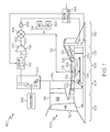
- FIG. 1 is a simplified schematic representation of an exemplary turbofan gas turbine engine that includes a turbine drive system including a lock-up clutch according to an embodiment.
- FIG. 1 A simplified representation of an exemplary multi-spool turbofan gas turbine jet engine 100 is depicted in FIG. 1 , and includes an intake section 102, a compressor section 104, a combustion section 106, a turbine section 108, and an exhaust section 110.
- the intake section 102 includes a fan 112, which is mounted in a fan case 114.
- the fan 112 draws air into the intake section 102 and accelerates it.
- a fraction of the accelerated air exhausted from the fan 112 is directed through a bypass section 116 (shown only partially in FIG. 1 ) disposed between the fan case 114 and an engine case 118, and provides a forward thrust.
- the remaining fraction of air exhausted from the fan 112 is directed into the compressor section 104.
- the compressor section 104 includes two compressors, a low pressure compressor 120, and a high pressure compressor 122.
- the low pressure compressor 120 raises the pressure of the air directed into it from the fan 112, and directs the compressed air into the high pressure compressor 122.
- the high pressure compressor 122 compresses the air still further, and directs the high pressure air into the combustion section 106.
- the combustion section 106 which includes a combustor 124, a plurality of non-illustrated fuel injectors, and one or more non-illustrated igniters, the high pressure air is mixed with fuel and combusted. The combusted air is then directed into the turbine section 108.
- the turbine section 108 includes two turbines, a high pressure turbine 126 and a low pressure turbine 128, disposed in axial flow series in the engine case 118.
- the combusted air from the combustion section 106 expands through each turbine 126 and 128, causing each to rotate.
- the air is then exhausted through a propulsion nozzle disposed in the exhaust section 110, providing addition forward thrust.
- each drives equipment in the engine 100 via concentrically disposed shafts or spools.
- the low pressure turbine 128 drives the fan 112 and the low pressure compressor 120 via a low pressure spool 136
- the high pressure turbine 126 drives the high pressure compressor 122 via a high pressure spool 134.
- the high pressure compressor 122 is configured to drive engine accessory gearbox mounted accessories 138, such as a generator, pumps, or the like. More specifically, in addition to the above-described components, the engine 100 also includes a gearbox 140. In the depicted embodiment, the high pressure spool 134 is coupled to the engine accessory gearbox 140 via a bevel gear driven tower shaft 142. The engine accessory gearbox 140 is in turn coupled to the drive engine accessory gearbox mounted accessories 138. Thus, whenever the high pressure turbine 126 rotates, it supplies a drive force, via the engine accessory gearbox 140, to the drive engine accessory gearbox mounted accessories 138. For example, electric power is generated and supplied, for example, to the aircraft electrical distribution system for use by various other systems and components. In one specific embodiment, it will be appreciated that the drive engine accessory gearbox mounted accessories 138 may be any one of numerous types of AC or DC generators, but in a preferred embodiment it is a brushless AC generator.
- the overall operation of the engine 100 is controlled via an engine controller 144.
- the engine controller 144 as is generally known, is used to control the output power of the engine 100 by, for example, controlling fuel flow rate to the engine 100, as well as controlling airflow through the engine 100.
- the engine controller 144 receives signals from a plurality of sensors 146 that are disposed at various locations on and within the engine 100.
- the sensors 146 are used to sense various physical parameters associated with the engine 100 such as, for example, various temperatures, engine speed, and air flow, and supply signals representative of the sensed parameters to the engine controller 144.
- the engine controller 144 processes the signals received from the sensors 146 and, among other things, supplies various commands to the engine 100 to control its operation.
- the engine controller 144 may be any one of numerous types of engine controllers such as, for example, a FADEC (Full Authority Digital Engine Controller). As will be described more fully further below, the engine controller 144 also controls the flow of bleed air from the engine 100. Before doing so, however, a detailed description of the remaining components depicted in FIG. 1 will be provided.
- FADEC Full Authority Digital Engine Controller
- a pneumatically driven turbine drive system 150 is coupled to the engine 100, and is used to selectively bleed some of the air discharged from the high pressure compressor 122. As may be readily seen, the bleed air supplied to the pneumatically driven turbine drive system 150 bypasses the high pressure turbine 126 and the low pressure turbine 128, thereby reducing the thrust generated by the engine 100.
- the pneumatically driven turbine drive system 150 includes a bleed air conduit 152, a flow control valve 154, and an air turbine 156.
- the bleed air conduit 152 includes an inlet port 158, an outlet port 160, and a flow passage 162 fluidly coupling the inlet 158 and outlet 160 ports together.
- the inlet port 158 is fluidly coupled to the high pressure compressor 122
- the outlet port 160 is fluidly coupled to the air turbine 156.
- the bleed air conduit 152 is optionally fluidly coupled to additional bleed air sources, namely an auxiliary power unit (APU) 164 and/or a ground power unit (GPU) 166.
- APU auxiliary power unit
- GPU ground power unit
- the use of bleed air from the high pressure compressor 122 allows for use of the existing aircraft bleed air system, including these optional bleed air sources (APU 164 and GPU 166) and eliminates any need for a heat exchanger upstream of the air turbine 156 due to the low temperature of the bleed air extracted from the high pressure compressor 122.
- lighter weight materials such as aluminum and titanium, may be used to form the components of the turbine drive system 150 due to the low temperature of the extracted bleed air.
- the flow control valve 154 is mounted on the bleed air conduit 152 and is movable between a closed position and an open position. In the closed position, the bleed air conduit inlet port 158 is fluidly isolated from the bleed air conduit outlet port 160, and bleed air flow through the bleed air conduit flow passage 162 is prevented. Conversely, when the flow control valve 154 is in the open position, the bleed air conduit inlet 158 and outlet 160 ports are in fluid communication with one another, and bleed air flows through the bleed air conduit flow passage 162 to the air turbine 156. The position of the flow control valve 154 is controlled via valve position commands supplied by the engine controller 144.
- the flow control valve 154 includes a valve actuator 168 that is configured to receive the valve position commands and, in response to the commands, move the flow control valve 154 to the commanded position.
- the commanded position may be the closed position, the fully open position, or some throttle position between the closed and fully open position.
- the air turbine 156 includes a fluid inlet 170 and a rotationally mounted air turbine output shaft 172.
- the air turbine fluid inlet 170 is, as alluded to above, coupled to the bleed air conduit outlet port 160.
- the air turbine 156 is additionally coupled, via the air turbine output shaft 172, to the engine accessory gearbox 140.
- bleed air flows through the bleed air conduit 152, and into and through the air turbine 156, causing it to rotate.
- the air turbine 156 rotates, it supplies a drive force to the engine accessory gearbox 140, via the air turbine output shaft 172.
- the drive force supplied by the air turbine 156 supplements the drive force supplied to the engine accessory gearbox 140 from the high pressure compressor 122 for driving the drive engine accessory gearbox mounted accessories 138.
- the air turbine 156 may be any one of numerous types of air turbines including, for example, a vaned radial turbine, a vaneless radial turbine, and a vaned axial turbine.
- the drive force supplied by the air turbine 156 provides power back to the engine core via a bevel gear driven tower shaft 142.
- the pneumatically driven turbine drive system 150 also includes a lock-up clutch 180.
- the lock-up clutch 180 is coupled between the air turbine output shaft 172 and the engine accessory gearbox 140, and is configured to selectively couple the air turbine output shaft 172 to, and decouple the air turbine output shaft 172 from the engine accessory gearbox 140.
- the lock-up clutch 180 is configured to mechanically lock in either rotational direction.
- the lock-up clutch 180 is coupled to receive clutch command signals from the engine controller 144.
- the lock-up clutch 180 In response to the clutch command signals, the lock-up clutch 180 is configured to move to either an engage or disengage position. In the engage position, the lock-up clutch 180 couples the air turbine output shaft 172 to the engine accessory gearbox 140, and in the disengage position the lock-up clutch 180 decouples the air turbine output shaft 172 from the engine accessory gearbox 140. In the locked condition, the lock-up clutch 180 allows the pneumatically driven turbine drive system 150 to respond to changes in engine speed, such as during accelerations and decelerations. In the unlocked condition, the lock-up clutch 180 allows the pneumatically driven turbine drive system 150 to be at rest when it is not required, thereby improving bearing, gear, and seal life.
- the lock-up clutch 180 allows the pneumatically driven turbine drive system 150, and in particular the turbine 156 to remain cool without the need for purge air flow.
- the clutch command signals are preferably supplied by the engine controller 144, it will be appreciated that the commands could be supplied from a dedicated clutch controller or from a separate controller in a different system.
- the engine 100 includes various sensors 146 that sense various physical parameters associated with the engine 100, and supply sensor signals representative of the sensed parameters to the engine controller 144.
- the engine controller 144 additionally receives input signals representative of, for example, the thrust being commanded of the engine 100 from the cockpit.
- the engine controller 144 based at least in part on the sensor signals, determines the operational state of the engine 100 and supplies, among other things, appropriate command signals to the flow control valve 154 and the lock-up clutch 180, to thereby move these components to the appropriate positions.
- the engine controller 144 determines that the air flow through the low pressure compressor 122 exceeds that which is needed for the commanded thrust, the engine controller 144 will issue appropriate valve position command signals and clutch command signals to move the flow control valve 154 to a desired position, and the lock-up clutch 180 to the engage position. As a result, a portion of the air discharged from the high pressure compressor 122 will be bled away from the high pressure turbine 126 and the low pressure turbine 128, and into the bleed air conduit 152. It will be appreciated that the flow rate through the bleed air conduit 152 is based, at least in part, on the commanded position of the flow control valve 154.
- the flow of bleed air is directed into the air turbine 156, causing it to rotate and supply a drive force to the engine accessory gearbox 140, to thereby assist the high pressure compressor 122 in driving the drive engine accessory gearbox mounted accessories 138 and provide power back into the engine core thereby moving the engine operating line away from the compressor surge.
- This will reduce the amount of air the turbine engine 100 will be bleeding overboard during aircraft descent (and other lower engine thrust conditions) where there is a high electrical power demand on the engine 100.
- the engine controller 144 determines that the pneumatically driven turbine drive system 150 is not needed, the engine controller 144 will issue appropriate command signals that move the flow control valve 154 to the closed positions, and the lock-up clutch 180 to the disengaged position. As a result, no air is bled from the engine 100 and the drive force supplied to the drive engine accessory gearbox mounted accessories 138 comes solely from the bevel gear driven tower shaft 142.
- the pneumatically driven turbine drive system 150 selectively supplements the power supplied to the engine accessory gearbox 140 and thus reduces the power extracted from the high pressure compressor 122. This, coupled with the bleed air that is diverted from the high pressure turbine 126 and the low pressure turbine 128, allows the low pressure spool 136 to run at lower speeds when high engine thrust is not needed or desired, but when the drive engine accessory gearbox mounted accessories 138 is still needed to supply high electrical loads. In addition, providing electrical power back into the engine 100 allows the engine core to run slower and cooler, reduces fuel consumption and reduces the engine turbine temperatures resulting in improved engine life
Abstract
Description
- The present invention relates to gas turbine engines and, more particularly, to a gas turbine engine drive system including a lock-up clutch and method for extracting fluid power from the gas turbine engine and converting it to mechanical power in a gearbox.
- A gas turbine engine may be used to supply power to various types of vehicles and systems. For example, gas turbine engines may be used to supply propulsion power to an aircraft. Many gas turbine engines include at least three major sections, a compressor section, a combustor section, and a turbine section. The compressor section receives a flow of intake air and raises the pressure of this air to a relatively high level. In a multi-spool (e.g., multi-shaft) engine, the compressor section may include two or more compressors. The compressed air from the compressor section then enters the combustor section, where a ring of fuel nozzles injects a steady stream of fuel. The injected fuel is ignited by a burner, which significantly increases the energy of the compressed air.
- The high-energy compressed air from the combustor section then flows into and through the turbine section, causing rotationally mounted turbine blades to rotate and generate energy. The air exiting the turbine section is then exhausted from the engine. Similar to the compressor section, in a multi-spool engine the turbine section may include a plurality of turbines. The energy generated in each of the turbines may be used to power other portions of the engine.
- In addition to providing propulsion power, a gas turbine engine may also be used to supply either, or both, electrical and pneumatic power to the aircraft. For example, in the past some gas turbine engines include a bleed air port between the compressor section and the turbine section. The bleed air port allows some of the compressed air from the compressor section to be diverted away from the turbine section, and used for other functions such as, for example, main engine starting air, environmental control, and/or cabin pressure control. More recently, however, gas turbine engines are being designed to not include bleed air ports. This is in response to a desire to more fully utilize electrical power for main engine starting air, environmental control, and cabin pressure control. Thus, instead of using bleed air to support these various functions, the high pressure turbine may be used to drive one or more electrical generators to supply electrical power to support these functions.
- Accordingly, the next generation of aircraft may be more electric in architecture. This reliance on electric power may increase the generator load and therefore shaft horsepower (SHP) extraction load on the high pressure (HP) spool of the propulsion engine (SHP load/thrust ratio is increasing). As a result, the engine may not be able to keep up with the generator load demand at various low thrust conditions in the flight envelope. As a result, the engine may be required to run at high core speeds and surge bleed to reduce engine thrust.
- In a typical turbine engine, the turbine drive system (TDS) may extract pneumatic power from the aircraft bleed air system, including surge bleed, convert it into mechanical power and supply the power back into the engine accessory gearbox via a rotating shaft. This process in effect may off-set a portion of the electrical load. The generation of this mechanical power may provide gearbox power assistance during periods of engine operation throughout the engine operating speed range. During aircraft operation, peak power from the TDS may typically be demanded at speeds ranging from idle to maximum power (roughly between 60-100% engine speed). This power assistance may offset engine core power required to drive a number of engine accessory gearbox mounted accessories (generators, pumps, etc.). The TDS may be powered by a controlled supply of pneumatic energy from the engine itself (high, low, or intermediate stage, etc.) or from an external source such as an auxiliary power unit (APU), ground power unit (GPU), or another engine, via the aircraft's pneumatic distribution system.
- The TDS requires both mechanical fixation when in the energized mode (TDS control valve open) and mechanically disengagement when deenergized. More specifically, when energized, the TDS must be capable of responding to fast changes in engine speed (engine accelerations/decelerations, i.e. Bode's) which is best served by a mechanically fixed turbine drive. When not energized, the TDS must be capable of mechanically disengagement to allow the drive turbine to come to rest. This mechanical disengagement may result in the prevention of turbine overheating, and wear with respect to bearings, gears and seals in the TDS, and improve engine performance.
- Hence, there is a need for a TDS that is capable of responding to engine accelerations and decelerations when required via mechanical engagement to the engine core and disengagement when not in use. The system should not significantly reduce engine efficiency, and/or significantly increase fuel consumption, and/or increase overall operational costs. The present invention addresses one or more of these needs.
- The present invention provides a gas turbine engine including a turbine drive system and method.
- In one embodiment, and by way of example only, a gas turbine engine including a turbine drive system comprises an engine case; a low pressure compressor, a high pressure compressor, a high pressure turbine and a low pressure turbine disposed in flow series within the engine case. The high pressure compressor and the high pressure turbine are mounted on a high pressure spool and the low pressure compressor and the low pressure turbine are mounted on a low pressure spool. Each spool is rotationally mounted within the engine case. At least one engine accessory has an input shaft coupled to the high pressure spool to receive a drive force therefrom. The drive system further includes a bleed air conduit having an inlet port, an outlet port, and a flow passage therebetween. The bleed air conduit inlet port is fluidly coupled to the high pressure compressor to receive a flow of bleed air from the high pressure compressor. A flow control valve is mounted on the bleed air conduit and selectively movable between at least a closed position, in which the bleed air conduit inlet port is fluidly isolated from the bleed air conduit outlet port, and an open position, in which the bleed air conduit inlet port is in fluid communication with the bleed air conduit outlet port. The system further comprises an air turbine having a fluid inlet and a rotationally mounted air turbine output shaft. The air turbine fluid inlet is in fluid communication with the bleed air conduit outlet port to receive bleed air therefrom when the flow control valve is in the open position. The air turbine output shaft is coupled to the at least one engine accessory. The system further includes a lock-up clutch coupled between the air turbine output shaft and the at least one engine accessory and movable between (i) an engage position, in which the air turbine output shaft is coupled to the at least one engine accessory in a first rotational direction and a second rotational direction opposite the first rotational direction, and (ii) a disengage position, in which the air turbine output shaft is not coupled to the at least one engine accessory.
- In another particular embodiment, and by way of example only, there is provided a gas turbine engine including a turbine drive system, comprising: an engine case; a low pressure compressor, a high pressure compressor, a high pressure turbine and a low pressure turbine disposed in flow series within the engine case, an engine accessory gearbox, at least one engine accessory, a bleed air conduit, a flow control valve mounted on the bleed air conduit, an air turbine, and a lock-up clutch. The high pressure turbine and the high pressure compressor are mounted on a high pressure spool, and the low pressure compressor and the low pressure turbine are mounted on a low pressure spool, each spool rotationally mounted within the engine case. The engine accessory gearbox includes an input shaft coupled to the high pressure spool to receive a drive force therefrom and operable, upon receipt of the drive force. The at least one engine accessory includes an input shaft coupled to the engine accessory gearbox to receive the drive force therefrom and operable, upon receipt of the drive force. The bleed air conduit includes an inlet port, an outlet port, and a flow passage therebetween. The bleed air conduit inlet port is fluidly coupled to the high pressure compressor to receive a flow of bleed air from the high pressure compressor. The flow control valve is selectively movable between at least a closed position, in which the bleed air conduit inlet port is fluidly isolated from the bleed air conduit outlet port, and an open position, in which the bleed air conduit inlet port is in fluid communication with the bleed air conduit outlet port. The air turbine includes a fluid inlet and a rotationally mounted output shaft. The air turbine fluid inlet is in fluid communication with the bleed air conduit outlet port to receive bleed air therefrom when the flow control valve is in the open position. The air turbine output shaft is coupled to the at least one engine accessory. The lock-up clutch is coupled between the air turbine output shaft and the engine accessory gearbox and movable between (i) an engage position, in which the air turbine output shaft is coupled to the engine accessory gearbox, and (ii) a disengage position, in which the air turbine output shaft is not coupled to the engine accessory gearbox.
- In yet another particular embodiment, and by way of example only, there is provided a gas turbine engine system including a low pressure compressor, a high pressure compressor, a high pressure turbine, a low pressure turbine, and at least one engine accessory coupled to the high pressure compressor to receive a drive force therefrom, a method of providing a pneumatically driven turbine drive system to the high pressure compressor, comprising the steps of: determining an operational state of the gas turbine engine system; and selectively supplying air discharged from the high pressure compressor to an air turbine that is coupled to the at least one engine accessory based at least in part on the determined operational state, whereby the air turbine rotates and supplies the drive force to the at least one engine accessory in addition to that provided by the high pressure compressor.
- Other independent features and advantages of the preferred turbine drive system and method will become apparent from the following detailed description, taken in conjunction with the accompanying drawings which illustrate, by way of example, the principles of the invention.
-
FIG. 1 is a simplified schematic representation of an exemplary turbofan gas turbine engine that includes a turbine drive system including a lock-up clutch according to an embodiment. - Before proceeding with the detailed description, it is to be appreciated that the following detailed description is merely exemplary in nature and is not intended to limit the invention or the application and uses of the invention. In this regard, it is to be additionally appreciated that the described embodiment is not limited to use in conjunction with a particular type of turbine engine. Hence, although the present embodiment is, for convenience of explanation, depicted and described as being implemented in a multi-spool gas turbine jet engine, it will be appreciated that it can be implemented in various other types of turbines, and in various other systems and environments. Furthermore, there is no intention to be bound by any theory presented in the preceding background or the following detailed description.
- A simplified representation of an exemplary multi-spool turbofan gas
turbine jet engine 100 is depicted inFIG. 1 , and includes anintake section 102, acompressor section 104, acombustion section 106, aturbine section 108, and anexhaust section 110. Theintake section 102 includes afan 112, which is mounted in afan case 114. Thefan 112 draws air into theintake section 102 and accelerates it. A fraction of the accelerated air exhausted from thefan 112 is directed through a bypass section 116 (shown only partially inFIG. 1 ) disposed between thefan case 114 and anengine case 118, and provides a forward thrust. The remaining fraction of air exhausted from thefan 112 is directed into thecompressor section 104. - The
compressor section 104 includes two compressors, alow pressure compressor 120, and ahigh pressure compressor 122. Thelow pressure compressor 120 raises the pressure of the air directed into it from thefan 112, and directs the compressed air into thehigh pressure compressor 122. Thehigh pressure compressor 122 compresses the air still further, and directs the high pressure air into thecombustion section 106. In thecombustion section 106, which includes acombustor 124, a plurality of non-illustrated fuel injectors, and one or more non-illustrated igniters, the high pressure air is mixed with fuel and combusted. The combusted air is then directed into theturbine section 108. - The
turbine section 108 includes two turbines, ahigh pressure turbine 126 and alow pressure turbine 128, disposed in axial flow series in theengine case 118. The combusted air from thecombustion section 106 expands through eachturbine exhaust section 110, providing addition forward thrust. As theturbines engine 100 via concentrically disposed shafts or spools. For example, thelow pressure turbine 128 drives thefan 112 and thelow pressure compressor 120 via alow pressure spool 136, and thehigh pressure turbine 126 drives thehigh pressure compressor 122 via ahigh pressure spool 134. - The
high pressure compressor 122 is configured to drive engine accessory gearbox mountedaccessories 138, such as a generator, pumps, or the like. More specifically, in addition to the above-described components, theengine 100 also includes a gearbox 140. In the depicted embodiment, thehigh pressure spool 134 is coupled to the engine accessory gearbox 140 via a bevel gear driventower shaft 142. The engine accessory gearbox 140 is in turn coupled to the drive engine accessory gearbox mountedaccessories 138. Thus, whenever thehigh pressure turbine 126 rotates, it supplies a drive force, via the engine accessory gearbox 140, to the drive engine accessory gearbox mountedaccessories 138. For example, electric power is generated and supplied, for example, to the aircraft electrical distribution system for use by various other systems and components. In one specific embodiment, it will be appreciated that the drive engine accessory gearbox mountedaccessories 138 may be any one of numerous types of AC or DC generators, but in a preferred embodiment it is a brushless AC generator. - The overall operation of the
engine 100 is controlled via anengine controller 144. Theengine controller 144, as is generally known, is used to control the output power of theengine 100 by, for example, controlling fuel flow rate to theengine 100, as well as controlling airflow through theengine 100. In the depicted embodiment, theengine controller 144 receives signals from a plurality ofsensors 146 that are disposed at various locations on and within theengine 100. Thesensors 146 are used to sense various physical parameters associated with theengine 100 such as, for example, various temperatures, engine speed, and air flow, and supply signals representative of the sensed parameters to theengine controller 144. Theengine controller 144 processes the signals received from thesensors 146 and, among other things, supplies various commands to theengine 100 to control its operation. It will be appreciated that theengine controller 144 may be any one of numerous types of engine controllers such as, for example, a FADEC (Full Authority Digital Engine Controller). As will be described more fully further below, theengine controller 144 also controls the flow of bleed air from theengine 100. Before doing so, however, a detailed description of the remaining components depicted inFIG. 1 will be provided. - As was previously mentioned, during relatively low engine thrust operations the
high pressure compressor 122 still needs to supply sufficient drive force to the drive engine accessory gearbox mountedaccessories 138 to maintain the needed electrical load. Thus, air flow through thehigh pressure compressor 122 may be higher than what is needed to supply the desired engine thrust. As shown inFIG. 1 , a pneumatically driventurbine drive system 150 is coupled to theengine 100, and is used to selectively bleed some of the air discharged from thehigh pressure compressor 122. As may be readily seen, the bleed air supplied to the pneumatically driventurbine drive system 150 bypasses thehigh pressure turbine 126 and thelow pressure turbine 128, thereby reducing the thrust generated by theengine 100. - The pneumatically driven
turbine drive system 150 includes ableed air conduit 152, aflow control valve 154, and anair turbine 156. Thebleed air conduit 152 includes aninlet port 158, anoutlet port 160, and aflow passage 162 fluidly coupling theinlet 158 andoutlet 160 ports together. Theinlet port 158 is fluidly coupled to thehigh pressure compressor 122, and theoutlet port 160 is fluidly coupled to theair turbine 156. Thus, when bleed air flows through thebleed air conduit 152, the bleed air is supplied to theair turbine 156, causing it to rotate. Thebleed air conduit 152 is optionally fluidly coupled to additional bleed air sources, namely an auxiliary power unit (APU) 164 and/or a ground power unit (GPU) 166. The use of bleed air from thehigh pressure compressor 122 allows for use of the existing aircraft bleed air system, including these optional bleed air sources (APU 164 and GPU 166) and eliminates any need for a heat exchanger upstream of theair turbine 156 due to the low temperature of the bleed air extracted from thehigh pressure compressor 122. In addition, by extracting bleed air surge or discharge from thehigh pressure compressor 122 in contrast to extracting bleed air from the high andlow pressure turbines turbine drive system 150 due to the low temperature of the extracted bleed air. - The
flow control valve 154 is mounted on thebleed air conduit 152 and is movable between a closed position and an open position. In the closed position, the bleed airconduit inlet port 158 is fluidly isolated from the bleed airconduit outlet port 160, and bleed air flow through the bleed airconduit flow passage 162 is prevented. Conversely, when theflow control valve 154 is in the open position, the bleedair conduit inlet 158 andoutlet 160 ports are in fluid communication with one another, and bleed air flows through the bleed airconduit flow passage 162 to theair turbine 156. The position of theflow control valve 154 is controlled via valve position commands supplied by theengine controller 144. As such, theflow control valve 154 includes avalve actuator 168 that is configured to receive the valve position commands and, in response to the commands, move theflow control valve 154 to the commanded position. It will be appreciated that the commanded position may be the closed position, the fully open position, or some throttle position between the closed and fully open position. - The
air turbine 156 includes afluid inlet 170 and a rotationally mounted airturbine output shaft 172. The airturbine fluid inlet 170 is, as alluded to above, coupled to the bleed airconduit outlet port 160. Theair turbine 156 is additionally coupled, via the airturbine output shaft 172, to the engine accessory gearbox 140. Thus, when theflow control valve 154 is moved to an open position, bleed air flows through thebleed air conduit 152, and into and through theair turbine 156, causing it to rotate. As theair turbine 156 rotates, it supplies a drive force to the engine accessory gearbox 140, via the airturbine output shaft 172. The drive force supplied by theair turbine 156 supplements the drive force supplied to the engine accessory gearbox 140 from thehigh pressure compressor 122 for driving the drive engine accessory gearbox mountedaccessories 138. It will be appreciated that theair turbine 156 may be any one of numerous types of air turbines including, for example, a vaned radial turbine, a vaneless radial turbine, and a vaned axial turbine. In addition, the drive force supplied by theair turbine 156 provides power back to the engine core via a bevel gear driventower shaft 142. - When the
engine 100 is operating and theflow control valve 154 is in the closed position, thehigh pressure compressor 122 could back drive theair turbine 156. This could be potentially detrimental to theair turbine 156 and could additionally result in unwanted energy dissipation. Thus, asFIG. 1 additionally shows, the pneumatically driventurbine drive system 150 also includes a lock-upclutch 180. The lock-upclutch 180 is coupled between the airturbine output shaft 172 and the engine accessory gearbox 140, and is configured to selectively couple the airturbine output shaft 172 to, and decouple the airturbine output shaft 172 from the engine accessory gearbox 140. In the depicted embodiment, the lock-upclutch 180 is configured to mechanically lock in either rotational direction. The lock-upclutch 180 is coupled to receive clutch command signals from theengine controller 144. In response to the clutch command signals, the lock-upclutch 180 is configured to move to either an engage or disengage position. In the engage position, the lock-up clutch 180 couples the airturbine output shaft 172 to the engine accessory gearbox 140, and in the disengage position the lock-upclutch 180 decouples the airturbine output shaft 172 from the engine accessory gearbox 140. In the locked condition, the lock-upclutch 180 allows the pneumatically driventurbine drive system 150 to respond to changes in engine speed, such as during accelerations and decelerations. In the unlocked condition, the lock-upclutch 180 allows the pneumatically driventurbine drive system 150 to be at rest when it is not required, thereby improving bearing, gear, and seal life. In addition, when in the unlocked condition, the lock-upclutch 180 allows the pneumatically driventurbine drive system 150, and in particular theturbine 156 to remain cool without the need for purge air flow. Although the clutch command signals are preferably supplied by theengine controller 144, it will be appreciated that the commands could be supplied from a dedicated clutch controller or from a separate controller in a different system. - Having described the configurations of the
engine 100 and the pneumatically driventurbine drive system 150, and the general functionality of each, a more detailed description of the overall operation and interaction of the engine and pneumatically driventurbine drive system 150 will now be provided. As noted above, theengine 100 includesvarious sensors 146 that sense various physical parameters associated with theengine 100, and supply sensor signals representative of the sensed parameters to theengine controller 144. Theengine controller 144 additionally receives input signals representative of, for example, the thrust being commanded of theengine 100 from the cockpit. Theengine controller 144, based at least in part on the sensor signals, determines the operational state of theengine 100 and supplies, among other things, appropriate command signals to theflow control valve 154 and the lock-upclutch 180, to thereby move these components to the appropriate positions. - For example, if the
engine controller 144 determines that the air flow through thelow pressure compressor 122 exceeds that which is needed for the commanded thrust, theengine controller 144 will issue appropriate valve position command signals and clutch command signals to move theflow control valve 154 to a desired position, and the lock-upclutch 180 to the engage position. As a result, a portion of the air discharged from thehigh pressure compressor 122 will be bled away from thehigh pressure turbine 126 and thelow pressure turbine 128, and into thebleed air conduit 152. It will be appreciated that the flow rate through thebleed air conduit 152 is based, at least in part, on the commanded position of theflow control valve 154. In any case, the flow of bleed air is directed into theair turbine 156, causing it to rotate and supply a drive force to the engine accessory gearbox 140, to thereby assist thehigh pressure compressor 122 in driving the drive engine accessory gearbox mountedaccessories 138 and provide power back into the engine core thereby moving the engine operating line away from the compressor surge. This will reduce the amount of air theturbine engine 100 will be bleeding overboard during aircraft descent (and other lower engine thrust conditions) where there is a high electrical power demand on theengine 100. - Conversely, if the
engine controller 144 determines that the pneumatically driventurbine drive system 150 is not needed, theengine controller 144 will issue appropriate command signals that move theflow control valve 154 to the closed positions, and the lock-upclutch 180 to the disengaged position. As a result, no air is bled from theengine 100 and the drive force supplied to the drive engine accessory gearbox mountedaccessories 138 comes solely from the bevel gear driventower shaft 142. - The pneumatically driven
turbine drive system 150 selectively supplements the power supplied to the engine accessory gearbox 140 and thus reduces the power extracted from thehigh pressure compressor 122. This, coupled with the bleed air that is diverted from thehigh pressure turbine 126 and thelow pressure turbine 128, allows thelow pressure spool 136 to run at lower speeds when high engine thrust is not needed or desired, but when the drive engine accessory gearbox mountedaccessories 138 is still needed to supply high electrical loads. In addition, providing electrical power back into theengine 100 allows the engine core to run slower and cooler, reduces fuel consumption and reduces the engine turbine temperatures resulting in improved engine life - While the invention has been described with reference to a preferred embodiment, it will be understood by those skilled in the art that various changes may be made and equivalents may be substituted for elements thereof without departing from the scope of the invention. In addition, many modifications may be made to adapt to a particular situation or material to the teachings of the invention without departing from the essential scope thereof. Therefore, it is intended that the invention not be limited to the particular embodiment disclosed as the best mode contemplated for carrying out this invention, but that the invention will include all embodiments falling within the scope of the appended claims.
Claims (10)
- A gas turbine engine (100) including a turbine drive system (150), comprising:an engine case (118);a low pressure compressor (120), a high pressure compressor (122), a high pressure turbine (126) and a low pressure turbine (128) disposed in flow series within the engine case (118), the high pressure compressor (122) and the high pressure turbine (126) mounted on a high pressure spool (134) and the low pressure compressor (120) and the low pressure turbine (128) mounted on a low pressure spool (136), each spool rotationally mounted within the engine case (118);at least one engine accessory gearbox mounted accessory (138) having an input shaft (142) coupled to the high pressure spool (134) to receive a drive force therefrom;a bleed air conduit (152) having an inlet port (158), an outlet port (160), and a flow passage (162) therebetween, the bleed air conduit inlet port (158) fluidly coupled to the high pressure compressor (122) to receive a flow of bleed air from the high pressure compressor (122);a flow control valve (154) mounted on the bleed air conduit (152) and selectively movable between at least a closed position, in which the bleed air conduit inlet port (158) is fluidly isolated from the bleed air conduit outlet port (160), and an open position, in which the bleed air conduit inlet port (158) is in fluid communication with the bleed air conduit outlet port (160);an air turbine (156) having a fluid inlet (170) and a rotationally mounted air turbine output shaft (172), the air turbine fluid inlet (170) in fluid communication with the bleed air conduit outlet port (160) to receive bleed air therefrom when the flow control valve (154) is in the open position, the air turbine output shaft (172) coupled to the at least one engine accessory gearbox mounted accessory (138); anda lock-up clutch (180) coupled between the air turbine output shaft (172) and the at least one engine accessory gearbox mounted accessory (138) and movable between (i) an engage position, in which the air turbine output shaft (172) is coupled to the at least one engine accessory gearbox mounted accessory (138) in a first rotational direction and a second rotational direction opposite the first rotational direction, and (ii) a disengage position, in which the air turbine output shaft (172) is not coupled to the at least one engine accessory gearbox mounted accessory (138).
- They system of Claim 1, wherein the at least one engine accessory gearbox mounted accessory (138) is one of a generator and an engine pump.
- The system of Claim 2, further comprising:one or more gears coupled between the high pressure spool (134) and the at least one engine accessory gearbox mounted accessory (138).
- The system of Claim 3, further comprising:one or more gears coupled between the air turbine output shaft (172) and the at least one engine accessory gearbox mounted accessory (138).
- The system of Claim 2, further comprising:one or more gears coupled between the air turbine output shaft (172) and a core of the gas turbine engine (100).
- The system of Claim 5, further comprising:a fan case (114) at least partially surrounding the engine case (118) and spaced apart therefrom to form an air bypass section (116);a fan (112) coupled to the low pressure spool (136) and configured, upon rotation thereof, to supply a flow of fan bypass air through the air bypass flow passage (162).
- The system of Claim 2, wherein the at least one engine accessory gearbox mounted accessory (138) is a generator configured, upon receipt of the drive force, to generate electrical power.
- The system of Claim 7, wherein the generator is coupled to a core of the gas turbine engine (100) to provide the electrical power thereto.
- The system of Claim 2, further comprising:a controller (144) adapted to receive one or more sensor signals representative of one or more engine parameters and operable, in response thereto, to supply one or more valve position command signals; anda valve actuator (168) coupled to the flow control valve (154), the valve actuator (168) coupled to receive the one or more valve position command signals and operable, in response thereto, to selectively move the flow control valve (154) to a commanded position, to thereby control the flow of bleed air to the air turbine (156).
- A gas turbine engine (100) including a turbine drive system (150), comprising:an engine case (118);a low pressure compressor (120), a high pressure compressor (122), a high pressure turbine (126) and a low pressure turbine (128) disposed in flow series within the engine case (118), the high pressure turbine (126) and the high pressure compressor (122) mounted on a high pressure spool (134), and the low pressure compressor (120) and the low pressure turbine (128) mounted on a low pressure spool (136), each spool rotationally mounted within the engine case (118);an engine accessory gearbox (140) having an input shaft (142) coupled to the high pressure spool (134) to receive a drive force therefrom and operable, upon receipt of the drive force;at least one engine accessory gearbox mounted accessory (138) having an input shaft coupled to the engine accessory gearbox (140) to receive the drive force therefrom and operable, upon receipt of the drive force;a bleed air conduit (152) having an inlet port (158), an outlet port (160), and a flow passage (162) therebetween, the bleed air conduit inlet port (158) fluidly coupled to the high pressure compressor (122) to receive a flow of bleed air from the high pressure compressor (122);a flow control valve (154) mounted on the bleed air conduit (152) and selectively movable between at least a closed position, in which the bleed air conduit inlet port (158) is fluidly isolated from the bleed air conduit outlet port (160), and an open position, in which the bleed air conduit inlet port (158) is in fluid communication with the bleed air conduit outlet port (160);an air turbine (156) having a fluid inlet (170) and a rotationally mounted output shaft (172), the air turbine fluid inlet (170) in fluid communication with the bleed air conduit outlet port (160) to receive bleed air therefrom when the flow control valve (154) is in the open position, the air turbine output shaft (172) coupled to the at least one engine accessory gearbox mounted accessory (138); anda lock-up clutch (180) coupled between the air turbine output shaft (172) and the engine accessory gearbox (140) and movable between (i) an engage position, in which the air turbine output shaft (172) is coupled to the engine accessory gearbox (140), and (ii) a disengage position, in which the air turbine output shaft (172) is not coupled to the engine accessory gearbox (140).
Applications Claiming Priority (1)
| Application Number | Priority Date | Filing Date | Title |
|---|---|---|---|
| US12/124,362 US8146370B2 (en) | 2008-05-21 | 2008-05-21 | Turbine drive system with lock-up clutch and method |
Publications (3)
| Publication Number | Publication Date |
|---|---|
| EP2128404A2 true EP2128404A2 (en) | 2009-12-02 |
| EP2128404A3 EP2128404A3 (en) | 2014-03-12 |
| EP2128404B1 EP2128404B1 (en) | 2016-11-30 |
Family
ID=40688350
Family Applications (1)
| Application Number | Title | Priority Date | Filing Date |
|---|---|---|---|
| EP09159954.8A Not-in-force EP2128404B1 (en) | 2008-05-21 | 2009-05-11 | Gas turbine drive system for auxiliaries with lock-up clutch |
Country Status (2)
| Country | Link |
|---|---|
| US (1) | US8146370B2 (en) |
| EP (1) | EP2128404B1 (en) |
Cited By (4)
| Publication number | Priority date | Publication date | Assignee | Title |
|---|---|---|---|---|
| WO2014046842A1 (en) * | 2012-09-19 | 2014-03-27 | United Technologies Corporation | System for decoupling drive shaft of variable area fan nozzle |
| EP2452879A3 (en) * | 2010-11-16 | 2014-12-24 | Rolls-Royce Corporation | Aircraft and propulsion system |
| EP3330515A1 (en) * | 2016-12-05 | 2018-06-06 | United Technologies Corporation | Cooling air for gas turbine engine with supercharged low pressure compressor |
| EP3783212A1 (en) * | 2019-08-23 | 2021-02-24 | Raytheon Technologies Corporation | Gas turbine engine and method for operating same |
Families Citing this family (55)
| Publication number | Priority date | Publication date | Assignee | Title |
|---|---|---|---|---|
| US8887485B2 (en) * | 2008-10-20 | 2014-11-18 | Rolls-Royce North American Technologies, Inc. | Three spool gas turbine engine having a clutch and compressor bypass |
| JP5016706B2 (en) * | 2009-11-04 | 2012-09-05 | 川崎重工業株式会社 | Aircraft starter generator |
| US9175605B2 (en) * | 2009-12-29 | 2015-11-03 | Rolls-Royce Corporation | Gas turbine engine surge margin bleed power recuperation |
| US20110277467A1 (en) * | 2010-05-12 | 2011-11-17 | Martin Dravis | Hybrid air turbine engine with heat recapture system for moving vehicle |
| US8424416B2 (en) * | 2010-06-18 | 2013-04-23 | Hamilton Sundstrand Corporation | Layshaft generator |
| US8395275B2 (en) * | 2010-11-09 | 2013-03-12 | Hamilton Sundstrand Corporation | Integrated permanent magnet alternator and cooling fan |
| US20120117974A1 (en) * | 2010-11-16 | 2012-05-17 | Hamilton Sundstrand Corporation | Air flow delivery and fuel consumption control for aircraft air management and auxiliary power systems |
| US8955335B2 (en) | 2010-12-30 | 2015-02-17 | Rolls-Royce Corporation | System, propulsion system and vehicle |
| US9261019B2 (en) * | 2010-12-30 | 2016-02-16 | Rolls-Royce North American Technologies, Inc. | Variable cycle gas turbine engine |
| US8991188B2 (en) | 2011-01-05 | 2015-03-31 | General Electric Company | Fuel nozzle passive purge cap flow |
| US8723385B2 (en) | 2011-10-07 | 2014-05-13 | General Electric Company | Generator |
| US8723349B2 (en) | 2011-10-07 | 2014-05-13 | General Electric Company | Apparatus for generating power from a turbine engine |
| US8978351B2 (en) * | 2011-10-21 | 2015-03-17 | United Technologies Corporation | Integrated thermal management system and environmental control system for a gas turbine engine |
| US8966875B2 (en) * | 2011-10-21 | 2015-03-03 | United Technologies Corporation | Constant speed transmission for gas turbine engine |
| US8978352B2 (en) * | 2011-10-21 | 2015-03-17 | United Technologies Corporation | Apparatus and method for operating a gas turbine engine during windmilling |
| US8966876B2 (en) * | 2011-10-21 | 2015-03-03 | United Technologies Corporation | Controllable speed windmill operation of a gas turbine engine through low spool power extraction |
| US9091216B2 (en) | 2011-11-29 | 2015-07-28 | Pratt & Whitney Canada Corp. | Systems and methods for changing a speed of a compressor boost stage in a gas turbine |
| US10125724B2 (en) | 2012-01-17 | 2018-11-13 | United Technologies Corporation | Start system for gas turbine engines |
| US8769962B2 (en) | 2012-01-31 | 2014-07-08 | United Technologies Corporation | Multi-circuit buffer system for a gas turbine engine |
| US10018119B2 (en) * | 2012-04-02 | 2018-07-10 | United Technologies Corporation | Geared architecture with inducer for gas turbine engine |
| US9964214B2 (en) * | 2012-04-02 | 2018-05-08 | United Technologies Corporation | Seal with non-metallic interface |
| JP5568596B2 (en) * | 2012-05-30 | 2014-08-06 | 川崎重工業株式会社 | Aircraft engine gearbox integrated power generator |
| US9045996B2 (en) | 2012-11-20 | 2015-06-02 | Honeywell International Inc. | Gas turbine engine optimization by electric power transfer |
| US9382910B2 (en) | 2013-02-28 | 2016-07-05 | Honeywell International Inc. | Auxiliary power units (APUs) and methods and systems for activation and deactivation of a load compressor therein |
| US20150082805A1 (en) * | 2013-09-23 | 2015-03-26 | Honeywell International Inc. | Air turbine starter including a lightweight, low differential pressure check valve |
| US9771932B2 (en) * | 2014-02-14 | 2017-09-26 | The Boeing Company | Apparatus, controller and method for controlling the cool down of an aircraft engine rotor |
| CN104314693B (en) * | 2014-09-29 | 2016-02-03 | 北京航空航天大学 | A kind of aeroengine multiloop method for handover control based on compensating |
| US10408133B2 (en) * | 2014-10-03 | 2019-09-10 | Pratt & Whitney Canada Corp. | Accessory drive system for a gas turbine engine |
| US10156190B2 (en) * | 2015-05-20 | 2018-12-18 | Honeywell International Inc. | Gas turbine engine uncontrolled high thrust accommodation system and method |
| US10669946B2 (en) | 2015-06-05 | 2020-06-02 | Raytheon Technologies Corporation | Geared architecture for a gas turbine engine |
| US9828870B2 (en) | 2015-06-11 | 2017-11-28 | Northrop Grumman Systems Corporation | Efficient power and thermal management system for high performance aircraft |
| US10578028B2 (en) * | 2015-08-18 | 2020-03-03 | General Electric Company | Compressor bleed auxiliary turbine |
| US10711702B2 (en) | 2015-08-18 | 2020-07-14 | General Electric Company | Mixed flow turbocore |
| EP3246526B1 (en) * | 2016-05-18 | 2021-03-24 | Rolls-Royce Corporation | Control of low pressure shaft generator for gas turbine engine |
| US10883424B2 (en) | 2016-07-19 | 2021-01-05 | Pratt & Whitney Canada Corp. | Multi-spool gas turbine engine architecture |
| US11415063B2 (en) | 2016-09-15 | 2022-08-16 | Pratt & Whitney Canada Corp. | Reverse-flow gas turbine engine |
| US10309303B2 (en) | 2016-08-12 | 2019-06-04 | Hamilton Sundstrand Corporation | Systems and methods of generating electrical power |
| US11022042B2 (en) | 2016-08-29 | 2021-06-01 | Rolls-Royce North American Technologies Inc. | Aircraft having a gas turbine generator with power assist |
| US11035293B2 (en) | 2016-09-15 | 2021-06-15 | Pratt & Whitney Canada Corp. | Reverse flow gas turbine engine with offset RGB |
| US10465611B2 (en) * | 2016-09-15 | 2019-11-05 | Pratt & Whitney Canada Corp. | Reverse flow multi-spool gas turbine engine with aft-end accessory gearbox drivingly connected to both high pressure spool and low pressure spool |
| US10934885B2 (en) | 2016-11-07 | 2021-03-02 | Raytheon Technologies Corporation | System and method for controlling dual starter air valve |
| US10815899B2 (en) | 2016-11-15 | 2020-10-27 | Pratt & Whitney Canada Corp. | Gas turbine engine accessories arrangement |
| US20180216525A1 (en) * | 2017-01-30 | 2018-08-02 | Pratt & Whitney Canada Corp. | Gas turbine engine architecture with split compressor system |
| US10808624B2 (en) | 2017-02-09 | 2020-10-20 | Pratt & Whitney Canada Corp. | Turbine rotor with low over-speed requirements |
| US10746188B2 (en) | 2017-03-14 | 2020-08-18 | Pratt & Whitney Canada Corp. | Inter-shaft bearing connected to a compressor boost system |
| US11255215B2 (en) | 2017-07-06 | 2022-02-22 | Rolls-Royce North American Technologies Inc. | Gas turbine engine with microchannel cooled electric device |
| US11333076B2 (en) | 2017-12-21 | 2022-05-17 | Raytheon Technologies Corporation | Power takeoff transmission |
| GB201808436D0 (en) * | 2018-05-23 | 2018-07-11 | Rolls Royce Plc | Gas turbine engine compressor control method |
| US11920479B2 (en) | 2018-08-08 | 2024-03-05 | Pratt & Whitney Canada Corp. | Multi-engine system and method |
| US11008949B2 (en) * | 2018-09-25 | 2021-05-18 | Pratt & Whitney Canada Corp. | Multi-source air system and switching valve assembly for a gas turbine engine |
| US11041444B2 (en) * | 2018-11-02 | 2021-06-22 | Pratt & Whitney Canada Corp. | Gas turbine engine with differential gearbox |
| US11193425B2 (en) | 2019-06-19 | 2021-12-07 | Raytheon Technologies Corporation | Gearbox for boost spool turbine engine |
| US11542869B2 (en) * | 2021-05-27 | 2023-01-03 | Pratt & Whitney Canada Corp. | Dual cycle intercooled hydrogen engine architecture |
| GB202118041D0 (en) * | 2021-12-14 | 2022-01-26 | Rolls Royce Plc | Restarting a gas turbine engine |
| US20230228216A1 (en) * | 2022-01-19 | 2023-07-20 | General Electric Company | Bleed flow assembly for a gas turbine engine |
Citations (4)
| Publication number | Priority date | Publication date | Assignee | Title |
|---|---|---|---|---|
| EP0459816A1 (en) * | 1990-06-01 | 1991-12-04 | General Electric Company | Gas turbine engine powered aircraft environmental control system and boundary layer bleed |
| EP1614880A1 (en) * | 2004-07-09 | 2006-01-11 | Rolls-Royce Plc | Gas turbine engine |
| EP1617053A2 (en) * | 2004-07-16 | 2006-01-18 | Honeywell International Inc. | Gas turbine engine bleed air power assist system and method |
| US20060260323A1 (en) * | 2005-05-19 | 2006-11-23 | Djamal Moulebhar | Aircraft with disengageable engine and auxiliary power unit components |
Family Cites Families (25)
| Publication number | Priority date | Publication date | Assignee | Title |
|---|---|---|---|---|
| US3719093A (en) * | 1971-08-05 | 1973-03-06 | Gen Motors Corp | Lock up clutch control |
| US3771916A (en) * | 1972-03-20 | 1973-11-13 | Gen Motors Corp | Puffer power plant |
| US3769790A (en) * | 1972-03-20 | 1973-11-06 | Gen Motors Corp | Gas turbine lubrication |
| US4062186A (en) * | 1976-05-13 | 1977-12-13 | General Electric Company | Apparatus for windmill starts in gas turbine engines |
| US4041696A (en) * | 1976-05-24 | 1977-08-16 | General Motors Corporation | Vehicle turbine manual control |
| JP2692341B2 (en) * | 1990-06-07 | 1997-12-17 | トヨタ自動車株式会社 | Two-shaft gas turbine engine |
| US5137230A (en) * | 1991-06-04 | 1992-08-11 | General Electric Company | Aircraft gas turbine engine bleed air energy recovery apparatus |
| GB9313905D0 (en) * | 1993-07-06 | 1993-08-25 | Rolls Royce Plc | Shaft power transfer in gas turbine engines |
| US5363641A (en) * | 1993-08-06 | 1994-11-15 | United Technologies Corporation | Integrated auxiliary power system |
| US5845483A (en) * | 1996-04-10 | 1998-12-08 | General Electric Company | Windmill engine starting system with fluid driven motor and pump |
| US6305156B1 (en) * | 1999-09-03 | 2001-10-23 | Alliedsignal Inc. | Integrated bleed air and engine starting system |
| DE10355917A1 (en) * | 2003-11-29 | 2005-06-30 | Mtu Aero Engines Gmbh | Gas turbine, in particular aircraft engine, and method for generating electrical energy in a gas turbine |
| US7086514B2 (en) * | 2004-01-29 | 2006-08-08 | Honeywell International, Inc. | Air turbine starter assembly |
| US7013636B2 (en) * | 2004-04-22 | 2006-03-21 | The Boeing Company | System and method for controlling the temperature and infrared signature of an engine |
| US7285871B2 (en) * | 2004-08-25 | 2007-10-23 | Honeywell International, Inc. | Engine power extraction control system |
| US7552582B2 (en) * | 2005-06-07 | 2009-06-30 | Honeywell International Inc. | More electric aircraft power transfer systems and methods |
| US20070022735A1 (en) * | 2005-07-29 | 2007-02-01 | General Electric Company | Pto assembly for a gas turbine engine |
| FR2892455B1 (en) * | 2005-10-21 | 2008-01-04 | Hispano Suiza Sa | DEVICE FOR DRIVING AUXILIARY MACHINES FROM A DOUBLE-BODY TURBOMOTEUR |
| FR2894621B1 (en) * | 2005-12-09 | 2011-10-14 | Hispano Suiza Sa | AUXILIARY MACHINE DRIVE SYSTEM OF A DUAL BODY TURBOMOTEUR |
| US7481062B2 (en) * | 2005-12-30 | 2009-01-27 | Honeywell International Inc. | More electric aircraft starter-generator multi-speed transmission system |
| US7997085B2 (en) * | 2006-09-27 | 2011-08-16 | General Electric Company | Gas turbine engine assembly and method of assembling same |
| US7882691B2 (en) * | 2007-07-05 | 2011-02-08 | Hamilton Sundstrand Corporation | High to low pressure spool summing gearbox for accessory power extraction and electric start |
| US8291715B2 (en) * | 2008-06-11 | 2012-10-23 | Honeywell International Inc. | Bi-modal turbine assembly and starter / drive turbine system employing the same |
| US20100170262A1 (en) * | 2009-01-06 | 2010-07-08 | Kaslusky Scott F | Aircraft power and thermal management system with electric co-generation |
| US8063501B2 (en) * | 2009-06-10 | 2011-11-22 | Hamilton Sundstrand Corporation | Gas turbine bleed energy recovery via counter rotating generator |
-
2008
- 2008-05-21 US US12/124,362 patent/US8146370B2/en not_active Expired - Fee Related
-
2009
- 2009-05-11 EP EP09159954.8A patent/EP2128404B1/en not_active Not-in-force
Patent Citations (4)
| Publication number | Priority date | Publication date | Assignee | Title |
|---|---|---|---|---|
| EP0459816A1 (en) * | 1990-06-01 | 1991-12-04 | General Electric Company | Gas turbine engine powered aircraft environmental control system and boundary layer bleed |
| EP1614880A1 (en) * | 2004-07-09 | 2006-01-11 | Rolls-Royce Plc | Gas turbine engine |
| EP1617053A2 (en) * | 2004-07-16 | 2006-01-18 | Honeywell International Inc. | Gas turbine engine bleed air power assist system and method |
| US20060260323A1 (en) * | 2005-05-19 | 2006-11-23 | Djamal Moulebhar | Aircraft with disengageable engine and auxiliary power unit components |
Cited By (5)
| Publication number | Priority date | Publication date | Assignee | Title |
|---|---|---|---|---|
| EP2452879A3 (en) * | 2010-11-16 | 2014-12-24 | Rolls-Royce Corporation | Aircraft and propulsion system |
| WO2014046842A1 (en) * | 2012-09-19 | 2014-03-27 | United Technologies Corporation | System for decoupling drive shaft of variable area fan nozzle |
| EP3330515A1 (en) * | 2016-12-05 | 2018-06-06 | United Technologies Corporation | Cooling air for gas turbine engine with supercharged low pressure compressor |
| US10487748B2 (en) | 2016-12-05 | 2019-11-26 | United Technologies Corporation | Cooling air for gas turbine engine with supercharged low pressure compressor |
| EP3783212A1 (en) * | 2019-08-23 | 2021-02-24 | Raytheon Technologies Corporation | Gas turbine engine and method for operating same |
Also Published As
| Publication number | Publication date |
|---|---|
| EP2128404A3 (en) | 2014-03-12 |
| US8146370B2 (en) | 2012-04-03 |
| EP2128404B1 (en) | 2016-11-30 |
| US20090288421A1 (en) | 2009-11-26 |
Similar Documents
| Publication | Publication Date | Title |
|---|---|---|
| EP2128404B1 (en) | Gas turbine drive system for auxiliaries with lock-up clutch | |
| US7246482B2 (en) | Gas turbine engine bleed air power assist system and method | |
| EP1731735B1 (en) | A multi-spool gas turbine engine with a load shift and transfer system. | |
| US7481062B2 (en) | More electric aircraft starter-generator multi-speed transmission system | |
| EP2133537B1 (en) | Bi-modal air turbine starter assembly | |
| EP1574689B1 (en) | Methods and apparatus for operating gas turbine engines | |
| EP1728990B1 (en) | Gas turbine engine assembly supplying air to an auxiliary power unit | |
| US9021780B2 (en) | Energy extraction and transfer system for a gas turbine engine | |
| US7059136B2 (en) | Air turbine powered accessory | |
| EP2584173B1 (en) | Gas Turbine Engine | |
| US11873766B2 (en) | Differential geared amplification of auxiliary power unit | |
| CA2531741C (en) | Methods and apparatus for operating gas turbine engines | |
| US9382910B2 (en) | Auxiliary power units (APUs) and methods and systems for activation and deactivation of a load compressor therein | |
| EP3715248B1 (en) | Air system switching system to allow aero-engines to operate in standby mode | |
| EP3572640B1 (en) | Gas turbine engine compressor control method |
Legal Events
| Date | Code | Title | Description |
|---|---|---|---|
| PUAI | Public reference made under article 153(3) epc to a published international application that has entered the european phase |
Free format text: ORIGINAL CODE: 0009012 |
|
| 17P | Request for examination filed |
Effective date: 20090511 |
|
| AK | Designated contracting states |
Kind code of ref document: A2 Designated state(s): AT BE BG CH CY CZ DE DK EE ES FI FR GB GR HR HU IE IS IT LI LT LU LV MC MK MT NL NO PL PT RO SE SI SK TR |
|
| PUAL | Search report despatched |
Free format text: ORIGINAL CODE: 0009013 |
|
| AK | Designated contracting states |
Kind code of ref document: A3 Designated state(s): AT BE BG CH CY CZ DE DK EE ES FI FR GB GR HR HU IE IS IT LI LT LU LV MC MK MT NL NO PL PT RO SE SI SK TR |
|
| RIC1 | Information provided on ipc code assigned before grant |
Ipc: F02C 9/18 20060101ALI20140205BHEP Ipc: F02C 7/32 20060101AFI20140205BHEP |
|
| 17Q | First examination report despatched |
Effective date: 20140225 |
|
| RAP1 | Party data changed (applicant data changed or rights of an application transferred) |
Owner name: HONEYWELL INTERNATIONAL INC. |
|
| REG | Reference to a national code |
Ref country code: DE Ref legal event code: R079 Ref document number: 602009042729 Country of ref document: DE Free format text: PREVIOUS MAIN CLASS: F02C0007320000 Ipc: F02C0003100000 |
|
| GRAP | Despatch of communication of intention to grant a patent |
Free format text: ORIGINAL CODE: EPIDOSNIGR1 |
|
| RIC1 | Information provided on ipc code assigned before grant |
Ipc: F02C 7/32 20060101ALI20160624BHEP Ipc: F02C 3/10 20060101AFI20160624BHEP Ipc: F02C 9/18 20060101ALI20160624BHEP |
|
| INTG | Intention to grant announced |
Effective date: 20160713 |
|
| GRAS | Grant fee paid |
Free format text: ORIGINAL CODE: EPIDOSNIGR3 |
|
| GRAA | (expected) grant |
Free format text: ORIGINAL CODE: 0009210 |
|
| AK | Designated contracting states |
Kind code of ref document: B1 Designated state(s): AT BE BG CH CY CZ DE DK EE ES FI FR GB GR HR HU IE IS IT LI LT LU LV MC MK MT NL NO PL PT RO SE SI SK TR |
|
| REG | Reference to a national code |
Ref country code: CH Ref legal event code: EP Ref country code: GB Ref legal event code: FG4D |
|
| REG | Reference to a national code |
Ref country code: AT Ref legal event code: REF Ref document number: 850023 Country of ref document: AT Kind code of ref document: T Effective date: 20161215 |
|
| REG | Reference to a national code |
Ref country code: IE Ref legal event code: FG4D |
|
| REG | Reference to a national code |
Ref country code: DE Ref legal event code: R096 Ref document number: 602009042729 Country of ref document: DE |
|
| PG25 | Lapsed in a contracting state [announced via postgrant information from national office to epo] |
Ref country code: LV Free format text: LAPSE BECAUSE OF FAILURE TO SUBMIT A TRANSLATION OF THE DESCRIPTION OR TO PAY THE FEE WITHIN THE PRESCRIBED TIME-LIMIT Effective date: 20161130 |
|
| REG | Reference to a national code |
Ref country code: LT Ref legal event code: MG4D |
|
| REG | Reference to a national code |
Ref country code: NL Ref legal event code: MP Effective date: 20161130 |
|
| REG | Reference to a national code |
Ref country code: AT Ref legal event code: MK05 Ref document number: 850023 Country of ref document: AT Kind code of ref document: T Effective date: 20161130 |
|
| REG | Reference to a national code |
Ref country code: FR Ref legal event code: PLFP Year of fee payment: 9 |
|
| PG25 | Lapsed in a contracting state [announced via postgrant information from national office to epo] |
Ref country code: GR Free format text: LAPSE BECAUSE OF FAILURE TO SUBMIT A TRANSLATION OF THE DESCRIPTION OR TO PAY THE FEE WITHIN THE PRESCRIBED TIME-LIMIT Effective date: 20170301 Ref country code: LT Free format text: LAPSE BECAUSE OF FAILURE TO SUBMIT A TRANSLATION OF THE DESCRIPTION OR TO PAY THE FEE WITHIN THE PRESCRIBED TIME-LIMIT Effective date: 20161130 Ref country code: SE Free format text: LAPSE BECAUSE OF FAILURE TO SUBMIT A TRANSLATION OF THE DESCRIPTION OR TO PAY THE FEE WITHIN THE PRESCRIBED TIME-LIMIT Effective date: 20161130 Ref country code: NO Free format text: LAPSE BECAUSE OF FAILURE TO SUBMIT A TRANSLATION OF THE DESCRIPTION OR TO PAY THE FEE WITHIN THE PRESCRIBED TIME-LIMIT Effective date: 20170228 |
|
| PG25 | Lapsed in a contracting state [announced via postgrant information from national office to epo] |
Ref country code: PL Free format text: LAPSE BECAUSE OF FAILURE TO SUBMIT A TRANSLATION OF THE DESCRIPTION OR TO PAY THE FEE WITHIN THE PRESCRIBED TIME-LIMIT Effective date: 20161130 Ref country code: HR Free format text: LAPSE BECAUSE OF FAILURE TO SUBMIT A TRANSLATION OF THE DESCRIPTION OR TO PAY THE FEE WITHIN THE PRESCRIBED TIME-LIMIT Effective date: 20161130 Ref country code: PT Free format text: LAPSE BECAUSE OF FAILURE TO SUBMIT A TRANSLATION OF THE DESCRIPTION OR TO PAY THE FEE WITHIN THE PRESCRIBED TIME-LIMIT Effective date: 20170330 Ref country code: FI Free format text: LAPSE BECAUSE OF FAILURE TO SUBMIT A TRANSLATION OF THE DESCRIPTION OR TO PAY THE FEE WITHIN THE PRESCRIBED TIME-LIMIT Effective date: 20161130 Ref country code: AT Free format text: LAPSE BECAUSE OF FAILURE TO SUBMIT A TRANSLATION OF THE DESCRIPTION OR TO PAY THE FEE WITHIN THE PRESCRIBED TIME-LIMIT Effective date: 20161130 Ref country code: ES Free format text: LAPSE BECAUSE OF FAILURE TO SUBMIT A TRANSLATION OF THE DESCRIPTION OR TO PAY THE FEE WITHIN THE PRESCRIBED TIME-LIMIT Effective date: 20161130 |
|
| PG25 | Lapsed in a contracting state [announced via postgrant information from national office to epo] |
Ref country code: NL Free format text: LAPSE BECAUSE OF FAILURE TO SUBMIT A TRANSLATION OF THE DESCRIPTION OR TO PAY THE FEE WITHIN THE PRESCRIBED TIME-LIMIT Effective date: 20161130 |
|
| PG25 | Lapsed in a contracting state [announced via postgrant information from national office to epo] |
Ref country code: DK Free format text: LAPSE BECAUSE OF FAILURE TO SUBMIT A TRANSLATION OF THE DESCRIPTION OR TO PAY THE FEE WITHIN THE PRESCRIBED TIME-LIMIT Effective date: 20161130 Ref country code: EE Free format text: LAPSE BECAUSE OF FAILURE TO SUBMIT A TRANSLATION OF THE DESCRIPTION OR TO PAY THE FEE WITHIN THE PRESCRIBED TIME-LIMIT Effective date: 20161130 Ref country code: SK Free format text: LAPSE BECAUSE OF FAILURE TO SUBMIT A TRANSLATION OF THE DESCRIPTION OR TO PAY THE FEE WITHIN THE PRESCRIBED TIME-LIMIT Effective date: 20161130 Ref country code: RO Free format text: LAPSE BECAUSE OF FAILURE TO SUBMIT A TRANSLATION OF THE DESCRIPTION OR TO PAY THE FEE WITHIN THE PRESCRIBED TIME-LIMIT Effective date: 20161130 Ref country code: CZ Free format text: LAPSE BECAUSE OF FAILURE TO SUBMIT A TRANSLATION OF THE DESCRIPTION OR TO PAY THE FEE WITHIN THE PRESCRIBED TIME-LIMIT Effective date: 20161130 |
|
| PGFP | Annual fee paid to national office [announced via postgrant information from national office to epo] |
Ref country code: FR Payment date: 20170418 Year of fee payment: 9 Ref country code: GB Payment date: 20170426 Year of fee payment: 9 |
|
| PG25 | Lapsed in a contracting state [announced via postgrant information from national office to epo] |
Ref country code: IT Free format text: LAPSE BECAUSE OF FAILURE TO SUBMIT A TRANSLATION OF THE DESCRIPTION OR TO PAY THE FEE WITHIN THE PRESCRIBED TIME-LIMIT Effective date: 20161130 Ref country code: BG Free format text: LAPSE BECAUSE OF FAILURE TO SUBMIT A TRANSLATION OF THE DESCRIPTION OR TO PAY THE FEE WITHIN THE PRESCRIBED TIME-LIMIT Effective date: 20170228 Ref country code: LU Free format text: LAPSE BECAUSE OF NON-PAYMENT OF DUE FEES Effective date: 20170531 Ref country code: BE Free format text: LAPSE BECAUSE OF FAILURE TO SUBMIT A TRANSLATION OF THE DESCRIPTION OR TO PAY THE FEE WITHIN THE PRESCRIBED TIME-LIMIT Effective date: 20161130 |
|
| REG | Reference to a national code |
Ref country code: DE Ref legal event code: R097 Ref document number: 602009042729 Country of ref document: DE |
|
| PLBE | No opposition filed within time limit |
Free format text: ORIGINAL CODE: 0009261 |
|
| STAA | Information on the status of an ep patent application or granted ep patent |
Free format text: STATUS: NO OPPOSITION FILED WITHIN TIME LIMIT |
|
| 26N | No opposition filed |
Effective date: 20170831 |
|
| PG25 | Lapsed in a contracting state [announced via postgrant information from national office to epo] |
Ref country code: SI Free format text: LAPSE BECAUSE OF FAILURE TO SUBMIT A TRANSLATION OF THE DESCRIPTION OR TO PAY THE FEE WITHIN THE PRESCRIBED TIME-LIMIT Effective date: 20161130 |
|
| REG | Reference to a national code |
Ref country code: DE Ref legal event code: R119 Ref document number: 602009042729 Country of ref document: DE |
|
| REG | Reference to a national code |
Ref country code: CH Ref legal event code: PL |
|
| PG25 | Lapsed in a contracting state [announced via postgrant information from national office to epo] |
Ref country code: MC Free format text: LAPSE BECAUSE OF FAILURE TO SUBMIT A TRANSLATION OF THE DESCRIPTION OR TO PAY THE FEE WITHIN THE PRESCRIBED TIME-LIMIT Effective date: 20161130 |
|
| REG | Reference to a national code |
Ref country code: IE Ref legal event code: MM4A |
|
| PG25 | Lapsed in a contracting state [announced via postgrant information from national office to epo] |
Ref country code: CH Free format text: LAPSE BECAUSE OF NON-PAYMENT OF DUE FEES Effective date: 20170531 Ref country code: LI Free format text: LAPSE BECAUSE OF NON-PAYMENT OF DUE FEES Effective date: 20170531 |
|
| PG25 | Lapsed in a contracting state [announced via postgrant information from national office to epo] |
Ref country code: LU Free format text: LAPSE BECAUSE OF NON-PAYMENT OF DUE FEES Effective date: 20170511 |
|
| PG25 | Lapsed in a contracting state [announced via postgrant information from national office to epo] |
Ref country code: IE Free format text: LAPSE BECAUSE OF NON-PAYMENT OF DUE FEES Effective date: 20170511 Ref country code: DE Free format text: LAPSE BECAUSE OF NON-PAYMENT OF DUE FEES Effective date: 20171201 |
|
| PG25 | Lapsed in a contracting state [announced via postgrant information from national office to epo] |
Ref country code: MT Free format text: LAPSE BECAUSE OF NON-PAYMENT OF DUE FEES Effective date: 20170511 |
|
| GBPC | Gb: european patent ceased through non-payment of renewal fee |
Effective date: 20180511 |
|
| PG25 | Lapsed in a contracting state [announced via postgrant information from national office to epo] |
Ref country code: FR Free format text: LAPSE BECAUSE OF NON-PAYMENT OF DUE FEES Effective date: 20180531 Ref country code: GB Free format text: LAPSE BECAUSE OF NON-PAYMENT OF DUE FEES Effective date: 20180511 |
|
| PG25 | Lapsed in a contracting state [announced via postgrant information from national office to epo] |
Ref country code: HU Free format text: LAPSE BECAUSE OF FAILURE TO SUBMIT A TRANSLATION OF THE DESCRIPTION OR TO PAY THE FEE WITHIN THE PRESCRIBED TIME-LIMIT; INVALID AB INITIO Effective date: 20090511 |
|
| PG25 | Lapsed in a contracting state [announced via postgrant information from national office to epo] |
Ref country code: CY Free format text: LAPSE BECAUSE OF NON-PAYMENT OF DUE FEES Effective date: 20161130 |
|
| PG25 | Lapsed in a contracting state [announced via postgrant information from national office to epo] |
Ref country code: MK Free format text: LAPSE BECAUSE OF FAILURE TO SUBMIT A TRANSLATION OF THE DESCRIPTION OR TO PAY THE FEE WITHIN THE PRESCRIBED TIME-LIMIT Effective date: 20161130 |
|
| PG25 | Lapsed in a contracting state [announced via postgrant information from national office to epo] |
Ref country code: TR Free format text: LAPSE BECAUSE OF FAILURE TO SUBMIT A TRANSLATION OF THE DESCRIPTION OR TO PAY THE FEE WITHIN THE PRESCRIBED TIME-LIMIT Effective date: 20161130 |
|
| PG25 | Lapsed in a contracting state [announced via postgrant information from national office to epo] |
Ref country code: IS Free format text: LAPSE BECAUSE OF FAILURE TO SUBMIT A TRANSLATION OF THE DESCRIPTION OR TO PAY THE FEE WITHIN THE PRESCRIBED TIME-LIMIT Effective date: 20170330 |
|
| P01 | Opt-out of the competence of the unified patent court (upc) registered |
Effective date: 20230525 |