JP5016706B2 - Aircraft starter generator - Google Patents
Aircraft starter generator Download PDFInfo
- Publication number
- JP5016706B2 JP5016706B2 JP2010142267A JP2010142267A JP5016706B2 JP 5016706 B2 JP5016706 B2 JP 5016706B2 JP 2010142267 A JP2010142267 A JP 2010142267A JP 2010142267 A JP2010142267 A JP 2010142267A JP 5016706 B2 JP5016706 B2 JP 5016706B2
- Authority
- JP
- Japan
- Prior art keywords
- low
- shaft
- pressure
- engine
- gear train
- Prior art date
- Legal status (The legal status is an assumption and is not a legal conclusion. Google has not performed a legal analysis and makes no representation as to the accuracy of the status listed.)
- Active
Links
- 239000007858 starting material Substances 0.000 title claims description 58
- 230000005540 biological transmission Effects 0.000 claims description 58
- 238000010248 power generation Methods 0.000 description 15
- 230000001133 acceleration Effects 0.000 description 3
- 230000007423 decrease Effects 0.000 description 3
- 238000000034 method Methods 0.000 description 3
- 230000001052 transient effect Effects 0.000 description 2
- 230000005856 abnormality Effects 0.000 description 1
- 238000007792 addition Methods 0.000 description 1
- 238000012217 deletion Methods 0.000 description 1
- 230000037430 deletion Effects 0.000 description 1
- 238000001514 detection method Methods 0.000 description 1
- 238000010586 diagram Methods 0.000 description 1
- 238000005516 engineering process Methods 0.000 description 1
- 238000000605 extraction Methods 0.000 description 1
- 239000012530 fluid Substances 0.000 description 1
- 239000010687 lubricating oil Substances 0.000 description 1
- 238000012986 modification Methods 0.000 description 1
- 230000004048 modification Effects 0.000 description 1
- 230000007704 transition Effects 0.000 description 1
- 239000013585 weight reducing agent Substances 0.000 description 1
Images


Classifications
-
- F—MECHANICAL ENGINEERING; LIGHTING; HEATING; WEAPONS; BLASTING
- F02—COMBUSTION ENGINES; HOT-GAS OR COMBUSTION-PRODUCT ENGINE PLANTS
- F02N—STARTING OF COMBUSTION ENGINES; STARTING AIDS FOR SUCH ENGINES, NOT OTHERWISE PROVIDED FOR
- F02N11/00—Starting of engines by means of electric motors
- F02N11/04—Starting of engines by means of electric motors the motors being associated with current generators
-
- F—MECHANICAL ENGINEERING; LIGHTING; HEATING; WEAPONS; BLASTING
- F02—COMBUSTION ENGINES; HOT-GAS OR COMBUSTION-PRODUCT ENGINE PLANTS
- F02C—GAS-TURBINE PLANTS; AIR INTAKES FOR JET-PROPULSION PLANTS; CONTROLLING FUEL SUPPLY IN AIR-BREATHING JET-PROPULSION PLANTS
- F02C7/00—Features, components parts, details or accessories, not provided for in, or of interest apart form groups F02C1/00 - F02C6/00; Air intakes for jet-propulsion plants
- F02C7/26—Starting; Ignition
- F02C7/268—Starting drives for the rotor, acting directly on the rotor of the gas turbine to be started
- F02C7/275—Mechanical drives
-
- F—MECHANICAL ENGINEERING; LIGHTING; HEATING; WEAPONS; BLASTING
- F02—COMBUSTION ENGINES; HOT-GAS OR COMBUSTION-PRODUCT ENGINE PLANTS
- F02C—GAS-TURBINE PLANTS; AIR INTAKES FOR JET-PROPULSION PLANTS; CONTROLLING FUEL SUPPLY IN AIR-BREATHING JET-PROPULSION PLANTS
- F02C7/00—Features, components parts, details or accessories, not provided for in, or of interest apart form groups F02C1/00 - F02C6/00; Air intakes for jet-propulsion plants
- F02C7/36—Power transmission arrangements between the different shafts of the gas turbine plant, or between the gas-turbine plant and the power user
-
- F—MECHANICAL ENGINEERING; LIGHTING; HEATING; WEAPONS; BLASTING
- F02—COMBUSTION ENGINES; HOT-GAS OR COMBUSTION-PRODUCT ENGINE PLANTS
- F02N—STARTING OF COMBUSTION ENGINES; STARTING AIDS FOR SUCH ENGINES, NOT OTHERWISE PROVIDED FOR
- F02N15/00—Other power-operated starting apparatus; Component parts, details, or accessories, not provided for in, or of interest apart from groups F02N5/00 - F02N13/00
- F02N15/02—Gearing between starting-engines and started engines; Engagement or disengagement thereof
- F02N15/022—Gearing between starting-engines and started engines; Engagement or disengagement thereof the starter comprising an intermediate clutch
-
- F—MECHANICAL ENGINEERING; LIGHTING; HEATING; WEAPONS; BLASTING
- F02—COMBUSTION ENGINES; HOT-GAS OR COMBUSTION-PRODUCT ENGINE PLANTS
- F02N—STARTING OF COMBUSTION ENGINES; STARTING AIDS FOR SUCH ENGINES, NOT OTHERWISE PROVIDED FOR
- F02N15/00—Other power-operated starting apparatus; Component parts, details, or accessories, not provided for in, or of interest apart from groups F02N5/00 - F02N13/00
- F02N15/02—Gearing between starting-engines and started engines; Engagement or disengagement thereof
- F02N15/04—Gearing between starting-engines and started engines; Engagement or disengagement thereof the gearing including disengaging toothed gears
- F02N15/043—Gearing between starting-engines and started engines; Engagement or disengagement thereof the gearing including disengaging toothed gears the gearing including a speed reducer
-
- F—MECHANICAL ENGINEERING; LIGHTING; HEATING; WEAPONS; BLASTING
- F02—COMBUSTION ENGINES; HOT-GAS OR COMBUSTION-PRODUCT ENGINE PLANTS
- F02D—CONTROLLING COMBUSTION ENGINES
- F02D2400/00—Control systems adapted for specific engine types; Special features of engine control systems not otherwise provided for; Power supply, connectors or cabling for engine control systems
- F02D2400/08—Redundant elements, e.g. two sensors for measuring the same parameter
-
- F—MECHANICAL ENGINEERING; LIGHTING; HEATING; WEAPONS; BLASTING
- F02—COMBUSTION ENGINES; HOT-GAS OR COMBUSTION-PRODUCT ENGINE PLANTS
- F02N—STARTING OF COMBUSTION ENGINES; STARTING AIDS FOR SUCH ENGINES, NOT OTHERWISE PROVIDED FOR
- F02N15/00—Other power-operated starting apparatus; Component parts, details, or accessories, not provided for in, or of interest apart from groups F02N5/00 - F02N13/00
- F02N15/02—Gearing between starting-engines and started engines; Engagement or disengagement thereof
- F02N15/04—Gearing between starting-engines and started engines; Engagement or disengagement thereof the gearing including disengaging toothed gears
- F02N15/043—Gearing between starting-engines and started engines; Engagement or disengagement thereof the gearing including disengaging toothed gears the gearing including a speed reducer
- F02N15/046—Gearing between starting-engines and started engines; Engagement or disengagement thereof the gearing including disengaging toothed gears the gearing including a speed reducer of the planetary type
-
- Y—GENERAL TAGGING OF NEW TECHNOLOGICAL DEVELOPMENTS; GENERAL TAGGING OF CROSS-SECTIONAL TECHNOLOGIES SPANNING OVER SEVERAL SECTIONS OF THE IPC; TECHNICAL SUBJECTS COVERED BY FORMER USPC CROSS-REFERENCE ART COLLECTIONS [XRACs] AND DIGESTS
- Y02—TECHNOLOGIES OR APPLICATIONS FOR MITIGATION OR ADAPTATION AGAINST CLIMATE CHANGE
- Y02T—CLIMATE CHANGE MITIGATION TECHNOLOGIES RELATED TO TRANSPORTATION
- Y02T50/00—Aeronautics or air transport
- Y02T50/60—Efficient propulsion technologies, e.g. for aircraft
Landscapes
- Engineering & Computer Science (AREA)
- Chemical & Material Sciences (AREA)
- Combustion & Propulsion (AREA)
- Mechanical Engineering (AREA)
- General Engineering & Computer Science (AREA)
- Connection Of Motors, Electrical Generators, Mechanical Devices, And The Like (AREA)
- Friction Gearing (AREA)
- Control Of Vehicle Engines Or Engines For Specific Uses (AREA)
- Transmission Devices (AREA)
Description
本発明は、航空機エンジンに連結されて、エンジン・スタータおよび発電機を兼ねる航空機用始動発電装置に関するものである。 The present invention relates to an aircraft starter generator that is connected to an aircraft engine and serves as an engine starter and a generator.
従来型の航空機用発電装置は、二軸型ジェットエンジンの高圧軸で駆動されていたが、航空機の電気化進展に伴い発電容量が増大し、低エンジン出力時(地上アイドル、降下中等)にエンジンストールが発生するリスクが増大してきた。今後、エンジンの高バイパス化が進むと、このリスクはますます高まると考えられる。これを回避するために、低圧軸で駆動される発電装置が計画されたが、高圧軸の回転数範囲1:2程度に対し、低圧軸の回転数範囲1:5となり、従来型のIDG(Integrated Drive Generator:エンジン回転数が変動しても一定周波数発電が可能なように無段変速機を内蔵した駆動機構一体型発電装置で、CF(Constant Frequency)方式ともいう。)や、VF(Variable Frequency)方式では対処できない。よって、この問題に対処するためトラクションドライブ無段変速機を使用した新方式の低圧軸装着型IDG(低圧軸装着型IDG)が提案され、航空機の電気化推進に寄与している(特願2009-026220 参照)。なおこの場合、IDGなので一定周波数(CF)の電力が供給される。 Conventional aircraft power generators were driven by the high-pressure shaft of a twin-shaft jet engine, but the power generation capacity increased with the progress of electrification of the aircraft, and the engine at low engine output (ground idol, descent, etc.) The risk of stalling has increased. In the future, this risk is likely to increase as the engine becomes more bypassed. In order to avoid this, a power generator driven by a low-pressure shaft has been planned. However, the rotational speed range of the low-pressure shaft is 1: 5 compared to the rotational speed range of about 1: 2, and the conventional IDG ( Integrated Drive Generator: A drive mechanism-integrated generator with a built-in continuously variable transmission that can generate power at a constant frequency even if the engine speed fluctuates. It is also called CF (Constant Frequency) method) or VF (Variable). Frequency) method can not cope. Therefore, a new low-pressure shaft-mounted IDG (low-pressure shaft-mounted IDG) using a traction drive continuously variable transmission has been proposed to deal with this problem, contributing to the promotion of electrification of aircraft (Japanese Patent Application 2009). -026220). In this case, since it is an IDG, power of a constant frequency (CF) is supplied.
一方、航空機の電気化推進のもうひとつのキーテクノロジーとして、従来の圧縮空気式に代わる電気式スタータがあるが、エンジン・スタート時以外は発電機として作動するスタータ・ジェネレータ(始動・発電機)として1人2役をこなし、軽量化・コストダウンに寄与している。なお、この場合、圧縮機は高圧軸によって駆動されるので、エンジンをスタートさせるには、このスタータ・ジェネレータを高圧軸に接続する必要があり、やはり、エンジンストールの問題がある。また、発電周波数はVFである。 On the other hand, as another key technology for electrification of aircraft, there is an electric starter that replaces the conventional compressed air type, but as a starter generator (starter / generator) that operates as a generator except when the engine is started. It plays two roles per person, contributing to weight reduction and cost reduction. In this case, since the compressor is driven by the high pressure shaft, it is necessary to connect the starter / generator to the high pressure shaft in order to start the engine. The power generation frequency is VF.
さらに、前記従来型のIDGをスタータ・ジェネレータ化する案も提示されているが(特許文献1〜5)、いずれも高圧軸装着を前提としており、低圧軸装着には対応できない。 Furthermore, although the proposal which makes the said conventional IDG into a starter generator is also proposed (patent documents 1-5), all are premised on high pressure axis mounting and cannot respond to low pressure axis mounting.
航空機のさらなる電動化を進めるに当り、上述のように高圧軸からの馬力抽出の限界およびエンジンスタートの必要上、1 台は高圧軸駆動のスタータ・ジェネレータ、1 台は低圧軸駆動の低圧軸装着型IDGとする案があるが、VFとCFが混在する、異なる2種類の装置を用意する必要がある、という問題点があり、航空機電源システムの複雑化、補用品の増加、コストの増大を招く。 In order to further increase the electrification of aircraft, as described above, one unit is equipped with a starter / generator driven by a high-pressure shaft, and one is equipped with a low-pressure shaft driven by a low-pressure shaft, due to the limitation of horsepower extraction from the high-pressure shaft and the need for engine start. There is a plan to use type IDG, but there is a problem that it is necessary to prepare two different types of devices that include VF and CF, which increases the complexity of the aircraft power supply system, increases the number of spare parts, and increases the cost. Invite.
一方、低圧軸装着型IDGをスタータ・ジェネレータ化し高圧軸に配置することで、CF化し、装置も共用することも考えられるが、このままではスタート時にトラクションドライブが低速で大トルクを伝達することになり、停止状態からスタートするときの接触面焼き付きや表面疲労が発生するため、実用困難である。 On the other hand, it is conceivable that the low-pressure shaft-mounted IDG is converted into a CF by arranging it as a starter / generator on the high-pressure shaft, and the device can also be shared. This is difficult to put into practical use because it causes seizure on the contact surface and surface fatigue when starting from a stopped state.
本発明は上記課題の解決をめざし、エンジンの低圧軸による一定周波数発電と、高圧軸による電気式スタートとを1台で行うことにより、装置の簡素化、コストダウンを実現できる航空機用始動発電装置およびこの装置を制御する方法を提供することを目的とする。 The present invention aims at solving the above-mentioned problems, and by carrying out constant frequency power generation by the low-pressure shaft of the engine and electric start by the high-pressure shaft by one unit, the starter generator for aircraft that can realize simplification of the device and cost reduction And it aims at providing the method of controlling this apparatus.
上記目的を達成するために、本発明の航空機用始動発電装置は、航空機用の二軸型ガスタービンエンジンに使用される装置であって、スタータと発電機を兼ねる電気式回転機、無段変速機、前記エンジンの高圧軸に連結される高圧側クラッチ、および低圧軸に連結される低圧側クラッチを備え、スタート時は前記回転機が前記高圧側クラッチを介して前記高圧軸を駆動し、前記エンジンが自立運転に入った後は前記低圧軸が前記低圧側クラッチおよび前記無段変速機を介して前記回転機を一定回転数で駆動し、前記高圧側クラッチは、前記高圧軸が第1回転速度に達したときに遮断され、前記低圧側クラッチは、前記高圧軸が前記第1回転速度よりも高い第2回転速度に達したとき接続されるように設定されており、前記回転機の一端部と前記高圧側クラッチとが第1のギヤ列を介して連結され、前記回転機の他端部と前記低圧軸とが第2のギヤ列および前記無段変速機を介して連結され、スタート時は常に前記エンジン低圧軸の回転速度が装置側よりも遅く、エンジン自立後は常に前記エンジン高圧軸が装置側よりも速い回転速度となるように、前記第1ギヤ列および前記第2ギヤ列の各ギヤ比が選定されており、さらに、前記回転機、前記無段変速機、前記高圧側クラッチ、前記低圧側クラッチ、第1のギヤ列および第2のギヤ列を収納するハウジングを備え、前記ハウジングが、前記高圧軸および低圧軸に連結された伝達ギヤ列を収納したギヤボックスに連結されている。 In order to achieve the above object, an aircraft starter / generator of the present invention is an apparatus used for a two-shaft gas turbine engine for an aircraft, and is an electric rotary machine that serves both as a starter and a generator, continuously variable transmission A high-pressure side clutch connected to the high-pressure shaft of the engine, and a low-pressure side clutch connected to the low-pressure shaft, and at the start, the rotating machine drives the high-pressure shaft via the high-pressure side clutch, After the engine enters a self-sustained operation, the low-pressure shaft drives the rotating machine at a constant rotational speed via the low-pressure side clutch and the continuously variable transmission, and the high-pressure side clutch has the first rotation of the high-pressure shaft. The low-pressure side clutch is set to be connected when the high-pressure shaft reaches a second rotational speed higher than the first rotational speed, and is connected to one end of the rotating machine. Department and front A high-pressure side clutch is connected via a first gear train, and the other end of the rotating machine and the low-pressure shaft are connected via a second gear train and the continuously variable transmission. The gears of the first gear train and the second gear train are such that the rotational speed of the engine low-pressure shaft is slower than the device side and the engine high-pressure shaft always has a faster rotational speed than the device side after the engine is self-supporting. And a housing that houses the rotating machine, the continuously variable transmission, the high-pressure side clutch, the low-pressure side clutch, the first gear train, and the second gear train, the housing comprising: And a gear box containing a transmission gear train connected to the high-pressure shaft and the low-pressure shaft.
この構成によれば、エンジンの低圧軸による一定周波数発電と、高圧軸による電気式スタートとを1台の回転機で行うことにより、装置の簡素化、コストダウンを実現できる。また、エンジンスタート時は、回転機が高圧軸のみを駆動してエンジンをスタートさせる一方で、低圧側クラッチは空転するので、低圧軸は駆動されない。したがって、低圧軸に連結される巨大なファンのような負荷による大きな抵抗の発生を避けることができるので、スタート時の所要動力が低減される。さらに、回転機をスタータとして使用するスタート時に高圧軸の回転速度が上昇する際に、第1回転速度で回転機がカットオフされたのち第2回転速度で低圧側クラッチが接続されて回転機が発電機として駆動され始める。したがって、高圧軸と低圧軸とが干渉することはないので、回転機をスタータ動作から発電機動作に円滑に切り換えることができる。また、第1および第2のギヤ列のそれぞれにおける適切なギヤ比の設定により、スタート時に、高圧側クラッチが遮断されたのち低圧側クラッチが接続される動作を容易に実行できる。さらに、始動発電装置の全体がハウジング内に収納されてコンパクトな構造となるとともに、このハウジングをギヤボックスに連結することにより、始動発電装置を容易にギヤボックスに取り付けることができる。 According to this configuration, the apparatus can be simplified and the cost can be reduced by performing constant frequency power generation by the low-pressure shaft of the engine and electric start by the high-pressure shaft with a single rotating machine. Further, when the engine is started, the rotating machine drives only the high-pressure shaft to start the engine, while the low-pressure side clutch is idled, so the low-pressure shaft is not driven. Therefore, since it is possible to avoid the generation of a large resistance due to a load such as a huge fan connected to the low pressure shaft, the required power at the start is reduced. Further, when the rotational speed of the high-pressure shaft increases at the start of using the rotating machine as a starter, the rotating machine is cut off at the first rotational speed, and then the low-pressure side clutch is connected at the second rotational speed. It starts to be driven as a generator. Therefore, the high pressure shaft and the low pressure shaft do not interfere with each other, so that the rotating machine can be smoothly switched from the starter operation to the generator operation. Further, by setting an appropriate gear ratio in each of the first and second gear trains, an operation of connecting the low-pressure side clutch after the high-pressure side clutch is disconnected at the start can be easily performed. Further, the entire starter generator is housed in the housing to form a compact structure, and the starter generator can be easily attached to the gear box by connecting the housing to the gear box.
本発明において、前記第1のギヤ列と第2のギヤ列を、前記回転機の一端部の軸方向外方と他端部の軸方向外方とに配置することができる。これにより、回転機の両側に第1のギヤ列と第2のギヤ列が配置されるので、回転機の回りのスペースを有効利用できる。 In the present invention, the first gear train and the second gear train can be arranged axially outward at one end of the rotating machine and axially outward at the other end. Thereby, since the first gear train and the second gear train are arranged on both sides of the rotating machine, the space around the rotating machine can be effectively used.
このような第1ギヤ列と第2ギヤ列の配置において、前記無段変速機と前記低圧軸との間に前記低圧側クラッチを配置するか、または前記無段変速機と前記第2ギヤ列との間に前記低圧側クラッチを配置することができる。 In such an arrangement of the first gear train and the second gear train, the low pressure side clutch is disposed between the continuously variable transmission and the low pressure shaft, or the continuously variable transmission and the second gear train. The low-pressure side clutch can be disposed between the two.
前記高圧側クラッチは、前記エンジン高圧軸が高速回転のとき空転するワンウェイクラッチとし、前記低圧側クラッチは、装置側が高速回転のとき空転するワンウェイクラッチとすることが好ましい。これにより、クラッチ制御手段が不要になり、構造が簡略化される。 Preferably, the high-pressure side clutch is a one-way clutch that idles when the engine high-pressure shaft rotates at high speed, and the low-pressure side clutch is a one-way clutch that idles when the device side rotates at high speed . This eliminates the need for clutch control means and simplifies the structure.
本発明の始動発電装置によれば、エンジンの低圧軸による一定周波数発電と、高圧軸による電気式スタートとを1台の回転機で行うことにより、装置の簡素化、コストダウンを実現できる。また、エンジンスタート時に、低圧軸に連結される負荷による大きな抵抗の発生を避けることができるので、スタート時の所要動力が低減される。 According to the starting power generation device of the present invention, the constant frequency power generation by the low pressure shaft of the engine and the electric start by the high pressure shaft are performed by one rotating machine, so that the device can be simplified and the cost can be reduced. In addition, since the generation of a large resistance due to the load connected to the low-pressure shaft can be avoided when the engine is started, the required power at the start is reduced.
本発明の始動発電装置1は、図1に示すような航空機用のエンジン10に補機として使用される。このエンジン10は、ガスタービンエンジンの一種であるジェットエンジンである。この例では、エンジン10は2軸型のターボファンエンジンであり、圧縮機2、燃焼器3、高圧タービン4および低圧タービン5を備えている。高圧タービン4は高圧軸7を介して圧縮機2に連結されて、圧縮機2を駆動する。低圧タービン4は出力用であり、低圧軸8を介して、負荷であるファン9を回転させる。
The
高圧軸7および低圧軸8は、補機用の出力取出しギヤ列11と、高圧取出し軸12および低圧取出し軸13とを介してエンジン・アクセサリ・ギヤボックス15に連結され、このギヤボックス15に収納された伝達ギヤ列16を経て、高圧側入力軸21と低圧側入力軸22にそれぞれギヤ連結されている。
The high-
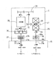
1.本装置(TDSG:Traction Drive starter Generator)1は、図2に示すように、トラクションドライブ無段変速機25、スタータと発電機を兼ねる電気式の回転機26、2つのワンウェイ・クラッチ27,28、2箇所の入力軸21,22、これらを繋ぐ第1および第2のギヤ列30,31およびこれらを収容するハウジング33を主な構成要素とする。ハウジング33が、図示しないボルトのような締結部材によりギヤボックス15に連結されている。回転機26の回転軸29は、回転機26の両端面26a、26bから軸方向の両側に突出しており、第1ギヤ列である増速ギヤ列30が回転軸29の一端部29aに接続され、第2ギヤ列であるアイドラギヤ列31が、回転軸29の他端部29bに接続されている。こうして、増速ギヤ列30とアイドラギヤ列31を回転機26の両側、つまり軸方向の一方の外方と他方の外方に配置することで、ハウジング33内のスペースのバランスよい利用を図っている。
1. As shown in FIG. 2, this device (TDSG: Traction Drive starter Generator) 1 includes a traction drive continuously
増速ギヤ列30は、回転機26と高圧側クラッチ27との間に接続され、アイドラギヤ列31は、回転機26と無段変速機25の間に接続されている。無段変速機25は低圧側クラッチ28に接続されている。
The speed increasing
2.エンジン10の高圧(HP)軸7に接続される高圧側入力軸(HP入力軸) 21は、高圧側ワンウエイ・クラッチ(スプラグ式、ローラー式等)27のインナーレース27aと繋がる。高圧側ワンウエイ・クラッチ(以下、HPクラッチという)27はインナーレース27a側の方が高速のときに空転する向きに設定されており、エンジンが自立運転に入って回転数が上昇すると自動的に遮断されて空転する。エンジン10の低圧(LP)軸8に接続される低圧側入力軸(LP入力軸) 22は、低圧側ワンウエイ・クラッチ28のアウターレース28bと繋がる。低圧側ワンウエイ・クラッチ(以下、LPクラッチという)28も、インナーレース28a側のほうが高速のときに空転する向きに設定されており、エンジン回転数が低いスタート時に自動的に遮断されて空転する。HPクラッチ27のアウターレース27bは、増速ギヤ列30を介して回転機26の回転軸29の一端部29aに接続されている。
2. A high pressure side input shaft (HP input shaft) 21 connected to the high pressure (HP)
3.始動発電装置1には始動制御装置61が設けられている。この始動制御装置61は、エンジン10を停止状態から起動するための装置であり、モータ制御回路62およびスタータ制御回路63を備えている。モータ制御回路62は、
スタータモードにおいて、外部の電源または航空機搭載のAPU(補助動力源)等である電源35からの電力を調整して回転機26に供給し、発電モードにおいて、回転機からの発電電力を調整して外部の電気負荷36に供給する。スタータ制御回路63は、高圧軸回転センサ65から入力される高圧軸回転速度に基づき、モータ制御回路62を制御するとともに、無段変速機25の制御器50を制御して、スタートモードで無段変速機25の減速比を最大値に固定させる。モータ制御回路62は、スタータモードで、予め設定された回転数上昇パターンで回転機26の回転速度を上昇させることにより、エンジン10を起動する。
3. The
In the starter mode, the power from the
4.エンジンスタート時は、回転機26は電源35からモータ制御回路62を介して給電されてスタータ・モーターとして作動し、HP入力軸21を経由して図1のエンジン10のHP軸7を回転させ、エンジン10をスタートする。図2の高圧軸回転センサ65からの回転速度信号に基づきHP軸7が一定回転に達したことがわかると、回転機26は、モータ制御回路62によって給電が停止され、徐々に減速して停止する(スタータ・カットオフ)が、このときまでにエンジン10は自立運転しているので、HP軸7の回転数は上昇し続ける。こうなるとHPクラッチ27は、インナーレース27aの方がアウターレース24bよりも高速になるので、自動的に遮断されて、アウターレース24bが空転する。(スタータモード)
4). When the engine is started, the rotating
5.図1のエンジン10の回転、すなわちHP軸7の回転がさらに上昇するにつれ、LP軸(ファン軸)8の回転が上昇し始める。LP入力軸22は、前述のとおり、図2のLPクラッチ28のアウターレース28bに繋がっている。一方、回転機26は、アイドラギヤ列31およびトラクションドライブ無段変速機25を経由して、LPクラッチ28のインナーレース28aに繋がっている。具体的には、アイドラギヤ列31がトラクションドライブ無段変速機25の出力側に連結され、この変速機25の入力側がLPクラッチ28のインナーレース28aに繋がっている。このとき、アウターレース28bの方がインナーレース28aよりも高速なので、LPクラッチ28は遮断状態にある。
5). As the rotation of the
6.上記4項でスターター・カットオフ後は、回転機26の回転低下とともにLPクラッチ28のインナーレース28aの回転も低下する。一方、5項でLPクラッチ28のアウターレース28bの回転は上昇していくので、両者が一致したところでLPクラッチ28が自動的に接続状態となり、エンジン10のLP軸8で回転機26が駆動され始める。
6). After the starter cut-off in the above item 4, the rotation of the
7.このとき、図3に示すように、スタータ制御回路63からの指令を受けた制御器50により、トラクションドライブ無段変速機25は最大減速モード(入力側に対し、出力側の速度が最低)となっている。上記5〜7項をトランジェント・モードと称す。
7). At this time, as shown in FIG. 3, the traction drive continuously
トラクションドライブ無段変速機25は、ダブルキャビティ型であり、各キャビティ41の軸方向外側に一対の入力ディスク42,42が配置され、軸方向内側に一対の出力ディスク43,43が配置されている。入力ディスク42は入力軸45に連結され、出力ディスク43は出力軸46に連結されている。入力ディスク42と出力ディスク43とは、その間に配置されたパワーローラ48により、潤滑油の流体摩擦を利用して回転連結される。パワーローラ48は周方向に間隔を空けて複数個が配置される。出力軸46には出力ギヤ47が結合されており、この出力ギヤ47が図1のアイドラギヤ列31に連結された中間ギヤ51に接続されている。図3のパワーローラ48の姿勢は制御器50によって制御され、入出力ディスク42,43間の速度比が無段で変更される。最大増速モードでは、パワーローラ48は図3に二点鎖線で示す姿勢となる。
The traction drive continuously
8.図1のエンジン10のLP軸8の回転速度が上昇し、グランドアイドル(地上運転時のアイドリング状態)に達すると、図2の無段変速機25による速度制御が開始され、制御器50により、LP軸8の回転速度が変化しても回転機26の回転速度が一定(例えば24000rpm)となるよう無段変速機25の出力軸47の回転速度が制御される。回転機26が所定速度に達すると発電が開始され、LP入力軸22の回転速度に拘らず一定周波数(発電機が2極の場合400Hz )の交流電力が外部の電気負荷36に供給される。(ジェネレータ・モード)なお、このモードにおいてはHPクラッチ27のアウターレース速度はインナーレース速度より遅くなるよう増速ギヤ列30のギヤ比が設定されているので、HPクラッチ27は空転しており、したがって、始動発電装置1は、LP軸8のみから駆動され、HP軸7の作動に影響を及ぼさない。
8). When the rotational speed of the
つぎに、始動発電装置1の動作を図4および図5にしたがって説明する。図4および図5では無段変速機25および回転機26から遮断されている部分を破線で示している。
Next, the operation of the starting
図4に示すエンジンスタート時(スタータ・モード)は回転機26がHP軸7のみを駆動してエンジンをスタートさせる。このとき、LPクラッチ28は空転するので、LP軸8は駆動されない。したがって、LP軸8に連結された巨大なファン9の回転による大きな抵抗の発生を避けることができるので、スタート時の所要動力が低減される。
When the engine is started (starter mode) shown in FIG. 4, the rotating
エンジン自立後は、図5に示すように、LP軸8からLP入力軸22、LPクラッチ28、無段変速機25およびアイドラギヤ列31を介して回転機26を駆動するが(ジェネレータ・モード)、HPクラッチ27は空転しているので、HP入力軸21とLP入力軸22とが干渉することはない。上記となるようなギヤ比の1例として、HP入力軸21側から見て、増速ギヤ列30(図示は遊星歯車であるが、並行軸でもよい)=1:3 、アイドラギヤ列31=1.34:1 (減速)、中間ギヤ51と変速機出力ギヤ47の間=2:1(減速)、無段変速機25の変速比1/√5 (減速)〜√5 /1(増速)(全変速比1:5 )とする。
After the engine self-supporting, as shown in FIG. 5, the
なお、上記を実施するため、無段変速機25の変速比は、スタータモード、およびトランジェントモードにおける変速制御開始までは、前述のとおり、スタータ制御回路63によって常に最大減速(LP入力側からみて出力ギヤ47が1/√5 となるLoモード(図3の実線))に固定される。
In order to carry out the above, the speed ratio of the continuously
図2の各軸の各モードにおける速度関係の一例を、図6に示す。
a)スタータモードにおいて、図2のスタータ制御回路63からの指令により、モータ制御回路62が作動して、回転機26をモーターとして作動させ、HP軸7を駆動し始める。モーター回転とともに、図6に示すHP軸回転数Aも上昇し、エンジンは自立運転を始める。
An example of the speed relationship in each mode of each axis in FIG. 2 is shown in FIG.
a) In the starter mode, the
b)HP軸7が例えば第1回転数である5500rpm に達すると、高圧軸回転センサ65からの回転数検出信号を受けたスタータ制御回路63が作動し、モータ制御回路62から回転機(モータ)26への給電がカット・オフ(給電停止)される。このときモーター回転数Bは16500rpm(ギヤ比より)である。モーター・カットオフに伴い、HPクラッチ・アウターレース速度Cが低下し、一方でHP軸速度Aは上昇するので、HPクラッチ27は空転する。
b) When the
c)LPクラッチ・インナーレース速度Dは、9項で示したギヤ比の関係および無段変速機25がLoモードに固定されていることより、エンジンスタート後から4000rpm (モーター・カットオフ)まで、モーター回転数Bに連動して回転数が上昇する。その後はモーター・カットオフにより他の軸と共に回転は急落する。
c) The LP clutch / inner race speed D is from 4000 rpm (motor cut-off) after the engine start, because of the gear ratio relationship shown in
d)LP軸回転数E(ファンに直結)はHP軸回転数Aに連動して上昇していく。これがLPクラッチ・インナーレース速度Dと合致したとき、例えばHP軸7が第2回転数である7500rpmに達したとき、LPクラッチ28が自動的に接続される。それ以降は、LP側入力軸22が無段変速機25を介して回転機26を駆動し始める。他方、HPクラッチ・アウターレース速度CはHP軸速度Aよりも十分低いので、HPクラッチ27は空転する。
d) The LP shaft rotation speed E (directly connected to the fan) increases in conjunction with the HP shaft rotation speed A. When this coincides with the LP clutch inner race speed D, for example, when the
e)HP軸速度Aはエンジンがグランドアイドルになると静定する(9000rpm)。他軸も同様に静定する。 e) HP shaft speed A is settled when the engine becomes a ground idle (9000 rpm). The other axes are settled in the same way.
f)静定後、図3のトラクションドライブ制御器50が起動し、図2の回転機26を一定回転数(24000rpm)に制御する。無段変速機25は、LP側軸回転数Eの4000rpm 〜20000rpmに対し、発電機(回転機)回転数Bを一定になるよう制御できる。回転機26は2極なので発電周波数は400Hzである。連動してHPクラッチ・アウターレース速度Cも8000rpm まで上昇するが、グランドアイドル時のHP軸回転数Aの9000rpm より遅いため、HPクラッチ27は空転したままである。
f) After settling, the
g)その後テイクオフに移ると、LP軸速度Eは20000rpmまで上昇するが、無段変速機25の速度制御範囲内なので、発電機速度である回転機速度Bは24000rpm一定に保たれている。一方、HP軸速度Aは15000rpmまで上昇するが、HPクラッチ・アウターレース速度Cは回転機速度Bに連動して一定の8000rpm に維持されるので、HPクラッチ27は空転のままである。
g) After that, when the take-off is started, the LP shaft speed E rises to 20000 rpm, but since it is within the speed control range of the continuously
異常発生時は、無段変速機25は制御器50によってLoモードに固定され、各回転軸速度を最低にし、安全を図る。
When an abnormality occurs, the continuously
図7の第2実施形態に示すように、クラッチ27,28、ギヤ列30,31はエンジン・アクセサリ・ギヤボックス15に内蔵し、無段変速機25と回転機26を、このギヤボックス15の外に配置して、それぞれ別々の変速機ハウジングH25と回転機ハウジングH26に収納し、両ハウジングH25,H26をギヤボックス15に連結する構造として、他のアクセサリと同列で扱ってもよい。
As shown in the second embodiment of FIG. 7, the
また、図8の第3実施形態に示すように、LPクラッチ28をアイドラギヤ列31と、無段変速機25、詳しくはその中間ギヤ51との間に設けてもよい。その場合、LPクラッチ28のインナーレース28aがアイドラギヤ列31に連結され、アウターレース28bが中間ギヤ51に連結される。
Further, as shown in the third embodiment of FIG. 8, the LP clutch 28 may be provided between the
図9の第4実施形態では、発電容量を大きくするために、本発明の始動発電装置(TDSG)1を複数、例えば2台設けている。両装置1,1からの発電出力を接触器55,56を介して電路57,58に供給する。一定周波数(CF)の電流が流れる両電路57,58間には遮断器60が接続されている。所要電力の大きさに応じて、接触器55,56を開閉することにより、一方の装置1の電力のみを使用する場合と、両方の装置1の電力を使用する場合とに切り換える。
In the fourth embodiment of FIG. 9, in order to increase the power generation capacity, a plurality of, for example, two starter power generation devices (TDSG) 1 of the present invention are provided. The power generation output from both
以上説明した本発明のポイントをまとめると、つぎのとおりである。
(1)航空機のエンジン・スタータと発電機を兼用する始動発電装置1であって、図2に示したスタータと発電機を兼ねる回転機26、変速機(例えばトラクションドライブ無段変速機)25、高圧側クラッチ27および低圧側クラッチ28を備え、エンジン10の高圧系と低圧系のそれぞれと結合し、エンジン・スタート時はモータ26が直接高圧系を駆動し、エンジン10が自立運転に入ったあとはエンジン10の低圧系が無段変速機25を駆動し、この無段変速機25がエンジン10からの入力回転数にかかわらず発電機26を一定回転速度で駆動する。
The points of the present invention described above are summarized as follows.
(1) A
(2)上記(1)となるように2つのクラッチ27,28、増速ギヤ列30およびアイドラギヤ列31を配置する。(高圧側クラッチ27はエンジン高圧軸7側が高速回転のとき空転し、低圧側クラッチ28は装置1側が高速回転のとき空転するように設定する。)
(2) The two
(3)スタート時は、制御器50により、無段変速機25が常にLoモード(最大減速モード)となるよう制御する。
(4)スタート時は常にエンジン低圧軸8の回転速度が装置1側よりも遅く、エンジン自立後は常にエンジン高圧軸7が装置1側よりも速い回転速度となるように、第1ギヤ列30および第2ギヤ列31の各ギヤ比を選定して各要素間を繋ぐ(無段変速機25はLoモード)。これにより、スタート時はファン9を回転させず、エンジン自立後はコア(高圧軸7)に影響を及ぼさない。
(3) At the start, the
(4) The
(5)回転機26の両側に、高圧側入出力ギヤ(増速ギヤ列30)と低圧側入出力ギヤ(アイドラギヤ列31)とを分けて配置して、スペースをバランスよく利用した。
(5) The high pressure side input / output gear (acceleration gear train 30) and the low pressure side input / output gear (idler gear train 31) are separately arranged on both sides of the rotating
(6)両クラッチ27,28はアクセサリ・ギヤボックス15内に配置してもよい(図7)。
(7)無段変速機25と回転機26は別々のハウジングH25,H26に収納してもよい(図7)。
(8)非常時は必ず無段変速機25がLoモードとなるように制御する。
(6) Both
(7) The continuously
(8) In an emergency, the continuously
以上説明したとおり、本発明によれば、図1の航空機エンジン10の図2に示す低圧軸8による一定周波数発電と、高圧軸7による電気式エンジンスタートが1台で行えるので、複数機器の搭載が必要でなくなる結果、航空機の電気システムの簡素化、コストダウンが実現する。さらに、全機を一定周波数発電で統一でき、航空機の電源システムの簡素化ができる。
また、エンジンスタート時は回転機26が高圧軸21のみを駆動してエンジン10をスタートさせ、このとき、低圧側クラッチ28は空転するので、低圧軸22は駆動されない。したがって、低圧軸22に連結される巨大なファン9(図1)のような負荷による大きな抵抗の発生を避けることができるので、スタート時の所要動力が低減される。
上記を通じ航空機の電動化を促進できる。
As described above, according to the present invention, the constant frequency power generation by the low-
Further, when the engine is started, the rotating
Through the above, electrification of aircraft can be promoted.
なお、無段変速機として、上記無段変速機25以外の、例えばベルト式変速機を使用してもよい。また、高圧側クラッチ27および低圧側クラッチ28の一方または両方として、ワンウエイクラッチに代えて、多板クラッチのような、外部からオン・オフ制御する非自動型のクラッチを使用してもよい。
For example, a belt-type transmission other than the continuously
以上のとおり、図面を参照しながら本発明の好適な実施形態を説明したが、本発明の趣旨を逸脱しない範囲内で、種々の追加、変更または削除が可能である。例えば、本発明は、ターボプロプエンジンとして使用するガスタービンエンジンにも適用できる。したがって、そのようなものも本発明の範囲内に含まれる。 As described above, the preferred embodiments of the present invention have been described with reference to the drawings, but various additions, modifications, or deletions can be made without departing from the spirit of the present invention. For example, the present invention can be applied to a gas turbine engine used as a turboprop engine. Therefore, such a thing is also included in the scope of the present invention.
1 始動発電装置
7 高圧軸
8 低圧軸
10 エンジン
15 ギヤボックス
16 伝達ギヤ列
21 高圧側入力軸
22 低圧側入力軸
25 トラクションドライブ無段変速機
26 回転機
27 高圧側ワンウエイ・クラッチ
28 低圧側ワンウエイ・クラッチ
30 増速ギヤ列(第1ギヤ列)
31 アイドラギヤ列(第2ギヤ列)
33 ハウジング
H25 変速機ハウジング
H26 回転機ハウジング
DESCRIPTION OF
31 idler gear train (second gear train)
33 Housing H25 Transmission housing H26 Rotating machine housing
Claims (6)
スタータと発電機を兼ねる電気式回転機、無段変速機、前記エンジンの高圧軸に連結される高圧側クラッチ、および低圧軸に連結される低圧側クラッチを備え、
スタート時は前記回転機が前記高圧側クラッチを介して前記高圧軸を駆動し、前記エンジンが自立運転に入った後は前記低圧軸が前記低圧側クラッチおよび前記無段変速機を介して前記回転機を一定回転数で駆動し、
前記高圧側クラッチは、前記高圧軸が第1回転速度に達したときに遮断され、前記低圧側クラッチは、前記高圧軸が前記第1回転速度よりも高い第2回転速度に達したとき接続されるように設定されており、
前記回転機の一端部と前記高圧側クラッチとが第1のギヤ列を介して連結され、前記回転機の他端部と前記低圧軸とが第2のギヤ列および前記無段変速機を介して連結され、スタート時は常に前記エンジン低圧軸の回転速度が装置側よりも遅く、エンジン自立後は常に前記エンジン高圧軸が装置側よりも速い回転速度となるように、前記第1ギヤ列および前記第2ギヤ列の各ギヤ比が選定されており、
さらに、前記回転機、前記無段変速機、前記高圧側クラッチ、前記低圧側クラッチ、第1のギヤ列および第2のギヤ列を収納するハウジングを備え、前記ハウジングが、前記高圧軸および低圧軸に連結された伝達ギヤ列を収納したギヤボックスに連結されている航空機用始動発電装置。 A device used in a two-shaft gas turbine engine for an aircraft,
An electric rotating machine that doubles as a starter and a generator, a continuously variable transmission, a high-pressure side clutch connected to the high-pressure shaft of the engine, and a low-pressure side clutch connected to the low-pressure shaft;
At the start, the rotating machine drives the high-pressure shaft through the high-pressure side clutch, and after the engine enters a self-sustaining operation, the low-pressure shaft rotates through the low-pressure side clutch and the continuously variable transmission. Drive the machine at a constant speed ,
The high-pressure side clutch is disconnected when the high-pressure shaft reaches the first rotation speed, and the low-pressure side clutch is connected when the high-pressure shaft reaches a second rotation speed higher than the first rotation speed. Is set to
One end of the rotating machine and the high-pressure side clutch are connected via a first gear train, and the other end of the rotating machine and the low-pressure shaft are connected via a second gear train and the continuously variable transmission. The first gear train and the engine low-pressure shaft always have a lower rotational speed than the apparatus side at the start, and the engine high-pressure shaft always has a higher rotational speed than the apparatus side after the engine is independent. Each gear ratio of the second gear train is selected,
And a housing that houses the rotating machine, the continuously variable transmission, the high-pressure side clutch, the low-pressure side clutch, the first gear train, and the second gear train, the housing comprising the high-pressure shaft and the low-pressure shaft. An aircraft starter generator connected to a gear box containing a transmission gear train connected to the aircraft.
Priority Applications (4)
| Application Number | Priority Date | Filing Date | Title |
|---|---|---|---|
| JP2010142267A JP5016706B2 (en) | 2009-11-04 | 2010-06-23 | Aircraft starter generator |
| CA2719626A CA2719626C (en) | 2009-11-04 | 2010-11-01 | Aircraft starter generator |
| US12/916,898 US8500583B2 (en) | 2009-11-04 | 2010-11-01 | Aircraft starter generator |
| EP10189724.7A EP2320067B1 (en) | 2009-11-04 | 2010-11-02 | Aircraft starter generator |
Applications Claiming Priority (3)
| Application Number | Priority Date | Filing Date | Title |
|---|---|---|---|
| JP2009253400 | 2009-11-04 | ||
| JP2009253400 | 2009-11-04 | ||
| JP2010142267A JP5016706B2 (en) | 2009-11-04 | 2010-06-23 | Aircraft starter generator |
Publications (2)
| Publication Number | Publication Date |
|---|---|
| JP2011117437A JP2011117437A (en) | 2011-06-16 |
| JP5016706B2 true JP5016706B2 (en) | 2012-09-05 |
Family
ID=43479292
Family Applications (1)
| Application Number | Title | Priority Date | Filing Date |
|---|---|---|---|
| JP2010142267A Active JP5016706B2 (en) | 2009-11-04 | 2010-06-23 | Aircraft starter generator |
Country Status (4)
| Country | Link |
|---|---|
| US (1) | US8500583B2 (en) |
| EP (1) | EP2320067B1 (en) |
| JP (1) | JP5016706B2 (en) |
| CA (1) | CA2719626C (en) |
Families Citing this family (61)
| Publication number | Priority date | Publication date | Assignee | Title |
|---|---|---|---|---|
| US8169100B2 (en) * | 2008-01-30 | 2012-05-01 | Pratt & Whitney Canada Corp. | Torque transmission for an aircraft engine |
| US8181442B2 (en) * | 2008-05-05 | 2012-05-22 | Pratt & Whitney Canada Corp. | Gas turbine aircraft engine with power variability |
| US8561503B2 (en) * | 2011-07-28 | 2013-10-22 | Hamilton Sundstrand Corporation | Motor-generator and prime mover gearing assembly |
| US8723385B2 (en) | 2011-10-07 | 2014-05-13 | General Electric Company | Generator |
| US8723349B2 (en) | 2011-10-07 | 2014-05-13 | General Electric Company | Apparatus for generating power from a turbine engine |
| AU2012354937A1 (en) * | 2011-12-22 | 2014-07-10 | Kawasaki Jukogyo Kabushiki Kaisha | Gas turbine engine and method for starting same |
| US8554433B2 (en) * | 2012-01-04 | 2013-10-08 | General Electric Company | Apparatus for driving shaft rotation and method |
| US20130232941A1 (en) * | 2012-03-07 | 2013-09-12 | Ge Aviation Systems Llc | Apparatus for extracting input power from the low pressure spool of a turbine engine |
| US8876650B2 (en) * | 2012-03-30 | 2014-11-04 | Hamilton Sundstrand Corporation | Aircraft accessory drive multiple speed transmission |
| JP5568596B2 (en) | 2012-05-30 | 2014-08-06 | 川崎重工業株式会社 | Aircraft engine gearbox integrated power generator |
| US9045996B2 (en) | 2012-11-20 | 2015-06-02 | Honeywell International Inc. | Gas turbine engine optimization by electric power transfer |
| WO2014130148A1 (en) * | 2013-02-24 | 2014-08-28 | Rolls-Royce Corporation | Combined cycle power plant |
| US9752500B2 (en) * | 2013-03-14 | 2017-09-05 | Pratt & Whitney Canada Corp. | Gas turbine engine with transmission and method of adjusting rotational speed |
| JP6056982B2 (en) * | 2013-09-25 | 2017-01-11 | 株式会社Ihi | Fuel system |
| WO2015046177A1 (en) * | 2013-09-25 | 2015-04-02 | 株式会社Ihi | Fuel system |
| US9765747B2 (en) * | 2013-12-11 | 2017-09-19 | Schaeffler Technologies AG & Co. KG | Starter return mechanism |
| CN103670718B (en) * | 2013-12-12 | 2015-10-21 | 中国南方航空工业(集团)有限公司 | The electric starting controlling method of gas turbine and device |
| FR3020838B1 (en) * | 2014-05-07 | 2019-10-18 | Safran Aircraft Engines | ENGINE GAS TURBINE ENGINE WITH LOW PRESSURE BODY |
| US9613539B1 (en) * | 2014-08-19 | 2017-04-04 | Amazon Technologies, Inc. | Damage avoidance system for unmanned aerial vehicle |
| GB201506396D0 (en) * | 2014-12-11 | 2015-05-27 | Rolls Royce Plc | Cabin blower system |
| GB201508545D0 (en) | 2015-05-19 | 2015-07-01 | Rolls Royce Plc | Compressor tip injector |
| GB2541185A (en) * | 2015-08-07 | 2017-02-15 | Rolls Royce Plc | Auxiliary power unit assembly and a method of using the same |
| US10495003B1 (en) * | 2016-07-05 | 2019-12-03 | Hamilton Sunstrand Corporation | Gas turbine engine starter reduction gear train with jacking and planetary geared transmission |
| US10330016B2 (en) | 2016-07-05 | 2019-06-25 | Hamilton Sundstrand Corporation | Gas turbine engine starter reduction gear train with stacked planetary gear systems |
| US10473034B2 (en) | 2016-07-05 | 2019-11-12 | Hamilton Sundstrand Corporation | Gas turbine engine starter reduction gear train with geared rotary actuator |
| US11415063B2 (en) | 2016-09-15 | 2022-08-16 | Pratt & Whitney Canada Corp. | Reverse-flow gas turbine engine |
| US10883424B2 (en) | 2016-07-19 | 2021-01-05 | Pratt & Whitney Canada Corp. | Multi-spool gas turbine engine architecture |
| PL3273032T3 (en) * | 2016-07-19 | 2020-04-30 | Pratt & Whitney Canada Corp. | A multi-spool gas turbine engine architecture |
| US20180045119A1 (en) * | 2016-08-09 | 2018-02-15 | United Technologies Corporation | Geared turbofan with low spool power extraction |
| US10746181B2 (en) * | 2016-08-22 | 2020-08-18 | Raytheon Technologies Corporation | Variable speed boost compressor for gas turbine engine cooling air supply |
| US11035293B2 (en) | 2016-09-15 | 2021-06-15 | Pratt & Whitney Canada Corp. | Reverse flow gas turbine engine with offset RGB |
| US10465611B2 (en) | 2016-09-15 | 2019-11-05 | Pratt & Whitney Canada Corp. | Reverse flow multi-spool gas turbine engine with aft-end accessory gearbox drivingly connected to both high pressure spool and low pressure spool |
| US10815899B2 (en) | 2016-11-15 | 2020-10-27 | Pratt & Whitney Canada Corp. | Gas turbine engine accessories arrangement |
| US10526975B2 (en) * | 2016-11-30 | 2020-01-07 | The Boeing Company | Power extraction system and method for a gas turbine engine of a vehicle |
| US20180171815A1 (en) * | 2016-12-16 | 2018-06-21 | United Technologies Corporation | Traction drive transmission for gas turbine engine accessory gearbox |
| US10422243B2 (en) * | 2017-01-19 | 2019-09-24 | United Technologies Corporation | Gas turbine engine dual towershaft accessory gearbox and starter generator assembly |
| US10808624B2 (en) | 2017-02-09 | 2020-10-20 | Pratt & Whitney Canada Corp. | Turbine rotor with low over-speed requirements |
| US10738709B2 (en) | 2017-02-09 | 2020-08-11 | Pratt & Whitney Canada Corp. | Multi-spool gas turbine engine |
| US10746188B2 (en) | 2017-03-14 | 2020-08-18 | Pratt & Whitney Canada Corp. | Inter-shaft bearing connected to a compressor boost system |
| US10215052B2 (en) | 2017-03-14 | 2019-02-26 | Pratt & Whitney Canada Corp. | Inter-shaft bearing arrangement |
| US10358981B2 (en) | 2017-04-11 | 2019-07-23 | United Technologies Corporation | High and low spool accessory gearbox drive |
| JP6725894B2 (en) | 2017-11-13 | 2020-07-22 | 株式会社Ihi | Turbo fan engine |
| US10563591B2 (en) * | 2018-01-17 | 2020-02-18 | United Technologies Corporation | Systems and methods of low spool power extraction |
| US10954865B2 (en) * | 2018-06-19 | 2021-03-23 | The Boeing Company | Pressurized air systems for aircraft and related methods |
| US10934972B2 (en) * | 2018-07-19 | 2021-03-02 | Raytheon Technologies Corporation | Stability margin and clearance control using power extraction and assist of a gas turbine engine |
| PL3653859T3 (en) | 2018-08-08 | 2024-05-27 | Pratt & Whitney Canada Corp. | Multi-engine system and method |
| US10634064B1 (en) * | 2018-10-11 | 2020-04-28 | United Technologies Corporation | Accessory gearbox with superposition gearbox |
| US11261795B2 (en) | 2018-10-18 | 2022-03-01 | Rolls-Royce North American Technologies, Inc. | Dual mode starter generator |
| US11015532B2 (en) | 2018-10-18 | 2021-05-25 | Rolls-Royce North American Technologies, Inc. | Parallel starter/generator and air turbine starter |
| US20220010733A1 (en) * | 2018-11-19 | 2022-01-13 | Kawasaki Jukogyo Kabushiki Kaisha | Electric power generating apparatus for use in aircraft |
| US11168617B2 (en) | 2019-01-30 | 2021-11-09 | Raytheon Technologies Corporation | Electric enhanced transmission for multi-spool load-sharing turbofan engine |
| US11408353B2 (en) | 2019-03-28 | 2022-08-09 | Honeywell International Inc. | Auxiliary power unit with plural spool assembly and starter transmission arrangement |
| US10903720B2 (en) | 2019-04-09 | 2021-01-26 | Rolls-Royce Corporation | Starter/generator electrical joint |
| US20200325821A1 (en) | 2019-04-09 | 2020-10-15 | Rolls-Royce North American Technologies Inc. | Starter/generator |
| US11333077B2 (en) | 2019-05-06 | 2022-05-17 | The Boeing Company | Systems and methods for transferring mechanical power in a turbine engine |
| US11193425B2 (en) * | 2019-06-19 | 2021-12-07 | Raytheon Technologies Corporation | Gearbox for boost spool turbine engine |
| US11220960B2 (en) * | 2019-10-03 | 2022-01-11 | Raytheon Technologies Corporation | Superposition gearbox for engine performance |
| US11248523B2 (en) | 2019-11-06 | 2022-02-15 | Raytheon Technologies Corporation | Dual clutch transmission for accessory gearbox drive |
| GB202007576D0 (en) | 2020-05-21 | 2020-07-08 | Rolls Royce Plc | Aircraft cabin blower system |
| US12037913B2 (en) * | 2020-11-02 | 2024-07-16 | Ge Avio S.R.L. | Electric machine assembly for a turbine engine |
| CN113266468B (en) * | 2021-06-22 | 2022-06-21 | 合肥工业大学 | Hybrid electric propulsion method and device for three-shaft gas turbine engine |
Family Cites Families (21)
| Publication number | Priority date | Publication date | Assignee | Title |
|---|---|---|---|---|
| US3274855A (en) | 1962-06-19 | 1966-09-27 | Sundstrand Corp | Starter-drive system |
| GB1199145A (en) | 1966-09-02 | 1970-07-15 | English Electric Co Ltd | Rotary Transmission System |
| US3786696A (en) * | 1972-09-11 | 1974-01-22 | Sundstrand Corp | Starter-drive |
| US4315442A (en) | 1980-02-15 | 1982-02-16 | Sundstrand Corporation | Aircraft generator starter-drive |
| US4743776A (en) | 1986-09-02 | 1988-05-10 | Sundstrand Corporation | Starter-generator for engines |
| US5890468A (en) * | 1994-01-25 | 1999-04-06 | Komatsu Ltd. | Differential driving supercharger and method for controlling the same |
| JPH09144557A (en) * | 1995-11-24 | 1997-06-03 | Mitsubishi Heavy Ind Ltd | Gas turbine plant |
| JP4146049B2 (en) | 1999-10-05 | 2008-09-03 | 本田技研工業株式会社 | Control device for aircraft gas turbine engine |
| JP2001193476A (en) * | 2000-01-14 | 2001-07-17 | Ishikawajima Harima Heavy Ind Co Ltd | Device and method for starting multi-shaft gas turbine |
| JP2007519848A (en) * | 2004-01-30 | 2007-07-19 | プラット アンド ホイットニー カナダ コーポレイション | Compact structure for attaching fuel pumps and other accessories to the accessory gearbox |
| US20070022735A1 (en) * | 2005-07-29 | 2007-02-01 | General Electric Company | Pto assembly for a gas turbine engine |
| FR2892456B1 (en) * | 2005-10-21 | 2008-01-04 | Hispano Suiza Sa | DEVICE FOR DRIVING ACCESSORY MACHINES OF A GAS TURBINE ENGINE |
| US20070265761A1 (en) * | 2006-05-11 | 2007-11-15 | Dooley Kevin A | Electric power generation system and method |
| JP4551916B2 (en) * | 2006-07-12 | 2010-09-29 | 川崎重工業株式会社 | Power generation / starter device with traction transmission mechanism |
| US7997085B2 (en) * | 2006-09-27 | 2011-08-16 | General Electric Company | Gas turbine engine assembly and method of assembling same |
| EP2126312B1 (en) * | 2006-12-19 | 2010-12-08 | Renault Trucks | Power unit for an automotive vehicle and vehicle including such a power unit |
| WO2008082335A1 (en) * | 2006-12-29 | 2008-07-10 | Volvo Aero Corporation | A power transmission device for a gas turbine engine |
| JP4954819B2 (en) | 2007-07-23 | 2012-06-20 | リコー光学株式会社 | Blood vessel image input device and blood vessel image reading device |
| US8146370B2 (en) * | 2008-05-21 | 2012-04-03 | Honeywell International Inc. | Turbine drive system with lock-up clutch and method |
| JP4700113B2 (en) | 2009-02-06 | 2011-06-15 | 川崎重工業株式会社 | Aircraft generator |
| JP4435858B1 (en) * | 2009-04-30 | 2010-03-24 | 日産自動車株式会社 | Control device and control method for belt type continuously variable transmission |
-
2010
- 2010-06-23 JP JP2010142267A patent/JP5016706B2/en active Active
- 2010-11-01 CA CA2719626A patent/CA2719626C/en active Active
- 2010-11-01 US US12/916,898 patent/US8500583B2/en active Active
- 2010-11-02 EP EP10189724.7A patent/EP2320067B1/en active Active
Also Published As
| Publication number | Publication date |
|---|---|
| EP2320067A2 (en) | 2011-05-11 |
| CA2719626C (en) | 2014-04-01 |
| CA2719626A1 (en) | 2011-05-04 |
| US8500583B2 (en) | 2013-08-06 |
| EP2320067B1 (en) | 2018-08-22 |
| JP2011117437A (en) | 2011-06-16 |
| US20110101693A1 (en) | 2011-05-05 |
| EP2320067A3 (en) | 2016-03-30 |
Similar Documents
| Publication | Publication Date | Title |
|---|---|---|
| JP5016706B2 (en) | Aircraft starter generator | |
| JP5048299B2 (en) | Extraction device for mechanical output between HP and LP shafts of a twin shaft turbine engine | |
| US10851714B2 (en) | Engine accessory drives systems and methods | |
| US7168913B2 (en) | Twin-spool turbojet with means for driving ancillary machines | |
| CA2955506C (en) | Oil system for turbine engine and related method | |
| RU2429360C2 (en) | System of driving two-stage turbine engine auxiliary mechanism and method of operating said system (versions) | |
| EP2128389B1 (en) | A gas turbine engine arrangement | |
| US6732529B2 (en) | Off loading clutch for gas turbine engine starting | |
| US7434406B2 (en) | Drive for using a direct driven generator to start a counter-rotating multi-spool gas turbine engine | |
| US8169100B2 (en) | Torque transmission for an aircraft engine | |
| RU2352800C2 (en) | Method and system to generate power to drive engine auxiliary components | |
| US7973422B2 (en) | Device for producing electrical power in a two-spool gas turbine engine | |
| JP6755860B2 (en) | Detachable restart packs for turboshaft engines, multi-engine helicopter propulsion system structures with such packs, and corresponding helicopters | |
| CN109219695B (en) | Aircraft turbine engine with planetary or epicyclic reduction gear | |
| WO2008082335A1 (en) | A power transmission device for a gas turbine engine | |
| WO2008082336A1 (en) | A power transmission device for a gas turbine engine, an aeroplane and a method for operating a gas turbine engine | |
| US20170074169A1 (en) | Gas turbine engine comprising a starter engaged with a low-pressure body | |
| WO2008044973A1 (en) | A device for and a method of starting a gas turbine engine | |
| WO2008082334A1 (en) | A gas turbine engine, an aircraft provided therewith, and a method of controlling the operation of such an engine | |
| US11415061B2 (en) | Power distribution device between an electric starter and an electric machine towards a shaft of a turbomachine | |
| EP4197912A1 (en) | Pumping system | |
| US12116899B2 (en) | Variable speed pumping system with electric pump motor generator |
Legal Events
| Date | Code | Title | Description |
|---|---|---|---|
| A977 | Report on retrieval |
Free format text: JAPANESE INTERMEDIATE CODE: A971007 Effective date: 20111020 |
|
| A131 | Notification of reasons for refusal |
Free format text: JAPANESE INTERMEDIATE CODE: A131 Effective date: 20111101 |
|
| A521 | Request for written amendment filed |
Free format text: JAPANESE INTERMEDIATE CODE: A523 Effective date: 20111228 |
|
| TRDD | Decision of grant or rejection written | ||
| A01 | Written decision to grant a patent or to grant a registration (utility model) |
Free format text: JAPANESE INTERMEDIATE CODE: A01 Effective date: 20120529 |
|
| A01 | Written decision to grant a patent or to grant a registration (utility model) |
Free format text: JAPANESE INTERMEDIATE CODE: A01 |
|
| A61 | First payment of annual fees (during grant procedure) |
Free format text: JAPANESE INTERMEDIATE CODE: A61 Effective date: 20120608 |
|
| FPAY | Renewal fee payment (event date is renewal date of database) |
Free format text: PAYMENT UNTIL: 20150615 Year of fee payment: 3 |
|
| R150 | Certificate of patent or registration of utility model |
Ref document number: 5016706 Country of ref document: JP Free format text: JAPANESE INTERMEDIATE CODE: R150 Free format text: JAPANESE INTERMEDIATE CODE: R150 |
|
| R250 | Receipt of annual fees |
Free format text: JAPANESE INTERMEDIATE CODE: R250 |
|
| R250 | Receipt of annual fees |
Free format text: JAPANESE INTERMEDIATE CODE: R250 |