EP2320067A2 - Aircraft starter generator - Google Patents
Aircraft starter generator Download PDFInfo
- Publication number
- EP2320067A2 EP2320067A2 EP10189724A EP10189724A EP2320067A2 EP 2320067 A2 EP2320067 A2 EP 2320067A2 EP 10189724 A EP10189724 A EP 10189724A EP 10189724 A EP10189724 A EP 10189724A EP 2320067 A2 EP2320067 A2 EP 2320067A2
- Authority
- EP
- European Patent Office
- Prior art keywords
- rotating shaft
- clutch
- rotating machine
- rotating
- shaft
- Prior art date
- Legal status (The legal status is an assumption and is not a legal conclusion. Google has not performed a legal analysis and makes no representation as to the accuracy of the status listed.)
- Granted
Links
- 239000007858 starting material Substances 0.000 title claims abstract description 69
- 230000005540 biological transmission Effects 0.000 claims abstract description 53
- 239000000567 combustion gas Substances 0.000 claims description 2
- 239000000446 fuel Substances 0.000 claims description 2
- 230000007423 decrease Effects 0.000 description 4
- 238000004519 manufacturing process Methods 0.000 description 3
- 238000010248 power generation Methods 0.000 description 3
- 239000007789 gas Substances 0.000 description 2
- 230000001052 transient effect Effects 0.000 description 2
- 238000010586 diagram Methods 0.000 description 1
- 238000005516 engineering process Methods 0.000 description 1
- 239000000314 lubricant Substances 0.000 description 1
- 238000000034 method Methods 0.000 description 1
- 238000012986 modification Methods 0.000 description 1
- 230000004048 modification Effects 0.000 description 1
Images


Classifications
-
- F—MECHANICAL ENGINEERING; LIGHTING; HEATING; WEAPONS; BLASTING
- F02—COMBUSTION ENGINES; HOT-GAS OR COMBUSTION-PRODUCT ENGINE PLANTS
- F02N—STARTING OF COMBUSTION ENGINES; STARTING AIDS FOR SUCH ENGINES, NOT OTHERWISE PROVIDED FOR
- F02N11/00—Starting of engines by means of electric motors
- F02N11/04—Starting of engines by means of electric motors the motors being associated with current generators
-
- F—MECHANICAL ENGINEERING; LIGHTING; HEATING; WEAPONS; BLASTING
- F02—COMBUSTION ENGINES; HOT-GAS OR COMBUSTION-PRODUCT ENGINE PLANTS
- F02C—GAS-TURBINE PLANTS; AIR INTAKES FOR JET-PROPULSION PLANTS; CONTROLLING FUEL SUPPLY IN AIR-BREATHING JET-PROPULSION PLANTS
- F02C7/00—Features, components parts, details or accessories, not provided for in, or of interest apart form groups F02C1/00 - F02C6/00; Air intakes for jet-propulsion plants
- F02C7/26—Starting; Ignition
- F02C7/268—Starting drives for the rotor, acting directly on the rotor of the gas turbine to be started
- F02C7/275—Mechanical drives
-
- F—MECHANICAL ENGINEERING; LIGHTING; HEATING; WEAPONS; BLASTING
- F02—COMBUSTION ENGINES; HOT-GAS OR COMBUSTION-PRODUCT ENGINE PLANTS
- F02C—GAS-TURBINE PLANTS; AIR INTAKES FOR JET-PROPULSION PLANTS; CONTROLLING FUEL SUPPLY IN AIR-BREATHING JET-PROPULSION PLANTS
- F02C7/00—Features, components parts, details or accessories, not provided for in, or of interest apart form groups F02C1/00 - F02C6/00; Air intakes for jet-propulsion plants
- F02C7/36—Power transmission arrangements between the different shafts of the gas turbine plant, or between the gas-turbine plant and the power user
-
- F—MECHANICAL ENGINEERING; LIGHTING; HEATING; WEAPONS; BLASTING
- F02—COMBUSTION ENGINES; HOT-GAS OR COMBUSTION-PRODUCT ENGINE PLANTS
- F02N—STARTING OF COMBUSTION ENGINES; STARTING AIDS FOR SUCH ENGINES, NOT OTHERWISE PROVIDED FOR
- F02N15/00—Other power-operated starting apparatus; Component parts, details, or accessories, not provided for in, or of interest apart from groups F02N5/00 - F02N13/00
- F02N15/02—Gearing between starting-engines and started engines; Engagement or disengagement thereof
- F02N15/022—Gearing between starting-engines and started engines; Engagement or disengagement thereof the starter comprising an intermediate clutch
-
- F—MECHANICAL ENGINEERING; LIGHTING; HEATING; WEAPONS; BLASTING
- F02—COMBUSTION ENGINES; HOT-GAS OR COMBUSTION-PRODUCT ENGINE PLANTS
- F02N—STARTING OF COMBUSTION ENGINES; STARTING AIDS FOR SUCH ENGINES, NOT OTHERWISE PROVIDED FOR
- F02N15/00—Other power-operated starting apparatus; Component parts, details, or accessories, not provided for in, or of interest apart from groups F02N5/00 - F02N13/00
- F02N15/02—Gearing between starting-engines and started engines; Engagement or disengagement thereof
- F02N15/04—Gearing between starting-engines and started engines; Engagement or disengagement thereof the gearing including disengaging toothed gears
- F02N15/043—Gearing between starting-engines and started engines; Engagement or disengagement thereof the gearing including disengaging toothed gears the gearing including a speed reducer
-
- F—MECHANICAL ENGINEERING; LIGHTING; HEATING; WEAPONS; BLASTING
- F02—COMBUSTION ENGINES; HOT-GAS OR COMBUSTION-PRODUCT ENGINE PLANTS
- F02D—CONTROLLING COMBUSTION ENGINES
- F02D2400/00—Control systems adapted for specific engine types; Special features of engine control systems not otherwise provided for; Power supply, connectors or cabling for engine control systems
- F02D2400/08—Redundant elements, e.g. two sensors for measuring the same parameter
-
- F—MECHANICAL ENGINEERING; LIGHTING; HEATING; WEAPONS; BLASTING
- F02—COMBUSTION ENGINES; HOT-GAS OR COMBUSTION-PRODUCT ENGINE PLANTS
- F02N—STARTING OF COMBUSTION ENGINES; STARTING AIDS FOR SUCH ENGINES, NOT OTHERWISE PROVIDED FOR
- F02N15/00—Other power-operated starting apparatus; Component parts, details, or accessories, not provided for in, or of interest apart from groups F02N5/00 - F02N13/00
- F02N15/02—Gearing between starting-engines and started engines; Engagement or disengagement thereof
- F02N15/04—Gearing between starting-engines and started engines; Engagement or disengagement thereof the gearing including disengaging toothed gears
- F02N15/043—Gearing between starting-engines and started engines; Engagement or disengagement thereof the gearing including disengaging toothed gears the gearing including a speed reducer
- F02N15/046—Gearing between starting-engines and started engines; Engagement or disengagement thereof the gearing including disengaging toothed gears the gearing including a speed reducer of the planetary type
-
- Y—GENERAL TAGGING OF NEW TECHNOLOGICAL DEVELOPMENTS; GENERAL TAGGING OF CROSS-SECTIONAL TECHNOLOGIES SPANNING OVER SEVERAL SECTIONS OF THE IPC; TECHNICAL SUBJECTS COVERED BY FORMER USPC CROSS-REFERENCE ART COLLECTIONS [XRACs] AND DIGESTS
- Y02—TECHNOLOGIES OR APPLICATIONS FOR MITIGATION OR ADAPTATION AGAINST CLIMATE CHANGE
- Y02T—CLIMATE CHANGE MITIGATION TECHNOLOGIES RELATED TO TRANSPORTATION
- Y02T50/00—Aeronautics or air transport
- Y02T50/60—Efficient propulsion technologies, e.g. for aircraft
Definitions
- the present invention relates to an aircraft starter generator which is drivingly connected to an aircraft engine to carry on two reverse operations - engine starter (motor) and generator.
- the aircraft starter generator is driven by a high-pressure rotating shaft of the two-shaft jet engine.
- this fails to accommodate an increase of electric power to be supplied to a huge number of electronic devices newly installed in the aircraft, which results in a higher risk for engine stall at lower output operations of the engine such as ground idling or descending flight.
- a future higher bypass ratio of the engine will increase that risk which may not be eliminated by the conventional constant frequency (CF) or variable frequency (VF) integrated drive generator (IDG) which incorporates a continuously variable transmission allowing to generate electric power with a constant frequency irrespective of the rotation number of the engine.
- CF constant frequency
- VF variable frequency
- the electric starter which may be replaced by the conventional air compressor starter.
- the electric starter because it can be used as a power generator after the engine is started, will contribute to its weight and cost saving.
- the starter generator since the compressor is driven by the high-pressure shaft, the starter generator is required to be connected to the high-pressure shaft in order to start the engine, which may result in the engine stall.
- the electric power generated by the generator has a variable frequency.
- JP (A) 2008-38902 discloses to modify the conventional IDG to work as a starter generator drivingly connected to the high-pressure rotating shaft, rather than the low-pressure rotating shaft.
- Another technique may be employed to modify the integrated drive generator and connect it to the high-pressure rotating shaft .
- this requires the traction drive to transmit a large torque at the start of the engine, which may cause unwanted heat-fusing and/or metallic fatigue in the contact surfaces of the traction drive.
- the present invention is to provide an aircraft starter generator in which an electric power with constant frequency is generated and a starter operation is carried out by the use of the high-pressure rotating shaft, which simplifies the structure of the apparatus and attains a cost reduction of the starter generator.
- the present invention provides a starter generator for use with an engine.
- the engine has a compressor for compressing air, a combustor for combusting fuel with the air compressed by the compressor, first and second turbines adapted to be rotated by impingements of compressed combustion gases from the combustor, a first rotating shaft drivingly connected with the compressor and the first turbine so that it rotates with the compressor and the first turbine, and a second rotating shaft drivingly connected with the second turbine so that it rotates with the second turbine.
- the starter generator has an electric rotating machine having a rotating shaft, the rotating machine being designed to carry on two reverse operations- motor and generator; a first clutch connected between the rotating machine and the first rotating shaft for transmitting rotations of the rotating machine to the first rotating shaft; a second clutch connected between the rotating machine and the second rotating shaft for transmitting rotations of the second rotating shaft to the rotating machine; a continuously variable transmission for changing the number of rotations transmitted from the second rotating shaft to the rotating machine; and a control designed to carry our a first mode in which the rotating machine is supplied with electric power to rotate the rotating shaft and thereby rotations of the rotating shaft are transmitted through the first clutch to the first rotating shaft and a second mode in which, following the first mode, the number of rotations of the rotating shaft of the rotating machine is kept constant by controlling a transmission ratio of the continuously variable transmission.
- the electric power generation of a constant frequency and the starting operation of the engine are carried out by the single rotating machine, which simplifies the structure of the starter generator and reduces its production cost. Also, when starting the engine, no load is transmitted to the rotating machine, which reduces an electric power needed for staring the engine.
- Fig. 1 is a schematic cross sectional view showing an aircraft engine and a starter generator drivingly connected to the engine, according to an embodiment of the invention
- Fig. 2 is a schematic cross sectional view of the aircraft starter generator shown in Fig. 1 ;
- Fig. 3 is a schematic cross sectional view of a traction drive incorporated in the starter generator shown in Fig. 2 ;
- Fig. 4 is a schematic cross sectional view of the aircraft starter generator in the starter mode
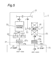
- Fig. 5 is a schematic cross sectional view of the aircraft starter generator in the generation mode
- Fig. 6 is a graph showing a time versus rotation number relationship of each rotating members in the aircraft starter generator
- Fig. 7 is a schematic cross sectional view of the aircraft starter generator according to the second embodiment
- Fig. 8 is a schematic cross sectional view of the aircraft starter generator according to the third embodiment.
- Fig. 9 is a block diagram of the aircraft starter generator according to the forth embodiment.
- Fig. 1 shows an aircraft engine generally indicated by reference numeral 10.
- the engine 10 is a gas turbine incorporated in the aircraft jet engine.
- the engine is a two-shaft turbo fan engine and has a compressor 2, a plurality of combustors 3, a high-pressure turbine 4 and a low-pressure turbine 5.
- the high-pressure turbine 4 is drivingly connected to the compressor 2 through a first rotating shaft or high-pressure shaft 7 to drive the compressor 2.
- the low-pressure turbine 4 which is used to transmit drive power to a load, is connected to a fan 9 through a second rotating shaft or low-pressure shaft 8 for rotating the fan.
- the high- and low-pressure shafts, 7 and 8 are connected through a gear train, generally indicated by reference numeral 11, to high- and low-pressure transmission shafts, 12 and 13, respectively.
- the shafts 12 and 13 are in turn connected through another gear train 16 accommodated in a gear box 15 to high- and low-pressure rotating shafts 21 and 22, respectively.
- the shafts 21 and 22 are connected to a starter generator according to the invention, generally indicated by reference numeral 1.
- the starter generator 1 which is embodied in the form of a traction drive starter generator in the exemplary embodiment, is used as an auxiliary apparatus for the aircraft engine 10.
- the starter generator 1 has a variety of major components, such as a traction-drive continuously variable transmission 25, an electric rotating machine 26, two one-way clutches 27 and 28, shafts 21 and 22, first and second gear trains 30 and 31 for drivingly connecting between the rotating machine 26 and the first clutch 27 and the rotating machine 26 and the transmission 25, respectively, and a housing 33 accommodating those components.
- the housing 33 is securely connected to the gear box 15 by suitable fasteners such as bolts not shown.
- the rotating machine 26 has a rotating shaft 29.
- the opposite ends of the rotating shaft 29 are projected from opposite walls thereof 26a and 26b and connected at its one end 29a with a first gear train or speed-up gear train 30 and at its the other end with a second gear train or idler gear train 31.
- This arrangement in which the speed-up gear train 30 and the idler gear train 31 are provided on opposite sides of the rotating machine 26 as described above, allows a limited space within the housing 31 to be used so efficiently.
- the speed-up gear train 30 is provided between the rotating machine 26 and the high-pressure clutch 27 and the idler gear train 31 is provided between the rotating machine 26 and the continuously variable transmission 25.
- the transmission 25 is in turn connected to the low-pressure clutch 28.
- the high-pressure (HP) shaft 21 connected to the high pressure shaft 7 of the engine 10 is drivingly connected to an inner race 27a of the high-pressure one-way clutch 27 which is preferably made of sprag- or roller-type clutch.
- the high-pressure one-way clutch (herein after referred to as "HP clutch") 27 is so designed that, as shown in Fig. 5 , after the engine enters into a self-sustained operation and then the rotation number exceeds a certain value, the inner race 27a becomes to rotate or idle independently while no rotational power is transmitted from the outer race 27b to the inner race 28a.
- the low-pressure shaft (hereinafter referred to as "LP shaft”) 22 connected to the low-pressure shaft 8 of the engine 10 is connected to the outer race 28b of the low-pressure one-way clutch 28.
- the low-pressure one-way clutch (hereinafter referred to as "LP clutch") 28 is so designed that, when the rotation number of the engine is lower than a predetermined value during, for example, the start operation, namely, the rotation number of the inner race 28a is less than that of the outer race 28b, the inner race 28a rotates or idle independently while no rotational power is transmitted from the outer race 28b to the inner race 28a as shown in Fig. 4 .
- the outer race 27ab of the HP clutch 27 is connected to one end 29a of the rotational shaft 29 through a speed-up gear train 30.
- the starter generator 1 has a start control 61.
- the start control 61 is provided to control a start operation of the engine 10 and, for this purpose, includes a motor control circuit 62 and a starter control circuit 63.
- the motor control circuit 62 is so designed that, at starter mode, it controls electric power from the power source 35 such as an external power unit or auxiliary power unit (APU) incorporated in the aircraft not shown and supplies the controlled electric power to the rotating machine 26 and, at power generation mode, it controls the electric power generated by the rotating unit and supplies the controlled electric power to external load or loads 36.
- the power source 35 such as an external power unit or auxiliary power unit (APU) incorporated in the aircraft not shown
- APU auxiliary power unit
- the starter control circuit 63 is so designed that it controls the motor control circuit 62 according to the rotation number of the high-pressure shaft which is detected by a sensor 65 and, at the start mode, it energizes the engine 10 by increasing the rotation number of the rotating machine 26 according to a predetermined rotation number increasing pattern.
- the electric power is supplied from the power source 35 to the rotating machine 26 which operates as a starter motor to rotate the HP shaft 7 of the engine 10 through the HP shaft 21 for starting the engine 10.
- the rotating machine 26 is disconnected from the power source 35 by the motor control circuit 62, which results in that the rotation number of the motor machine 26 decreases gradually and then comes to a halt eventually (starter cutoff operation).
- the engine 10 continues to drive by itself without any aid from the power source while increasing the rotation number of the HP shaft 7.
- the rotation number of the inner race 27a becomes greater than that of the outer race 27b, which causes the inner race 27a to be disconnected from the outer race 27b.
- the rotation number of the LP shaft (fan shaft) 8 begins to increase.
- the LP shaft 22 is connected to the outer race 28b of the LP clutch 28.
- the rotational shaft 26 is connected through the idler gear train 28 and the traction-drive continuously variable transmission 25 to the inner race 28a of the LP clutch 28.
- the idler gear train 31 is connected to the output of the traction-drive transmission 25 and the input of the transmission is connected to the inner race 28a of the clutch 28.
- the LP clutch 28 is in the disconnected state.
- the rotation number of the inner race 28a of the LP clutch 28 decreases in proportion to that of the rotating machine 26.
- the rotation number of the outer race 28b of the LP clutch 28 increases. Then, when the rotation number of the inner race 28a becomes less than that of the outer race 28b, the LP clutch enters the connected state in which the rotations of the LP shaft 8 in the engine 10 is transmitted to the rotating machine 26.
- the traction-drive transmission 25 is set to be the maximum speed-down mode in which a transmission rate of output relative to input takes the lowest, by the control 50 according to instructions from the starter control circuit 63.
- transient mode a sequence of operations discussed at 5-7 is referred to as "transient mode".
- the double-cavity traction-drive transmission 25 has two cavities in each of which input and output disks 42 and 43 are provided outside and inside thereof, respectively, to oppose each other in the axial direction.
- the input disks 42 are connected to an input shaft 45 and the output disks 43 are connected to an output shaft 46.
- the associated input and output disks 42 and 43 are rotatably connected by one or more power rollers 48 provided therebetween which transmit rotations from the input disk to the output disk by the use of friction of lubricant.
- the power rollers 48 are provided at certain intervals around the input shaft 45.
- the output shaft 46 is connected to an output gear 47 which in turn is connected to an intermediate gear 51 drivingly connected to the idler gear train 31 in Fig. 1 .
- the positions of the power rollers 48 are controlled by the controller 50 to thereby change the velocity ratio between input and output disks 42 and 43. For example, at the maximum speed-up mode, the power rollers 48 take respective positions shown by dotted lines in Fig. 3 .
- a speed control by the transmission 25 in Fig. 2 is initiated in which the control 50 controls the rotational speed of the output shaft 47 of the transmission 25 to maintain the rotational speed of the rotating machine 26 constant (for example, 24,000 rpm) irrespective of the rotational speed of the LP shaft 8. Then, if the rotational speed of the rotating machine 26 reaches a predetermined, a power generation is started to supply an alternating current power of a constant frequency (for example, 400Hz for two magnetic-pole generator) for external electric load 36 or loads (generator mode) irrespective of the rotational speed of the LP shaft 22.
- a constant frequency for example, 400Hz for two magnetic-pole generator
- the HP clutch 27 transmits the rotational power from the outer race 27b to the inner race 27a.
- the starter generator 1 is driven by the LP shaft 8, not by the HP shaft 7.
- the rotating machine 26 When staring the engine (starter mode) as shown in Fig. 4 , the rotating machine 26 rotates the HP shaft 7 only. During this operation, the LP shaft 8 runs idling so that no driving power is transmitted to the LP shaft 8. This means that the LP shaft 8 does not suffer from load which would otherwise be caused for staring rotations of the fan 9 connected to the LP shaft 8, which significantly reduces electric power needed in the starting operation.
- gear ratios each defined as a ratio of the speed of rotation of the powered gear positioned adjacent to the shaft 21 to that of the driven gear away from the shaft 21 are set to be as follows:
- the transmission gear ratio of the transmission 25 is fixed to be in the maximum speed-down mode by the starter control circuit 63, i.e., Lo-mode, in which the output gear 47 takes the gear ratio of 1/5 1/2 when viewed from the shaft 21 (indicated by solid lines in Fig. 3 ), during the starter mode, i.e., before the start of the transmission control in the transient mode.
- the starter control circuit 63 i.e., Lo-mode
- Fig. 6 shows an example of a time versus rotation number relationship of each shaft shown in Fig. 2 . This graph indicates the followings:
- the rotation number E of the LP shaft which is directly connected to the fan, increases with the rotation number A of the HP shaft.
- the rotation number E becomes identical to that of the inner race D of the LP clutch, namely, the rotation number of the HP shaft reaches a second number 7,500 rpm for example, the LP clutch 28 is automatically connected. Then, the low-pressure shaft 22 begins to drive the rotating machine 26 through the transmission 25.
- the rotation number C of the outer race of HP clutch is considerably lower than the rotation number A of the HP shaft, which causes the HP clutch 27 to run idle.
- the traction drive control 50 is so energized that the rotation number of the rotating machine 26 in Fig. 2 is set to be constant, for example, 2,400 rpm.
- the transmission 25 controls so that the rotation number B of the generator (rotating machine) takes a constant value during which the rotation number E of the LP shaft ranges 4,000 rpm to 20,000 rpm.
- the rotating machine 26, which is a 2-pole motor, generates electric power with a frequency of 400 Hz.
- the rotation number C of the outer race of the HP clutch increases up to 8,000 rpm, which is less than the ground idle rotation number of the HP shaft and therefore the HP clutch 27 remains idle.
- the rotation number E of the LP shaft increases up to 20,000 rpm, which is still within the speed control range of the transmission 25 and therefore the rotation number B of the rotating machine or the generator is maintained constant, i.e., 24,000 rpm.
- the rotation number A of the HP shaft increases up to 15,000 rpm
- the rotation number C of the outer race is maintained constant, i.e., 8,000 rpm according to the rotation number B of the rotating machine, which maintains the HP clutch in the idling state.
- the transmission 25 is fixed in the Lo-mode by the control 50 to keep the rotation number thereof minimum for the sake of safety.
- the clutches 27 and 28 and the gear trains 30 and 31 may be positioned inside the engine accessory gearbox 15 and the transmission 25 and the rotating machine 26 may be positioned outside the gearbox 15 but inside the transmission and motor housings H25 and H26, respectively, connected to the gearbox 15.
- the LP clutch 28 may be positioned between the idler gear train 31 and the transmission 25 (in particular, the intermediate gear 51).
- the inner race 28a of the LP clutch 28 is connected to the idler gear train 31 and the outer race 28b is connected to the intermediate gear 51.
- a plurality of, for example, two, starter generators (TDSG) 1 may be provided for generating more electrical energy.
- the electrical energy generated by the starter generators 1 is transmitted through contactors 55 and 56 to circuits 57 and 58.
- a breaker 60 is connected between the circuits 57 and 58 where an electric current with a constant frequency flows.
- the system can be changed by controlling (i.e., closing and opening) the contactors 55 and 56, depending upon electric power needed, between a first state in which the electric power is supplied one of two starter generators 1 and a second state in which the electric power is supplied to two starter generators.
- the present invention has following features:
- the starter generator has two clutches 27 and 28, a speed-up gear train 30, and an idler gear 31 in order to effectively operate the starter generator.
- the clutches 27 and 28 are so designed that the high-pressure clutch 27 runs idle while a drive shaft 7 of the high-pressure drive system is rotating at a high-speed and the low-pressure clutch 28 runs idle while the starter generator 1 is rotating at a high speed.
- the control 50 sets the transmission 25 in the Lo-mode, i.e., the maximum speed-down mode.
- the gear ratios of the first and second gear trains 30 and 31 are determined so that the rotation number of the low-pressure shaft 8 is smaller than that of the rotating shaft of the starter generator 1, drivingly connected through the clutch 28, at the start of the engine, and the rotation number of the high-pressure shaft 7 is larger than that of the rotating shaft of the starter generator 1, drivingly connected through the clutch 27. This results in that the fan 9 does not rotate at the start of the engine. Also, when the engine enters into the self-sustained operation, the rotations of the rotating shaft 29 does not transmitted to the HP shaft 7.
- the gear train 30 and 31 are provided on opposite sides of the rotating machine 26, which allows the space around the rotating machine to be used so efficiently.
- the clutches 27 and 28 may be positioned within the accessory gearbox 15 (See Fig. 7 .)
- the transmission 25 and the rotating machine 26 may be accommodated within respective housings H25 and H26.
- the transmission 25 may be held in Lo-mode at the emergency.
- a first operation for generating electric power with a constant frequency by driving the shaft 8 of the aircraft engine 1 shown in Fig. 2 and a second operation for staring the engine by driving the shaft 7 are performed by the use of single starter generator. This reduces the number of components to be installed on the aircraft, which simplifies the electric system of the aircraft and reduces its manufacturing cost.
- the rotating machine 26 when starting the engine 10, the rotating machine 26 is driven to rotate the HP shaft 21. During this operation, the LP clutch 28, in particular inner race 28a, runs idle and no rotation is transmitted through the clutch 28 to the shaft 22. This means that the rotating machine 26 does not bear any resistance which may otherwise be received from the fan 9 connected to the shaft 22, which reduces the power necessary for staring the engine. Also, according to the invention the aircraft engine can be more electrically operated than ever before.
- the continuously variable transmission may be a belt-type transmission.
- the both or either of the clutches 27 and 28 may be a on-off clutch such as plate clutch made of a plurality of plates.
Abstract
Description
- The present invention relates to an aircraft starter generator which is drivingly connected to an aircraft engine to carry on two reverse operations - engine starter (motor) and generator.
- Conventionally, the aircraft starter generator is driven by a high-pressure rotating shaft of the two-shaft jet engine. Disadvantageously, this fails to accommodate an increase of electric power to be supplied to a huge number of electronic devices newly installed in the aircraft, which results in a higher risk for engine stall at lower output operations of the engine such as ground idling or descending flight. In addition, a future higher bypass ratio of the engine will increase that risk which may not be eliminated by the conventional constant frequency (CF) or variable frequency (VF) integrated drive generator (IDG) which incorporates a continuously variable transmission allowing to generate electric power with a constant frequency irrespective of the rotation number of the engine. To cope with this, there has been proposed a constant frequency (CF) integrated drive generator (IDG) using a traction drive continuously variable transmission, which is expected to meet the requirements for introduction of electronic components into the aircraft (see Japanese Patent Application No.
2009-026220 - Another key technology is the electric starter which may be replaced by the conventional air compressor starter. The electric starter, because it can be used as a power generator after the engine is started, will contribute to its weight and cost saving. However, since the compressor is driven by the high-pressure shaft, the starter generator is required to be connected to the high-pressure shaft in order to start the engine, which may result in the engine stall. Also, the electric power generated by the generator has a variable frequency.
- In addition,
JP (A) 2008-38902 U.S. Patents Nos. 3,274,855 ,3,786,696 ,4,315,442 , andUK Patent No. 1199145 - Further, in order to use more electronic components in the aircraft in place of mechanical components, it has been proposed to use a starter generator driven by the high-pressure rotating shaft and an integrated drive generator driven by the low-pressure rotating shaft. This requires two different systems, i.e., variable frequency and constant frequency systems, which results in a complexity of the power system of the aircraft, an increase the number of spare parts, and an increase of its production cost.
- Another technique may be employed to modify the integrated drive generator and connect it to the high-pressure rotating shaft . However, this requires the traction drive to transmit a large torque at the start of the engine, which may cause unwanted heat-fusing and/or metallic fatigue in the contact surfaces of the traction drive.
- Accordingly, the present invention is to provide an aircraft starter generator in which an electric power with constant frequency is generated and a starter operation is carried out by the use of the high-pressure rotating shaft, which simplifies the structure of the apparatus and attains a cost reduction of the starter generator.
- In order to achieve the foregoing object, the present invention provides a starter generator for use with an engine. The engine has a compressor for compressing air, a combustor for combusting fuel with the air compressed by the compressor, first and second turbines adapted to be rotated by impingements of compressed combustion gases from the combustor, a first rotating shaft drivingly connected with the compressor and the first turbine so that it rotates with the compressor and the first turbine, and a second rotating shaft drivingly connected with the second turbine so that it rotates with the second turbine.
The invention is featured in that the starter generator has
an electric rotating machine having a rotating shaft, the rotating machine being designed to carry on two reverse operations- motor and generator;
a first clutch connected between the rotating machine and the first rotating shaft for transmitting rotations of the rotating machine to the first rotating shaft;
a second clutch connected between the rotating machine and the second rotating shaft for transmitting rotations of the second rotating shaft to the rotating machine;
a continuously variable transmission for changing the number of rotations transmitted from the second rotating shaft to the rotating machine; and
a control designed to carry our a first mode in which the rotating machine is supplied with electric power to rotate the rotating shaft and thereby rotations of the rotating shaft are transmitted through the first clutch to the first rotating shaft and a second mode in which, following the first mode, the number of rotations of the rotating shaft of the rotating machine is kept constant by controlling a transmission ratio of the continuously variable transmission. - According to the invention, the electric power generation of a constant frequency and the starting operation of the engine are carried out by the single rotating machine, which simplifies the structure of the starter generator and reduces its production cost. Also, when starting the engine, no load is transmitted to the rotating machine, which reduces an electric power needed for staring the engine.
- The present invention will become more fully understood from the detailed description and the accompanying drawings, wherein:
-
Fig. 1 is a schematic cross sectional view showing an aircraft engine and a starter generator drivingly connected to the engine, according to an embodiment of the invention; -
Fig. 2 is a schematic cross sectional view of the aircraft starter generator shown inFig. 1 ; -
Fig. 3 is a schematic cross sectional view of a traction drive incorporated in the starter generator shown inFig. 2 ; -
Fig. 4 is a schematic cross sectional view of the aircraft starter generator in the starter mode; -
Fig. 5 is a schematic cross sectional view of the aircraft starter generator in the generation mode; -
Fig. 6 is a graph showing a time versus rotation number relationship of each rotating members in the aircraft starter generator; -
Fig. 7 is a schematic cross sectional view of the aircraft starter generator according to the second embodiment; -
Fig. 8 is a schematic cross sectional view of the aircraft starter generator according to the third embodiment; and -
Fig. 9 is a block diagram of the aircraft starter generator according to the forth embodiment. - The following descriptions of the preferred embodiments are merely exemplary in nature and are in no way intended to limit the invention, its application, or uses.
-
Fig. 1 shows an aircraft engine generally indicated byreference numeral 10. As indicated in the drawing, theengine 10 is a gas turbine incorporated in the aircraft jet engine. In the exemplary embodiment, the engine is a two-shaft turbo fan engine and has acompressor 2, a plurality ofcombustors 3, a high-pressure turbine 4 and a low-pressure turbine 5. The high-pressure turbine 4 is drivingly connected to thecompressor 2 through a first rotating shaft or high-pressure shaft 7 to drive thecompressor 2. The low-pressure turbine 4, which is used to transmit drive power to a load, is connected to a fan 9 through a second rotating shaft or low-pressure shaft 8 for rotating the fan. - The high- and low-pressure shafts, 7 and 8, are connected through a gear train, generally indicated by
reference numeral 11, to high- and low-pressure transmission shafts, 12 and 13, respectively. Theshafts gear train 16 accommodated in agear box 15 to high- and low-pressure rotating shafts shafts reference numeral 1. - 1: The
starter generator 1, which is embodied in the form of a traction drive starter generator in the exemplary embodiment, is used as an auxiliary apparatus for theaircraft engine 10. Thestarter generator 1 has a variety of major components, such as a traction-drive continuouslyvariable transmission 25, anelectric rotating machine 26, two one-way clutches shafts second gear trains rotating machine 26 and thefirst clutch 27 and therotating machine 26 and thetransmission 25, respectively, and ahousing 33 accommodating those components. Thehousing 33 is securely connected to thegear box 15 by suitable fasteners such as bolts not shown. The rotatingmachine 26 has a rotatingshaft 29. The opposite ends of the rotatingshaft 29 are projected from opposite walls thereof 26a and 26b and connected at its one end 29a with a first gear train or speed-upgear train 30 and at its the other end with a second gear train oridler gear train 31. This arrangement, in which the speed-up gear train 30 and theidler gear train 31 are provided on opposite sides of the rotatingmachine 26 as described above, allows a limited space within thehousing 31 to be used so efficiently. - The speed-up
gear train 30 is provided between therotating machine 26 and the high-pressure clutch 27 and theidler gear train 31 is provided between the rotatingmachine 26 and the continuouslyvariable transmission 25. Thetransmission 25 is in turn connected to the low-pressure clutch 28. - 2: The high-pressure (HP)
shaft 21 connected to thehigh pressure shaft 7 of theengine 10 is drivingly connected to aninner race 27a of the high-pressure one-way clutch 27 which is preferably made of sprag- or roller-type clutch. The high-pressure one-way clutch (herein after referred to as "HP clutch") 27 is so designed that, as shown inFig. 5 , after the engine enters into a self-sustained operation and then the rotation number exceeds a certain value, theinner race 27a becomes to rotate or idle independently while no rotational power is transmitted from theouter race 27b to theinner race 28a. The low-pressure shaft (hereinafter referred to as "LP shaft") 22 connected to the low-pressure shaft 8 of theengine 10 is connected to theouter race 28b of the low-pressure one-way clutch 28. The low-pressure one-way clutch (hereinafter referred to as "LP clutch") 28 is so designed that, when the rotation number of the engine is lower than a predetermined value during, for example, the start operation, namely, the rotation number of theinner race 28a is less than that of theouter race 28b, theinner race 28a rotates or idle independently while no rotational power is transmitted from theouter race 28b to theinner race 28a as shown inFig. 4 . The outer race 27ab of the HPclutch 27 is connected to one end 29a of therotational shaft 29 through a speed-upgear train 30. - 3: The
starter generator 1 has astart control 61. Thestart control 61 is provided to control a start operation of theengine 10 and, for this purpose, includes amotor control circuit 62 and astarter control circuit 63. Themotor control circuit 62 is so designed that, at starter mode, it controls electric power from thepower source 35 such as an external power unit or auxiliary power unit (APU) incorporated in the aircraft not shown and supplies the controlled electric power to the rotatingmachine 26 and, at power generation mode, it controls the electric power generated by the rotating unit and supplies the controlled electric power to external load orloads 36. Thestarter control circuit 63 is so designed that it controls themotor control circuit 62 according to the rotation number of the high-pressure shaft which is detected by a sensor 65 and, at the start mode, it energizes theengine 10 by increasing the rotation number of the rotatingmachine 26 according to a predetermined rotation number increasing pattern. - 4: When starting the engine, the electric power is supplied from the
power source 35 to the rotatingmachine 26 which operates as a starter motor to rotate theHP shaft 7 of theengine 10 through theHP shaft 21 for starting theengine 10. When it is detected from the output signal from the sensor 65 that the rotation number of theHP shaft 7 reaches the predetermined number, the rotatingmachine 26 is disconnected from thepower source 35 by themotor control circuit 62, which results in that the rotation number of themotor machine 26 decreases gradually and then comes to a halt eventually (starter cutoff operation). Theengine 10 continues to drive by itself without any aid from the power source while increasing the rotation number of theHP shaft 7. Then, the rotation number of theinner race 27a becomes greater than that of theouter race 27b, which causes theinner race 27a to be disconnected from theouter race 27b. - 5: With the increase of the rotation number of the
engine 1, or theHP shaft 7, the rotation number of the LP shaft (fan shaft) 8 begins to increase. As described above, theLP shaft 22 is connected to theouter race 28b of theLP clutch 28. Also, therotational shaft 26 is connected through theidler gear train 28 and the traction-drive continuouslyvariable transmission 25 to theinner race 28a of theLP clutch 28. This results in that theidler gear train 31 is connected to the output of the traction-drive transmission 25 and the input of the transmission is connected to theinner race 28a of the clutch 28. In this state, since the rotation number of theouter race 28b is greater than that of theinner race 28a, the LP clutch 28 is in the disconnected state. - 6: After the starter cutoff operation, the rotation number of the
inner race 28a of the LP clutch 28 decreases in proportion to that of the rotatingmachine 26. On the other hand, the rotation number of theouter race 28b of the LP clutch 28 increases. Then, when the rotation number of theinner race 28a becomes less than that of theouter race 28b, the LP clutch enters the connected state in which the rotations of theLP shaft 8 in theengine 10 is transmitted to the rotatingmachine 26. - 7: At this moment, as shown in
Fig. 3 , the traction-drive transmission 25 is set to be the maximum speed-down mode in which a transmission rate of output relative to input takes the lowest, by thecontrol 50 according to instructions from thestarter control circuit 63. Hereinafter, a sequence of operations discussed at 5-7 is referred to as "transient mode". - The double-cavity traction-
drive transmission 25 has two cavities in each of which input andoutput disks input disks 42 are connected to aninput shaft 45 and theoutput disks 43 are connected to anoutput shaft 46. The associated input andoutput disks more power rollers 48 provided therebetween which transmit rotations from the input disk to the output disk by the use of friction of lubricant. Thepower rollers 48 are provided at certain intervals around theinput shaft 45. Theoutput shaft 46 is connected to anoutput gear 47 which in turn is connected to anintermediate gear 51 drivingly connected to theidler gear train 31 inFig. 1 . The positions of thepower rollers 48 are controlled by thecontroller 50 to thereby change the velocity ratio between input andoutput disks power rollers 48 take respective positions shown by dotted lines inFig. 3 . - 8: If the rotational speed of the LP shaft of the
engine 10 reaches the ground idle (maneuvering on the ground), a speed control by thetransmission 25 inFig. 2 is initiated in which thecontrol 50 controls the rotational speed of theoutput shaft 47 of thetransmission 25 to maintain the rotational speed of the rotatingmachine 26 constant (for example, 24,000 rpm) irrespective of the rotational speed of theLP shaft 8. Then, if the rotational speed of the rotatingmachine 26 reaches a predetermined, a power generation is started to supply an alternating current power of a constant frequency (for example, 400Hz for two magnetic-pole generator) for externalelectric load 36 or loads (generator mode) irrespective of the rotational speed of theLP shaft 22. In this mode, since the gear ratio of the speed-upgear train 30 is so designed that the outer race of theHP clutch 27 always takes lower rotational speed than the inner race thereof, the HP clutch 27 transmits the rotational power from theouter race 27b to theinner race 27a. This means thestarter generator 1 is driven by theLP shaft 8, not by theHP shaft 7. - Referring next to
Figs. 4 and5 , discussions will be made to the operations of thestarter generator 1. In those drawings, thetransmission 25 is disconnected from the rotatingmachine 26 as shown by dotted lines. - When staring the engine (starter mode) as shown in
Fig. 4 , the rotatingmachine 26 rotates theHP shaft 7 only. During this operation, theLP shaft 8 runs idling so that no driving power is transmitted to theLP shaft 8. This means that theLP shaft 8 does not suffer from load which would otherwise be caused for staring rotations of the fan 9 connected to theLP shaft 8, which significantly reduces electric power needed in the starting operation. - Once the engine is self-sustained, as shown in
Fig. 5 , the driving force is transmitted to the rotatingmachine 26 through theLP shaft 22, the LP clutch 28, thetransmission 25, and the idler gear train 31 (generator mode). During this mode, the HP clutch 27 runs idle and therefore no rotational force is transmitted simultaneously from theLP shaft 21, which prevents an interference of rotation powers. To achieve this mode, for example, gear ratios each defined as a ratio of the speed of rotation of the powered gear positioned adjacent to theshaft 21 to that of the driven gear away from theshaft 21 are set to be as follows: - (a) the speed-up
gear train 31 has a gear ratio of 1:3 (although thegear train 31 is a planetary gear train it may be another gear train); - (b) the
idler gear train 31 has a gear ratio of 1.34:1 (speed-down); - (c) the gear ratio between the
intermediate gear 51 and thetransmission output gear 47 is 2:1 (speed-down); and - (d) the gear ratio of
transmission 25ranges 1/51/2 (speed-down) to 51/2/1 (speed-up) (total gear ratio is 1:5) . - To carry out the above-described embodiment, the transmission gear ratio of the
transmission 25 is fixed to be in the maximum speed-down mode by thestarter control circuit 63, i.e., Lo-mode, in which theoutput gear 47 takes the gear ratio of 1/51/2 when viewed from the shaft 21 (indicated by solid lines inFig. 3 ), during the starter mode, i.e., before the start of the transmission control in the transient mode. -
Fig. 6 shows an example of a time versus rotation number relationship of each shaft shown inFig. 2 . This graph indicates the followings: - (a) In the starter mode, the
motor control circuit 62 is driven by the instructions from thestarter control circuit 63 inFig. 2 , which energizes the rotatingmachine 26 or motor to drive theHP shaft 7. The rotation number A of the HP shaft increases in proportion to that of the motor to set the engine into its self-sustained operation mode. - (b) When the rotation number of the
HP shaft 7 reaches a first number such as 5,500 rpm, thestarter control circuit 63 is energized by a signal indicating the rotation number from the high-pressure shaft rotation sensor 65 to cut off the power supply from themotor control circuit 62 to the rotatingmachine 26 or motor. At this moment, the rotation number B of the motor is 16,500 rpm which is calculated using the gear ration. Due to the motor cutoff, the rotation speed C of the outer race of the HP clutch decreases and the rotation speed A of the HP shaft increase, which causes the HP clutch 27 to run idle. - (c) The speed D of the inner race of the LP clutch increases in proportion to the rotation number B of the motor, from the start of the engine to when the rotation number reaches 4,000 rpm (motor cutoff), because of the gear ratios as described in the description 9 and the fact that the
transmission 25 is fixed to be Lo-mode. Then, similar to other shafts, the speed D decreases rapidly due to the motor cutoff. - (d) The rotation number E of the LP shaft, which is directly connected to the fan, increases with the rotation number A of the HP shaft. When the rotation number E becomes identical to that of the inner race D of the LP clutch, namely, the rotation number of the HP shaft reaches a second number 7,500 rpm for example, the LP clutch 28 is automatically connected. Then, the low-
pressure shaft 22 begins to drive the rotatingmachine 26 through thetransmission 25. The rotation number C of the outer race of HP clutch is considerably lower than the rotation number A of the HP shaft, which causes the HP clutch 27 to run idle. - (e) When the engine takes the ground idle position, the rotation number A of the HP shaft stands still (at 9,000 rpm), similar to other shafts.
- (f) Then, the
traction drive control 50 is so energized that the rotation number of the rotatingmachine 26 inFig. 2 is set to be constant, for example, 2,400 rpm. Thetransmission 25 controls so that the rotation number B of the generator (rotating machine) takes a constant value during which the rotation number E of the LP shaft ranges 4,000 rpm to 20,000 rpm. The rotatingmachine 26, which is a 2-pole motor, generates electric power with a frequency of 400 Hz. In accordance with this, the rotation number C of the outer race of the HP clutch increases up to 8,000 rpm, which is less than the ground idle rotation number of the HP shaft and therefore the HP clutch 27 remains idle. - (g) When entered the take-off operation, the rotation number E of the LP shaft increases up to 20,000 rpm, which is still within the speed control range of the
transmission 25 and therefore the rotation number B of the rotating machine or the generator is maintained constant, i.e., 24,000 rpm. Although the rotation number A of the HP shaft increases up to 15,000 rpm, the rotation number C of the outer race is maintained constant, i.e., 8,000 rpm according to the rotation number B of the rotating machine, which maintains the HP clutch in the idling state. - In emergency, the
transmission 25 is fixed in the Lo-mode by thecontrol 50 to keep the rotation number thereof minimum for the sake of safety. - As shown in
Fig. 7 , illustrating a second embodiment of the invention, theclutches gear trains engine accessory gearbox 15 and thetransmission 25 and the rotatingmachine 26 may be positioned outside thegearbox 15 but inside the transmission and motor housings H25 and H26, respectively, connected to thegearbox 15. - Also, as shown in
Fig. 8 illustrating a third embodiment of the invention, the LP clutch 28 may be positioned between theidler gear train 31 and the transmission 25 (in particular, the intermediate gear 51). In this embodiment, theinner race 28a of the LP clutch 28 is connected to theidler gear train 31 and theouter race 28b is connected to theintermediate gear 51. - Further, as shown in
Fig. 9 illustrating a forth embodiment of the invention, a plurality of, for example, two, starter generators (TDSG) 1 may be provided for generating more electrical energy. In this instance, the electrical energy generated by thestarter generators 1 is transmitted throughcontactors circuits breaker 60 is connected between thecircuits contactors starter generators 1 and a second state in which the electric power is supplied to two starter generators. - As described above, the present invention has following features:
- (1) The
starter generator 1, which is installed in an aircraft as an engine starter and an electric generator, has, as shown inFig. 2 , a rotating machine (motor) 26, atransmission 25 such as a traction-drive continuously variable transmission, a first clutch (high-pressure clutch) 27, and a second clutch (low-pressure clutch) 28, wherein thestarter generator 1 is drivingly connected to a high-pressure drive system and a low-pressure drive system of theengine 10, so that, when starting the engine, the rotating machine drives the high-pressure drive system of the engine and, once theengine 10 enters into a self-sustained operation, the engine drives thetransmission 25 through the low-pressure drive system to rotate the rotatingmachine 26 at a constant rotation number irrespective of an input number of rotations transmitted from theengine 10. - (2) Preferably, the starter generator has two
clutches gear train 30, and anidler gear 31 in order to effectively operate the starter generator. Theclutches drive shaft 7 of the high-pressure drive system is rotating at a high-speed and the low-pressure clutch 28 runs idle while thestarter generator 1 is rotating at a high speed. - (3) At the start of the engine, the
control 50 sets thetransmission 25 in the Lo-mode, i.e., the maximum speed-down mode. - (4) The gear ratios of the first and
second gear trains pressure shaft 8 is smaller than that of the rotating shaft of thestarter generator 1, drivingly connected through the clutch 28, at the start of the engine, and the rotation number of the high-pressure shaft 7 is larger than that of the rotating shaft of thestarter generator 1, drivingly connected through the clutch 27. This results in that the fan 9 does not rotate at the start of the engine. Also, when the engine enters into the self-sustained operation, the rotations of therotating shaft 29 does not transmitted to theHP shaft 7. - (5) The
gear train machine 26, which allows the space around the rotating machine to be used so efficiently. - (6) The
clutches Fig. 7 .) - (7) The
transmission 25 and the rotatingmachine 26 may be accommodated within respective housings H25 and H26. - (8) The
transmission 25 may be held in Lo-mode at the emergency. - As described above, according to the invention a first operation for generating electric power with a constant frequency by driving the
shaft 8 of theaircraft engine 1 shown inFig. 2 and a second operation for staring the engine by driving theshaft 7 are performed by the use of single starter generator. This reduces the number of components to be installed on the aircraft, which simplifies the electric system of the aircraft and reduces its manufacturing cost. - Also, according to the invention, when starting the
engine 10, the rotatingmachine 26 is driven to rotate theHP shaft 21. During this operation, the LP clutch 28, in particularinner race 28a, runs idle and no rotation is transmitted through the clutch 28 to theshaft 22. This means that the rotatingmachine 26 does not bear any resistance which may otherwise be received from the fan 9 connected to theshaft 22, which reduces the power necessary for staring the engine. Also, according to the invention the aircraft engine can be more electrically operated than ever before. - Further, the continuously variable transmission may be a belt-type transmission. Furthermore, instead of using one-way clutch, the both or either of the
clutches - The description of the invention is merely exemplary in nature and, thus, variations that do not depart from the gist of the invention are intended to be within the scope of the invention. Such variations are not to be regarded as a departure from the spirit and scope of the invention. For example, the present invention may be applied to a gas turbine engine used as a turbo prop engine and such modifications are still within the scope of the invention.
Claims (9)
- A starter generator for use with an engine, the engine having a compressor for compressing air, a combustor for combusting fuel with the air compressed by the compressor, first and second turbines adapted to be rotated by impingements of compressed combustion gases from the combustor, a first rotating shaft drivingly connected with the compressor and the first turbine so that it rotates with the compressor and the first turbine, and a second rotating shaft drivingly connected with the second turbine so that it rotates with the second turbine, comprising:an electric rotating machine having a rotating shaft, the rotating machine being designed to carry on two reverse operations- motor and generator;a first clutch connected between the rotating machine and the first rotating shaft for transmitting rotations of the rotating machine to the first rotating shaft;a second clutch connected between the rotating machine and the second rotating shaft for transmitting rotations of the second rotating shaft to the rotating machine;a continuously variable transmission for changing the number of rotations transmitted from the second rotating shaft to the rotating machine; anda control designed to carry our a first mode in which the rotating machine is supplied with electric power to rotate the rotating shaft and thereby rotations of the rotating shaft are transmitted through the first clutch to the first rotating shaft and a second mode in which, following the first mode, the number of rotations of the rotating shaft of the rotating machine is kept constant by controlling a transmission ratio of the continuously variable transmission.
- The starter generator of claim 1, wherein the control is so designed that it disconnects the first rotating shaft from the rotating machine when the number of rotations of the first rotating shaft reaches a first rotation number and controls the continuously variable transmission to cause the rotations of the second rotating shaft to be transmitted to the rotating shaft of the rotating machine when the rotation number of the first rotating shaft reaches a second rotation number which is greater than the first rotation number.
- The starter generator of claim 1, wherein one end of the rotating shaft of the rotating machine is connected to the first clutch through a first gear train and the other end of the rotating shaft of the rotating machine is connected to the second clutch through the continuously variable transmission.
- The starter generator of claim 1, wherein the second clutch is connected between the continuously variable transmission and the second rotating shaft.
- The starter generator of claim 1, wherein the second clutch is connected between the continuously variable transmission and the second gear train.
- The starter generator of claim 3, further comprising
a housing accommodating the rotating machine, the continuously variable transmission, the first clutch, the second clutch, the first gear train, and the second gear train; and
a gear box accommodating a third gear train connected to the first and second rotating shafts. - The starter generator of claim 3, further comprising
a gear box accommodating the first clutch, the second clutch, the first gear train, the second gear train, and a third gear train connected to the first and second rotating shafts;
a first housing accommodating the rotating machine; and
a second housing accommodating the continuously variable transmission, the first and second housings being connected to the gear box. - The starter generator of claim 1, wherein the first clutch is a one-way clutch.
- The starter generator of claim 1, wherein the second clutch is a one-way clutch.
Applications Claiming Priority (2)
| Application Number | Priority Date | Filing Date | Title |
|---|---|---|---|
| JP2009253400 | 2009-11-04 | ||
| JP2010142267A JP5016706B2 (en) | 2009-11-04 | 2010-06-23 | Aircraft starter generator |
Publications (3)
| Publication Number | Publication Date |
|---|---|
| EP2320067A2 true EP2320067A2 (en) | 2011-05-11 |
| EP2320067A3 EP2320067A3 (en) | 2016-03-30 |
| EP2320067B1 EP2320067B1 (en) | 2018-08-22 |
Family
ID=43479292
Family Applications (1)
| Application Number | Title | Priority Date | Filing Date |
|---|---|---|---|
| EP10189724.7A Active EP2320067B1 (en) | 2009-11-04 | 2010-11-02 | Aircraft starter generator |
Country Status (4)
| Country | Link |
|---|---|
| US (1) | US8500583B2 (en) |
| EP (1) | EP2320067B1 (en) |
| JP (1) | JP5016706B2 (en) |
| CA (1) | CA2719626C (en) |
Cited By (22)
| Publication number | Priority date | Publication date | Assignee | Title |
|---|---|---|---|---|
| US8492920B2 (en) | 2011-10-07 | 2013-07-23 | Ge Aviation Systems Llc | Apparatus for generating power from a turbine engine |
| US8723385B2 (en) | 2011-10-07 | 2014-05-13 | General Electric Company | Generator |
| EP3127816A1 (en) * | 2015-08-07 | 2017-02-08 | Rolls-Royce plc | Auxiliary power unit assembly and a method of using the same |
| EP3267013A1 (en) * | 2016-07-05 | 2018-01-10 | Hamilton Sundstrand Corporation | Gas turbine engine starter reduction gear train with jacking and planetary geared transmission |
| EP3273034A1 (en) * | 2016-07-19 | 2018-01-24 | Pratt & Whitney Canada Corp. | A multi-spool gas turbine engine architecture |
| EP3336334A1 (en) * | 2016-12-16 | 2018-06-20 | United Technologies Corporation | Traction drive transmission for gas turbine engine accessory gearbox |
| EP3354881A1 (en) * | 2017-01-19 | 2018-08-01 | United Technologies Corporation | Gas turbine engine dual towershaft accessory gearbox and starter generator assembly |
| US10330016B2 (en) | 2016-07-05 | 2019-06-25 | Hamilton Sundstrand Corporation | Gas turbine engine starter reduction gear train with stacked planetary gear systems |
| US10393027B2 (en) | 2016-07-19 | 2019-08-27 | Pratt & Whitney Canada Corp. | Gas turbine engine shaft architecture and associated method of disassembly |
| US10465611B2 (en) | 2016-09-15 | 2019-11-05 | Pratt & Whitney Canada Corp. | Reverse flow multi-spool gas turbine engine with aft-end accessory gearbox drivingly connected to both high pressure spool and low pressure spool |
| US10473034B2 (en) | 2016-07-05 | 2019-11-12 | Hamilton Sundstrand Corporation | Gas turbine engine starter reduction gear train with geared rotary actuator |
| US10738709B2 (en) | 2017-02-09 | 2020-08-11 | Pratt & Whitney Canada Corp. | Multi-spool gas turbine engine |
| US10746188B2 (en) | 2017-03-14 | 2020-08-18 | Pratt & Whitney Canada Corp. | Inter-shaft bearing connected to a compressor boost system |
| EP3715601A1 (en) * | 2019-03-28 | 2020-09-30 | Honeywell International Inc. | Auxiliary power unit with plural spool assembly and starter transmission arrangement |
| US10808624B2 (en) | 2017-02-09 | 2020-10-20 | Pratt & Whitney Canada Corp. | Turbine rotor with low over-speed requirements |
| US10815899B2 (en) | 2016-11-15 | 2020-10-27 | Pratt & Whitney Canada Corp. | Gas turbine engine accessories arrangement |
| EP3736422A1 (en) * | 2019-05-06 | 2020-11-11 | The Boeing Company | Systems and methods for transferring mechanical power in a turbine engine |
| US11035293B2 (en) | 2016-09-15 | 2021-06-15 | Pratt & Whitney Canada Corp. | Reverse flow gas turbine engine with offset RGB |
| EP3712412A4 (en) * | 2017-11-13 | 2021-08-18 | Ihi Corporation | Turbo fan engine |
| EP3912912A1 (en) * | 2020-05-21 | 2021-11-24 | Rolls-Royce plc | Aircraft cabin blower system |
| US11408352B2 (en) | 2016-09-15 | 2022-08-09 | Pratt & Whitney Canada Corp. | Reverse-flow gas turbine engine |
| US11536153B2 (en) | 2018-08-08 | 2022-12-27 | Pratt & Whitney Canada Corp. | Turboshaft gas turbine engine |
Families Citing this family (39)
| Publication number | Priority date | Publication date | Assignee | Title |
|---|---|---|---|---|
| US8169100B2 (en) * | 2008-01-30 | 2012-05-01 | Pratt & Whitney Canada Corp. | Torque transmission for an aircraft engine |
| US8181442B2 (en) * | 2008-05-05 | 2012-05-22 | Pratt & Whitney Canada Corp. | Gas turbine aircraft engine with power variability |
| US8561503B2 (en) * | 2011-07-28 | 2013-10-22 | Hamilton Sundstrand Corporation | Motor-generator and prime mover gearing assembly |
| JPWO2013094433A1 (en) * | 2011-12-22 | 2015-04-27 | 川崎重工業株式会社 | Gas turbine engine and starting method thereof |
| US8554433B2 (en) * | 2012-01-04 | 2013-10-08 | General Electric Company | Apparatus for driving shaft rotation and method |
| US20130232941A1 (en) * | 2012-03-07 | 2013-09-12 | Ge Aviation Systems Llc | Apparatus for extracting input power from the low pressure spool of a turbine engine |
| US8876650B2 (en) * | 2012-03-30 | 2014-11-04 | Hamilton Sundstrand Corporation | Aircraft accessory drive multiple speed transmission |
| JP5568596B2 (en) | 2012-05-30 | 2014-08-06 | 川崎重工業株式会社 | Aircraft engine gearbox integrated power generator |
| US9045996B2 (en) | 2012-11-20 | 2015-06-02 | Honeywell International Inc. | Gas turbine engine optimization by electric power transfer |
| US20140238040A1 (en) * | 2013-02-24 | 2014-08-28 | Rolls-Royce Corporation | Combined cycle power plant |
| US9752500B2 (en) * | 2013-03-14 | 2017-09-05 | Pratt & Whitney Canada Corp. | Gas turbine engine with transmission and method of adjusting rotational speed |
| WO2015046177A1 (en) * | 2013-09-25 | 2015-04-02 | 株式会社Ihi | Fuel system |
| WO2015046133A1 (en) * | 2013-09-25 | 2015-04-02 | 株式会社Ihi | Fuel system |
| US9765747B2 (en) * | 2013-12-11 | 2017-09-19 | Schaeffler Technologies AG & Co. KG | Starter return mechanism |
| CN103670718B (en) * | 2013-12-12 | 2015-10-21 | 中国南方航空工业(集团)有限公司 | The electric starting controlling method of gas turbine and device |
| FR3020838B1 (en) * | 2014-05-07 | 2019-10-18 | Safran Aircraft Engines | ENGINE GAS TURBINE ENGINE WITH LOW PRESSURE BODY |
| US9613539B1 (en) * | 2014-08-19 | 2017-04-04 | Amazon Technologies, Inc. | Damage avoidance system for unmanned aerial vehicle |
| GB201506396D0 (en) * | 2014-12-11 | 2015-05-27 | Rolls Royce Plc | Cabin blower system |
| GB201508545D0 (en) | 2015-05-19 | 2015-07-01 | Rolls Royce Plc | Compressor tip injector |
| US20180045119A1 (en) * | 2016-08-09 | 2018-02-15 | United Technologies Corporation | Geared turbofan with low spool power extraction |
| US10746181B2 (en) * | 2016-08-22 | 2020-08-18 | Raytheon Technologies Corporation | Variable speed boost compressor for gas turbine engine cooling air supply |
| US10526975B2 (en) * | 2016-11-30 | 2020-01-07 | The Boeing Company | Power extraction system and method for a gas turbine engine of a vehicle |
| US10215052B2 (en) | 2017-03-14 | 2019-02-26 | Pratt & Whitney Canada Corp. | Inter-shaft bearing arrangement |
| US10358981B2 (en) * | 2017-04-11 | 2019-07-23 | United Technologies Corporation | High and low spool accessory gearbox drive |
| US10563591B2 (en) * | 2018-01-17 | 2020-02-18 | United Technologies Corporation | Systems and methods of low spool power extraction |
| US10954865B2 (en) * | 2018-06-19 | 2021-03-23 | The Boeing Company | Pressurized air systems for aircraft and related methods |
| US10934972B2 (en) * | 2018-07-19 | 2021-03-02 | Raytheon Technologies Corporation | Stability margin and clearance control using power extraction and assist of a gas turbine engine |
| US10634064B1 (en) * | 2018-10-11 | 2020-04-28 | United Technologies Corporation | Accessory gearbox with superposition gearbox |
| US11261795B2 (en) | 2018-10-18 | 2022-03-01 | Rolls-Royce North American Technologies, Inc. | Dual mode starter generator |
| US11008945B2 (en) | 2018-10-18 | 2021-05-18 | Rolls-Royce North American Technologies, Inc. | Accessory gearbox with oppositely disposed starter/generator and air turbine starter |
| US20220010733A1 (en) * | 2018-11-19 | 2022-01-13 | Kawasaki Jukogyo Kabushiki Kaisha | Electric power generating apparatus for use in aircraft |
| US11168617B2 (en) * | 2019-01-30 | 2021-11-09 | Raytheon Technologies Corporation | Electric enhanced transmission for multi-spool load-sharing turbofan engine |
| US20200325821A1 (en) | 2019-04-09 | 2020-10-15 | Rolls-Royce North American Technologies Inc. | Starter/generator |
| US10903720B2 (en) | 2019-04-09 | 2021-01-26 | Rolls-Royce Corporation | Starter/generator electrical joint |
| US11193425B2 (en) * | 2019-06-19 | 2021-12-07 | Raytheon Technologies Corporation | Gearbox for boost spool turbine engine |
| US11220960B2 (en) * | 2019-10-03 | 2022-01-11 | Raytheon Technologies Corporation | Superposition gearbox for engine performance |
| US11248523B2 (en) | 2019-11-06 | 2022-02-15 | Raytheon Technologies Corporation | Dual clutch transmission for accessory gearbox drive |
| US20230132364A9 (en) * | 2020-11-02 | 2023-04-27 | Ge Avio S.R.L. | Electric machine assembly for a turbine engine |
| CN113266468B (en) * | 2021-06-22 | 2022-06-21 | 合肥工业大学 | Hybrid electric propulsion method and device for three-shaft gas turbine engine |
Citations (6)
| Publication number | Priority date | Publication date | Assignee | Title |
|---|---|---|---|---|
| US3274855A (en) | 1962-06-19 | 1966-09-27 | Sundstrand Corp | Starter-drive system |
| GB1199145A (en) | 1966-09-02 | 1970-07-15 | English Electric Co Ltd | Rotary Transmission System |
| US3786696A (en) | 1972-09-11 | 1974-01-22 | Sundstrand Corp | Starter-drive |
| US4315442A (en) | 1980-02-15 | 1982-02-16 | Sundstrand Corporation | Aircraft generator starter-drive |
| JP2008038902A (en) | 2006-07-12 | 2008-02-21 | Kawasaki Heavy Ind Ltd | Power generation/starter device with traction transmission mechanism |
| JP2009026220A (en) | 2007-07-23 | 2009-02-05 | Ricoh Opt Ind Co Ltd | Vascular image input apparatus and vascular image reading apparatus |
Family Cites Families (15)
| Publication number | Priority date | Publication date | Assignee | Title |
|---|---|---|---|---|
| US4743776A (en) | 1986-09-02 | 1988-05-10 | Sundstrand Corporation | Starter-generator for engines |
| US5890468A (en) * | 1994-01-25 | 1999-04-06 | Komatsu Ltd. | Differential driving supercharger and method for controlling the same |
| JPH09144557A (en) * | 1995-11-24 | 1997-06-03 | Mitsubishi Heavy Ind Ltd | Gas turbine plant |
| JP4146049B2 (en) * | 1999-10-05 | 2008-09-03 | 本田技研工業株式会社 | Control device for aircraft gas turbine engine |
| JP2001193476A (en) * | 2000-01-14 | 2001-07-17 | Ishikawajima Harima Heavy Ind Co Ltd | Device and method for starting multi-shaft gas turbine |
| JP2007519848A (en) * | 2004-01-30 | 2007-07-19 | プラット アンド ホイットニー カナダ コーポレイション | Compact structure for attaching fuel pumps and other accessories to the accessory gearbox |
| US20070022735A1 (en) * | 2005-07-29 | 2007-02-01 | General Electric Company | Pto assembly for a gas turbine engine |
| FR2892456B1 (en) * | 2005-10-21 | 2008-01-04 | Hispano Suiza Sa | DEVICE FOR DRIVING ACCESSORY MACHINES OF A GAS TURBINE ENGINE |
| US20070265761A1 (en) * | 2006-05-11 | 2007-11-15 | Dooley Kevin A | Electric power generation system and method |
| US7997085B2 (en) * | 2006-09-27 | 2011-08-16 | General Electric Company | Gas turbine engine assembly and method of assembling same |
| WO2008075127A1 (en) * | 2006-12-19 | 2008-06-26 | Renault Trucks | Power unit for an automotive vehicle and vehicle including such a power unit |
| WO2008082335A1 (en) * | 2006-12-29 | 2008-07-10 | Volvo Aero Corporation | A power transmission device for a gas turbine engine |
| US8146370B2 (en) * | 2008-05-21 | 2012-04-03 | Honeywell International Inc. | Turbine drive system with lock-up clutch and method |
| JP4700113B2 (en) | 2009-02-06 | 2011-06-15 | 川崎重工業株式会社 | Aircraft generator |
| MX2011011420A (en) * | 2009-04-30 | 2012-02-13 | Nissan Motor | BELTâ BASED, CONTINUOUSLY-VARIABLE TRANSMISSION CONTROL DEVICE AND CONTROL METHOD. |
-
2010
- 2010-06-23 JP JP2010142267A patent/JP5016706B2/en active Active
- 2010-11-01 CA CA2719626A patent/CA2719626C/en active Active
- 2010-11-01 US US12/916,898 patent/US8500583B2/en active Active
- 2010-11-02 EP EP10189724.7A patent/EP2320067B1/en active Active
Patent Citations (6)
| Publication number | Priority date | Publication date | Assignee | Title |
|---|---|---|---|---|
| US3274855A (en) | 1962-06-19 | 1966-09-27 | Sundstrand Corp | Starter-drive system |
| GB1199145A (en) | 1966-09-02 | 1970-07-15 | English Electric Co Ltd | Rotary Transmission System |
| US3786696A (en) | 1972-09-11 | 1974-01-22 | Sundstrand Corp | Starter-drive |
| US4315442A (en) | 1980-02-15 | 1982-02-16 | Sundstrand Corporation | Aircraft generator starter-drive |
| JP2008038902A (en) | 2006-07-12 | 2008-02-21 | Kawasaki Heavy Ind Ltd | Power generation/starter device with traction transmission mechanism |
| JP2009026220A (en) | 2007-07-23 | 2009-02-05 | Ricoh Opt Ind Co Ltd | Vascular image input apparatus and vascular image reading apparatus |
Cited By (35)
| Publication number | Priority date | Publication date | Assignee | Title |
|---|---|---|---|---|
| US8492920B2 (en) | 2011-10-07 | 2013-07-23 | Ge Aviation Systems Llc | Apparatus for generating power from a turbine engine |
| US8723385B2 (en) | 2011-10-07 | 2014-05-13 | General Electric Company | Generator |
| US8723349B2 (en) | 2011-10-07 | 2014-05-13 | General Electric Company | Apparatus for generating power from a turbine engine |
| EP3127816A1 (en) * | 2015-08-07 | 2017-02-08 | Rolls-Royce plc | Auxiliary power unit assembly and a method of using the same |
| EP3267013A1 (en) * | 2016-07-05 | 2018-01-10 | Hamilton Sundstrand Corporation | Gas turbine engine starter reduction gear train with jacking and planetary geared transmission |
| US10495003B1 (en) | 2016-07-05 | 2019-12-03 | Hamilton Sunstrand Corporation | Gas turbine engine starter reduction gear train with jacking and planetary geared transmission |
| US10330016B2 (en) | 2016-07-05 | 2019-06-25 | Hamilton Sundstrand Corporation | Gas turbine engine starter reduction gear train with stacked planetary gear systems |
| US10473034B2 (en) | 2016-07-05 | 2019-11-12 | Hamilton Sundstrand Corporation | Gas turbine engine starter reduction gear train with geared rotary actuator |
| EP3273034A1 (en) * | 2016-07-19 | 2018-01-24 | Pratt & Whitney Canada Corp. | A multi-spool gas turbine engine architecture |
| US10883424B2 (en) | 2016-07-19 | 2021-01-05 | Pratt & Whitney Canada Corp. | Multi-spool gas turbine engine architecture |
| US10393027B2 (en) | 2016-07-19 | 2019-08-27 | Pratt & Whitney Canada Corp. | Gas turbine engine shaft architecture and associated method of disassembly |
| US10767567B2 (en) | 2016-07-19 | 2020-09-08 | Pratt & Whitney Canada Corp. | Multi-spool gas turbine engine architecture |
| US10458340B2 (en) | 2016-07-19 | 2019-10-29 | Pratt & Whitney Canada Corp. | Turbine shaft power take-off |
| US10690061B2 (en) | 2016-07-19 | 2020-06-23 | Pratt & Whitney Canada Corp. | Gear train architecture for a multi-spool gas turbine engine |
| US11035293B2 (en) | 2016-09-15 | 2021-06-15 | Pratt & Whitney Canada Corp. | Reverse flow gas turbine engine with offset RGB |
| US11408352B2 (en) | 2016-09-15 | 2022-08-09 | Pratt & Whitney Canada Corp. | Reverse-flow gas turbine engine |
| US11415063B2 (en) | 2016-09-15 | 2022-08-16 | Pratt & Whitney Canada Corp. | Reverse-flow gas turbine engine |
| US10465611B2 (en) | 2016-09-15 | 2019-11-05 | Pratt & Whitney Canada Corp. | Reverse flow multi-spool gas turbine engine with aft-end accessory gearbox drivingly connected to both high pressure spool and low pressure spool |
| US11041443B2 (en) | 2016-09-15 | 2021-06-22 | Pratt & Whitney Canada Corp. | Multi-spool gas turbine engine architecture |
| US10815899B2 (en) | 2016-11-15 | 2020-10-27 | Pratt & Whitney Canada Corp. | Gas turbine engine accessories arrangement |
| EP3336334A1 (en) * | 2016-12-16 | 2018-06-20 | United Technologies Corporation | Traction drive transmission for gas turbine engine accessory gearbox |
| EP3354881A1 (en) * | 2017-01-19 | 2018-08-01 | United Technologies Corporation | Gas turbine engine dual towershaft accessory gearbox and starter generator assembly |
| US10422243B2 (en) | 2017-01-19 | 2019-09-24 | United Technologies Corporation | Gas turbine engine dual towershaft accessory gearbox and starter generator assembly |
| US10738709B2 (en) | 2017-02-09 | 2020-08-11 | Pratt & Whitney Canada Corp. | Multi-spool gas turbine engine |
| US10808624B2 (en) | 2017-02-09 | 2020-10-20 | Pratt & Whitney Canada Corp. | Turbine rotor with low over-speed requirements |
| US10746188B2 (en) | 2017-03-14 | 2020-08-18 | Pratt & Whitney Canada Corp. | Inter-shaft bearing connected to a compressor boost system |
| EP3712412A4 (en) * | 2017-11-13 | 2021-08-18 | Ihi Corporation | Turbo fan engine |
| US11536153B2 (en) | 2018-08-08 | 2022-12-27 | Pratt & Whitney Canada Corp. | Turboshaft gas turbine engine |
| US11920479B2 (en) | 2018-08-08 | 2024-03-05 | Pratt & Whitney Canada Corp. | Multi-engine system and method |
| US11408353B2 (en) | 2019-03-28 | 2022-08-09 | Honeywell International Inc. | Auxiliary power unit with plural spool assembly and starter transmission arrangement |
| EP3715601A1 (en) * | 2019-03-28 | 2020-09-30 | Honeywell International Inc. | Auxiliary power unit with plural spool assembly and starter transmission arrangement |
| EP3736422A1 (en) * | 2019-05-06 | 2020-11-11 | The Boeing Company | Systems and methods for transferring mechanical power in a turbine engine |
| US11333077B2 (en) | 2019-05-06 | 2022-05-17 | The Boeing Company | Systems and methods for transferring mechanical power in a turbine engine |
| EP3912912A1 (en) * | 2020-05-21 | 2021-11-24 | Rolls-Royce plc | Aircraft cabin blower system |
| US11698023B2 (en) | 2020-05-21 | 2023-07-11 | Rolls-Royce Plc | Aircraft cabin blower system |
Also Published As
| Publication number | Publication date |
|---|---|
| US8500583B2 (en) | 2013-08-06 |
| CA2719626A1 (en) | 2011-05-04 |
| US20110101693A1 (en) | 2011-05-05 |
| EP2320067A3 (en) | 2016-03-30 |
| JP5016706B2 (en) | 2012-09-05 |
| EP2320067B1 (en) | 2018-08-22 |
| JP2011117437A (en) | 2011-06-16 |
| CA2719626C (en) | 2014-04-01 |
Similar Documents
| Publication | Publication Date | Title |
|---|---|---|
| EP2320067B1 (en) | Aircraft starter generator | |
| EP3517436B1 (en) | Cabin blower system | |
| US8169100B2 (en) | Torque transmission for an aircraft engine | |
| EP3354881B1 (en) | Gas turbine engine dual towershaft accessory gearbox and starter generator assembly | |
| EP2128389B1 (en) | A gas turbine engine arrangement | |
| CA2955506C (en) | Oil system for turbine engine and related method | |
| RU2606726C2 (en) | Device to actuate load, multi-spool gas turbine flushing method and method of multi-spool gas turbine slow-rotating | |
| JP2018021559A (en) | Device and method for low-speed revolution of aircraft diversion type gas turbine | |
| EP3835562B1 (en) | Aircraft hybrid propulsion system | |
| US20070265761A1 (en) | Electric power generation system and method | |
| EP3282093A1 (en) | Geared turbofan with low spool power extraction | |
| US8979705B2 (en) | Method and system for controlling aircraft engine starter/generator | |
| WO2008082336A1 (en) | A power transmission device for a gas turbine engine, an aeroplane and a method for operating a gas turbine engine | |
| EP3987166A1 (en) | Gearbox for boost spool turbine engine | |
| CA3146012A1 (en) | Hybrid power plant for aircraft | |
| EP3020942B1 (en) | Gas turbine electrical machine arrangement | |
| EP3540198B1 (en) | Electrical power generator system | |
| RU2670997C1 (en) | Starting system of gas turbine engine | |
| US20230366354A1 (en) | Free turbine turbomachine comprising equipment driven by the free turbine | |
| US20230323787A1 (en) | Free turbine turbogenerator comprising a reversible electrical machine coupled to the free turbine | |
| US20230193776A1 (en) | Pumping system | |
| EP4036392A1 (en) | Hybrid power plant for aircraft | |
| US20210062720A1 (en) | Starting alternatives for gas turbine engines | |
| JP2023539804A (en) | Drives for mechanical drive equipment |
Legal Events
| Date | Code | Title | Description |
|---|---|---|---|
| PUAI | Public reference made under article 153(3) epc to a published international application that has entered the european phase |
Free format text: ORIGINAL CODE: 0009012 |
|
| 17P | Request for examination filed |
Effective date: 20101102 |
|
| AK | Designated contracting states |
Kind code of ref document: A2 Designated state(s): AL AT BE BG CH CY CZ DE DK EE ES FI FR GB GR HR HU IE IS IT LI LT LU LV MC MK MT NL NO PL PT RO RS SE SI SK SM TR |
|
| AX | Request for extension of the european patent |
Extension state: BA ME |
|
| PUAL | Search report despatched |
Free format text: ORIGINAL CODE: 0009013 |
|
| AK | Designated contracting states |
Kind code of ref document: A3 Designated state(s): AL AT BE BG CH CY CZ DE DK EE ES FI FR GB GR HR HU IE IS IT LI LT LU LV MC MK MT NL NO PL PT RO RS SE SI SK SM TR |
|
| AX | Request for extension of the european patent |
Extension state: BA ME |
|
| RIC1 | Information provided on ipc code assigned before grant |
Ipc: F02N 11/04 20060101AFI20160223BHEP Ipc: F02N 15/04 20060101ALI20160223BHEP Ipc: F02N 15/02 20060101ALI20160223BHEP Ipc: F02C 7/275 20060101ALI20160223BHEP Ipc: F16H 15/50 20060101ALI20160223BHEP |
|
| GRAP | Despatch of communication of intention to grant a patent |
Free format text: ORIGINAL CODE: EPIDOSNIGR1 |
|
| STAA | Information on the status of an ep patent application or granted ep patent |
Free format text: STATUS: GRANT OF PATENT IS INTENDED |
|
| INTG | Intention to grant announced |
Effective date: 20180315 |
|
| GRAS | Grant fee paid |
Free format text: ORIGINAL CODE: EPIDOSNIGR3 |
|
| GRAA | (expected) grant |
Free format text: ORIGINAL CODE: 0009210 |
|
| STAA | Information on the status of an ep patent application or granted ep patent |
Free format text: STATUS: THE PATENT HAS BEEN GRANTED |
|
| AK | Designated contracting states |
Kind code of ref document: B1 Designated state(s): AL AT BE BG CH CY CZ DE DK EE ES FI FR GB GR HR HU IE IS IT LI LT LU LV MC MK MT NL NO PL PT RO RS SE SI SK SM TR |
|
| REG | Reference to a national code |
Ref country code: GB Ref legal event code: FG4D |
|
| REG | Reference to a national code |
Ref country code: CH Ref legal event code: EP |
|
| REG | Reference to a national code |
Ref country code: AT Ref legal event code: REF Ref document number: 1032829 Country of ref document: AT Kind code of ref document: T Effective date: 20180915 |
|
| REG | Reference to a national code |
Ref country code: IE Ref legal event code: FG4D |
|
| REG | Reference to a national code |
Ref country code: DE Ref legal event code: R096 Ref document number: 602010052911 Country of ref document: DE |
|
| REG | Reference to a national code |
Ref country code: FR Ref legal event code: PLFP Year of fee payment: 9 |
|
| REG | Reference to a national code |
Ref country code: NL Ref legal event code: MP Effective date: 20180822 |
|
| REG | Reference to a national code |
Ref country code: LT Ref legal event code: MG4D |
|
| PG25 | Lapsed in a contracting state [announced via postgrant information from national office to epo] |
Ref country code: NO Free format text: LAPSE BECAUSE OF FAILURE TO SUBMIT A TRANSLATION OF THE DESCRIPTION OR TO PAY THE FEE WITHIN THE PRESCRIBED TIME-LIMIT Effective date: 20181122 Ref country code: BG Free format text: LAPSE BECAUSE OF FAILURE TO SUBMIT A TRANSLATION OF THE DESCRIPTION OR TO PAY THE FEE WITHIN THE PRESCRIBED TIME-LIMIT Effective date: 20181122 Ref country code: RS Free format text: LAPSE BECAUSE OF FAILURE TO SUBMIT A TRANSLATION OF THE DESCRIPTION OR TO PAY THE FEE WITHIN THE PRESCRIBED TIME-LIMIT Effective date: 20180822 Ref country code: IS Free format text: LAPSE BECAUSE OF FAILURE TO SUBMIT A TRANSLATION OF THE DESCRIPTION OR TO PAY THE FEE WITHIN THE PRESCRIBED TIME-LIMIT Effective date: 20181222 Ref country code: LT Free format text: LAPSE BECAUSE OF FAILURE TO SUBMIT A TRANSLATION OF THE DESCRIPTION OR TO PAY THE FEE WITHIN THE PRESCRIBED TIME-LIMIT Effective date: 20180822 Ref country code: NL Free format text: LAPSE BECAUSE OF FAILURE TO SUBMIT A TRANSLATION OF THE DESCRIPTION OR TO PAY THE FEE WITHIN THE PRESCRIBED TIME-LIMIT Effective date: 20180822 Ref country code: GR Free format text: LAPSE BECAUSE OF FAILURE TO SUBMIT A TRANSLATION OF THE DESCRIPTION OR TO PAY THE FEE WITHIN THE PRESCRIBED TIME-LIMIT Effective date: 20181123 Ref country code: FI Free format text: LAPSE BECAUSE OF FAILURE TO SUBMIT A TRANSLATION OF THE DESCRIPTION OR TO PAY THE FEE WITHIN THE PRESCRIBED TIME-LIMIT Effective date: 20180822 Ref country code: SE Free format text: LAPSE BECAUSE OF FAILURE TO SUBMIT A TRANSLATION OF THE DESCRIPTION OR TO PAY THE FEE WITHIN THE PRESCRIBED TIME-LIMIT Effective date: 20180822 |
|
| REG | Reference to a national code |
Ref country code: AT Ref legal event code: MK05 Ref document number: 1032829 Country of ref document: AT Kind code of ref document: T Effective date: 20180822 |
|
| PG25 | Lapsed in a contracting state [announced via postgrant information from national office to epo] |
Ref country code: AL Free format text: LAPSE BECAUSE OF FAILURE TO SUBMIT A TRANSLATION OF THE DESCRIPTION OR TO PAY THE FEE WITHIN THE PRESCRIBED TIME-LIMIT Effective date: 20180822 Ref country code: HR Free format text: LAPSE BECAUSE OF FAILURE TO SUBMIT A TRANSLATION OF THE DESCRIPTION OR TO PAY THE FEE WITHIN THE PRESCRIBED TIME-LIMIT Effective date: 20180822 Ref country code: LV Free format text: LAPSE BECAUSE OF FAILURE TO SUBMIT A TRANSLATION OF THE DESCRIPTION OR TO PAY THE FEE WITHIN THE PRESCRIBED TIME-LIMIT Effective date: 20180822 Ref country code: ES Free format text: LAPSE BECAUSE OF FAILURE TO SUBMIT A TRANSLATION OF THE DESCRIPTION OR TO PAY THE FEE WITHIN THE PRESCRIBED TIME-LIMIT Effective date: 20180822 |
|
| PG25 | Lapsed in a contracting state [announced via postgrant information from national office to epo] |
Ref country code: AT Free format text: LAPSE BECAUSE OF FAILURE TO SUBMIT A TRANSLATION OF THE DESCRIPTION OR TO PAY THE FEE WITHIN THE PRESCRIBED TIME-LIMIT Effective date: 20180822 Ref country code: PL Free format text: LAPSE BECAUSE OF FAILURE TO SUBMIT A TRANSLATION OF THE DESCRIPTION OR TO PAY THE FEE WITHIN THE PRESCRIBED TIME-LIMIT Effective date: 20180822 Ref country code: IT Free format text: LAPSE BECAUSE OF FAILURE TO SUBMIT A TRANSLATION OF THE DESCRIPTION OR TO PAY THE FEE WITHIN THE PRESCRIBED TIME-LIMIT Effective date: 20180822 Ref country code: EE Free format text: LAPSE BECAUSE OF FAILURE TO SUBMIT A TRANSLATION OF THE DESCRIPTION OR TO PAY THE FEE WITHIN THE PRESCRIBED TIME-LIMIT Effective date: 20180822 Ref country code: CZ Free format text: LAPSE BECAUSE OF FAILURE TO SUBMIT A TRANSLATION OF THE DESCRIPTION OR TO PAY THE FEE WITHIN THE PRESCRIBED TIME-LIMIT Effective date: 20180822 Ref country code: RO Free format text: LAPSE BECAUSE OF FAILURE TO SUBMIT A TRANSLATION OF THE DESCRIPTION OR TO PAY THE FEE WITHIN THE PRESCRIBED TIME-LIMIT Effective date: 20180822 |
|
| REG | Reference to a national code |
Ref country code: DE Ref legal event code: R097 Ref document number: 602010052911 Country of ref document: DE |
|
| PG25 | Lapsed in a contracting state [announced via postgrant information from national office to epo] |
Ref country code: SM Free format text: LAPSE BECAUSE OF FAILURE TO SUBMIT A TRANSLATION OF THE DESCRIPTION OR TO PAY THE FEE WITHIN THE PRESCRIBED TIME-LIMIT Effective date: 20180822 Ref country code: DK Free format text: LAPSE BECAUSE OF FAILURE TO SUBMIT A TRANSLATION OF THE DESCRIPTION OR TO PAY THE FEE WITHIN THE PRESCRIBED TIME-LIMIT Effective date: 20180822 Ref country code: SK Free format text: LAPSE BECAUSE OF FAILURE TO SUBMIT A TRANSLATION OF THE DESCRIPTION OR TO PAY THE FEE WITHIN THE PRESCRIBED TIME-LIMIT Effective date: 20180822 |
|
| PLBE | No opposition filed within time limit |
Free format text: ORIGINAL CODE: 0009261 |
|
| REG | Reference to a national code |
Ref country code: CH Ref legal event code: PL |
|
| STAA | Information on the status of an ep patent application or granted ep patent |
Free format text: STATUS: NO OPPOSITION FILED WITHIN TIME LIMIT |
|
| 26N | No opposition filed |
Effective date: 20190523 |
|
| PG25 | Lapsed in a contracting state [announced via postgrant information from national office to epo] |
Ref country code: LU Free format text: LAPSE BECAUSE OF NON-PAYMENT OF DUE FEES Effective date: 20181102 Ref country code: MC Free format text: LAPSE BECAUSE OF FAILURE TO SUBMIT A TRANSLATION OF THE DESCRIPTION OR TO PAY THE FEE WITHIN THE PRESCRIBED TIME-LIMIT Effective date: 20180822 |
|
| REG | Reference to a national code |
Ref country code: BE Ref legal event code: MM Effective date: 20181130 |
|
| REG | Reference to a national code |
Ref country code: IE Ref legal event code: MM4A |
|
| PG25 | Lapsed in a contracting state [announced via postgrant information from national office to epo] |
Ref country code: SI Free format text: LAPSE BECAUSE OF FAILURE TO SUBMIT A TRANSLATION OF THE DESCRIPTION OR TO PAY THE FEE WITHIN THE PRESCRIBED TIME-LIMIT Effective date: 20180822 Ref country code: LI Free format text: LAPSE BECAUSE OF NON-PAYMENT OF DUE FEES Effective date: 20181130 Ref country code: CH Free format text: LAPSE BECAUSE OF NON-PAYMENT OF DUE FEES Effective date: 20181130 |
|
| PG25 | Lapsed in a contracting state [announced via postgrant information from national office to epo] |
Ref country code: IE Free format text: LAPSE BECAUSE OF NON-PAYMENT OF DUE FEES Effective date: 20181102 |
|
| PG25 | Lapsed in a contracting state [announced via postgrant information from national office to epo] |
Ref country code: BE Free format text: LAPSE BECAUSE OF NON-PAYMENT OF DUE FEES Effective date: 20181130 |
|
| PG25 | Lapsed in a contracting state [announced via postgrant information from national office to epo] |
Ref country code: MT Free format text: LAPSE BECAUSE OF NON-PAYMENT OF DUE FEES Effective date: 20181102 |
|
| PG25 | Lapsed in a contracting state [announced via postgrant information from national office to epo] |
Ref country code: TR Free format text: LAPSE BECAUSE OF FAILURE TO SUBMIT A TRANSLATION OF THE DESCRIPTION OR TO PAY THE FEE WITHIN THE PRESCRIBED TIME-LIMIT Effective date: 20180822 |
|
| PG25 | Lapsed in a contracting state [announced via postgrant information from national office to epo] |
Ref country code: PT Free format text: LAPSE BECAUSE OF FAILURE TO SUBMIT A TRANSLATION OF THE DESCRIPTION OR TO PAY THE FEE WITHIN THE PRESCRIBED TIME-LIMIT Effective date: 20180822 |
|
| PG25 | Lapsed in a contracting state [announced via postgrant information from national office to epo] |
Ref country code: CY Free format text: LAPSE BECAUSE OF FAILURE TO SUBMIT A TRANSLATION OF THE DESCRIPTION OR TO PAY THE FEE WITHIN THE PRESCRIBED TIME-LIMIT Effective date: 20180822 Ref country code: MK Free format text: LAPSE BECAUSE OF NON-PAYMENT OF DUE FEES Effective date: 20180822 Ref country code: HU Free format text: LAPSE BECAUSE OF FAILURE TO SUBMIT A TRANSLATION OF THE DESCRIPTION OR TO PAY THE FEE WITHIN THE PRESCRIBED TIME-LIMIT; INVALID AB INITIO Effective date: 20101102 |
|
| PGFP | Annual fee paid to national office [announced via postgrant information from national office to epo] |
Ref country code: GB Payment date: 20230928 Year of fee payment: 14 |
|
| PGFP | Annual fee paid to national office [announced via postgrant information from national office to epo] |
Ref country code: FR Payment date: 20230929 Year of fee payment: 14 |
|
| PGFP | Annual fee paid to national office [announced via postgrant information from national office to epo] |
Ref country code: DE Payment date: 20230929 Year of fee payment: 14 |