EP0459508B1 - Tragbarer Kühler - Google Patents
Tragbarer Kühler Download PDFInfo
- Publication number
- EP0459508B1 EP0459508B1 EP91108934A EP91108934A EP0459508B1 EP 0459508 B1 EP0459508 B1 EP 0459508B1 EP 91108934 A EP91108934 A EP 91108934A EP 91108934 A EP91108934 A EP 91108934A EP 0459508 B1 EP0459508 B1 EP 0459508B1
- Authority
- EP
- European Patent Office
- Prior art keywords
- cylinder
- compartment
- refrigerant
- chiller
- chilled
- Prior art date
- Legal status (The legal status is an assumption and is not a legal conclusion. Google has not performed a legal analysis and makes no representation as to the accuracy of the status listed.)
- Expired - Lifetime
Links
Images


Classifications
-
- F—MECHANICAL ENGINEERING; LIGHTING; HEATING; WEAPONS; BLASTING
- F25—REFRIGERATION OR COOLING; COMBINED HEATING AND REFRIGERATION SYSTEMS; HEAT PUMP SYSTEMS; MANUFACTURE OR STORAGE OF ICE; LIQUEFACTION SOLIDIFICATION OF GASES
- F25D—REFRIGERATORS; COLD ROOMS; ICE-BOXES; COOLING OR FREEZING APPARATUS NOT OTHERWISE PROVIDED FOR
- F25D3/00—Devices using other cold materials; Devices using cold-storage bodies
- F25D3/10—Devices using other cold materials; Devices using cold-storage bodies using liquefied gases, e.g. liquid air
- F25D3/107—Devices using other cold materials; Devices using cold-storage bodies using liquefied gases, e.g. liquid air portable, i.e. adapted to be carried personally
-
- F—MECHANICAL ENGINEERING; LIGHTING; HEATING; WEAPONS; BLASTING
- F25—REFRIGERATION OR COOLING; COMBINED HEATING AND REFRIGERATION SYSTEMS; HEAT PUMP SYSTEMS; MANUFACTURE OR STORAGE OF ICE; LIQUEFACTION SOLIDIFICATION OF GASES
- F25D—REFRIGERATORS; COLD ROOMS; ICE-BOXES; COOLING OR FREEZING APPARATUS NOT OTHERWISE PROVIDED FOR
- F25D3/00—Devices using other cold materials; Devices using cold-storage bodies
- F25D3/10—Devices using other cold materials; Devices using cold-storage bodies using liquefied gases, e.g. liquid air
-
- A—HUMAN NECESSITIES
- A61—MEDICAL OR VETERINARY SCIENCE; HYGIENE
- A61F—FILTERS IMPLANTABLE INTO BLOOD VESSELS; PROSTHESES; DEVICES PROVIDING PATENCY TO, OR PREVENTING COLLAPSING OF, TUBULAR STRUCTURES OF THE BODY, e.g. STENTS; ORTHOPAEDIC, NURSING OR CONTRACEPTIVE DEVICES; FOMENTATION; TREATMENT OR PROTECTION OF EYES OR EARS; BANDAGES, DRESSINGS OR ABSORBENT PADS; FIRST-AID KITS
- A61F9/00—Methods or devices for treatment of the eyes; Devices for putting in contact-lenses; Devices to correct squinting; Apparatus to guide the blind; Protective devices for the eyes, carried on the body or in the hand
- A61F9/0008—Introducing ophthalmic products into the ocular cavity or retaining products therein
-
- A—HUMAN NECESSITIES
- A61—MEDICAL OR VETERINARY SCIENCE; HYGIENE
- A61J—CONTAINERS SPECIALLY ADAPTED FOR MEDICAL OR PHARMACEUTICAL PURPOSES; DEVICES OR METHODS SPECIALLY ADAPTED FOR BRINGING PHARMACEUTICAL PRODUCTS INTO PARTICULAR PHYSICAL OR ADMINISTERING FORMS; DEVICES FOR ADMINISTERING FOOD OR MEDICINES ORALLY; BABY COMFORTERS; DEVICES FOR RECEIVING SPITTLE
- A61J1/00—Containers specially adapted for medical or pharmaceutical purposes
- A61J1/14—Details; Accessories therefor
- A61J1/16—Holders for containers
- A61J1/165—Cooled holders, e.g. for medications, insulin, blood or plasma
-
- A—HUMAN NECESSITIES
- A45—HAND OR TRAVELLING ARTICLES
- A45D—HAIRDRESSING OR SHAVING EQUIPMENT; EQUIPMENT FOR COSMETICS OR COSMETIC TREATMENTS, e.g. FOR MANICURING OR PEDICURING
- A45D2200/00—Details not otherwise provided for in A45D
- A45D2200/15—Temperature
- A45D2200/155—Heating or cooling means, i.e. for storing or applying cosmetic products at a predetermined temperature
-
- A—HUMAN NECESSITIES
- A45—HAND OR TRAVELLING ARTICLES
- A45D—HAIRDRESSING OR SHAVING EQUIPMENT; EQUIPMENT FOR COSMETICS OR COSMETIC TREATMENTS, e.g. FOR MANICURING OR PEDICURING
- A45D34/00—Containers or accessories specially adapted for handling liquid toiletry or cosmetic substances, e.g. perfumes
Definitions
- the present invention relates to a portable chiller according to the pre-characterizing part of claim 1 or 9.
- Such chillers are used for a liquid pharmaceutical preparation, cosmetic preparation, beverage or the like which is available in a comparatively small container with a housing for accomodating an article to be chilled, a cylinder filled with a compressed liquid refrigerant and a nozzle communicable with said housing and cylinder.
- Portable chillers are known from Japanese Kokai Tokkyo Koho No. 51-85546 and Japanese Kokai Jituyo Shinan Koho No. 60-125479, among others.
- the nozzle is adapted to deliver said compressed liquid refrigerant into said housing and a valve is operable to open and close said nozzle.
- the refrigerant impinges only on a limited surface, i.e. on the surface of the article that faces the nozzle, the cooling efficiency is inevitably low. This, in turn, means an increased consumption of the refrigerant to achieve the required chilling effect, amplifying the above mentioned problems.
- a known pocket liquid cooling device encompasses a receptacle establishing a cooling compartment which is surrounded by an expansion chamber (US-A-2,900,808).
- a cooling coil in communication with the expansion chamber is positioned within the receptacle.
- the lower end of the receptacle is vented to the atmosphere.
- a valve extends through a duct which establishes communication between a cartridge chamber receiving a puncturable refrigerant containing cartridge and the expansion chamber.
- the refrigerant is permitted to flow from the punctured cartridge through the duct into the expansion chamber.
- the rapidity with which the refrigerant enters the expansion chamber may be regulated by the valve.
- the refrigerant expanding in the expansion chamber cools its contents.
- the expanded refrigerant escapes through the invariable vent into the atmosphere.
- the present invention has been developed to overcome the above-mentioned disadvantages of the prior art chillers.
- the object of the invention is to provide a portable chiller with increased chilling efficiency which consumes a reduced quantity of the refrigerant and, hence, does not require frequent change of the cylinder, thus being convenient and economical.
- Figs. 1 through 7 show a portable chiller as a first embodiment of the invention wherein -
- Figs. 8 through 12 show a portable chiller as a second embodiment of the invention. wherein -
- Figs. 14 through 18 illustrate a portable chiller as a fourth embodiment of the invention. wherein -
- Figs. 19 through 23 show a portable chiller as a fifth embodiment of the invention. wherein -
- Figs. 24 and 25 show a portable chiller as a sixth embodiment of the invention. wherein -
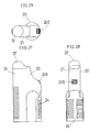
- Figs. 27 through 32 show a portable chiller as a seventh embodiment of the invention. wherein -
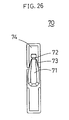
- this eyedrop container 70 which will be referred to in the following detailed description of the preferred embodiments, is described in some detail.
- this eyedrop container-dispenser 70 comprises a container 71 which is a rectangular plastic strip locally bulged out to form a housing in which an ophthalmic solution in a quantity equivalent to a single instillation dose is hermetically contained.
- a container 71 which is a rectangular plastic strip locally bulged out to form a housing in which an ophthalmic solution in a quantity equivalent to a single instillation dose is hermetically contained.
- an incision 73 On either side of the housing 71 and close to its neck portion 72 is an incision 73 so that in using the eyedrop a tear-off portion 74 is held and torn off along said incision 73 to expose the neck 72.
- the housing 71 is pressed with fingers to drip the ophthalmic solution from the neck 72. After instillation, the whole container is discarded.
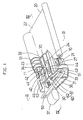
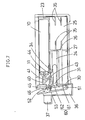
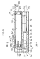
- Fig. 1 is a partially exploded overall perspective view
- Fig. 2 is an overall perspective view
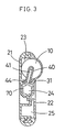
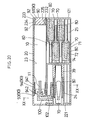
- Fig. 3 is a sectional view along the line III-III of Fig. 1
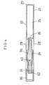
- Fig. 4 is a sectional view along the line IV-IV of Fig. 1
- Figs. 5 through 7 are sectional views showing the action of the embodiment.
- This portable chiller generally comprises a refrigerant cylinder 10 and a chiller case 20.
- the cylinder 10 contains a refrigerant which has been compressed into a liquid.
- the refrigerant may be any of nontoxic substances commonly employed for this kind of refrigeration, such as a fluorocarbon (Freon®, dupont), carbon dioxide, methyl chloride, butane and so on.
- a fluorocarbon Fluorocarbon
- a nozzle 11 To the forward end of this cylinder 10 is affixed a nozzle 11 in such a manner that as the nozzle 11 is forced into the cylinder 10, said refrigerant within the cylinder 10 is ejected via the nozzle 11.
- the chiller case 20 may be made of synthetic resin or metal, e.g. aluminum, and comprises a case body 21 and a cover 22.
- the case body 21 is formed, along one side thereof, with a cylinder compartment 23 for accepting the cylinder 10 and, alongside this cylinder compartment 23, a cooling compartment 24 and a compartment 25 for housing an article to be chilled are disposed in juxtaposition through a partitioning wall 26.
- a compartment 27 for housing additional articles to be chilled are further disposed on the opposite side of the cooling compartment 24 with respect to the cylinder compartment 23.
- the back of this case body 21 is provided with a plurality of ribs 28 for ensuring a cooling effect in the position corresponding to the cooling compartment 24.
- the aforesaid cover 22 releasably closes said cylinder compartment 23, cooling compartment 24 and compartments 25, 27 for housing articles to be chilled.
- This cover 22 is swingably supported by a hinge (not shown) about an edge of the case body 21 which is closer to the cylinder compartment 23 and can be set in position on the case body 21 with an appropriate engaging means (not shown) disposed at its free end.
- the part of said cover 22 which corresponds to said cooling compartment 24 is configurated to be generally complementary with the top configuration of the eyedrop container 70 (the article to be chilled) so that, upon closing the cover 22, the cooling compartment 24 is shut off as shown in Figs. 3 and 4.
- the said part corresponding to the cooling compartment 24 is also externally provided with a plurality of ribs 29 for insuring a cooling effect just as in the case of the ribs located on the case body 21.
- the cooling compartment 24 is adapted to chill the eyedrop container 70 (the article to be chilled loaded therein) and, as illustrated in Figs. 3 and 4, this internal wall surface is configured to be generally complementary with the exterior contour of the eyedrop container 70. While this cooling compartment 24 is secluded hermetically as said cover 22 is set in position as mentioned above, it is so arranged that a clearance is formed between the internal wall surface (the inner surface of the cover 22 and the side and bottom surfaces of the cooling compartment 24) and the eyedrop container 70 on closing so that the refrigerant may circulate around the eyedrop container 70. Furthermore, a vent orifice 31 is formed in the wall of this cooling compartment 24 which lies opposite to said partitioning wall 26 (i.e. the side wall 30 of case body 21).
- This vent orifice 31 has an inner peripheral surface tapered toward the cooling compartment 24 so that it is smaller in sectional area on the side of the cooling compartment 24.
- a refrigerant inlet 33 is formed in a side wall 32 of this cooling compartment 24 which is closer to the cylinder compartment 23.
- This refrigerant inlet 33 is an opening elongated in the longitudinal direction of the cooling compartment 24 and is flared toward the cooling compartment 24.
- a recess 34 is formed in the wall around the open end of said refrigerant inlet 33 which is farther from the cooling compartment 24.
- the compartments 25, 27 are adapted to accommodate a plurality of spare (four in the illustrated embodiment) eyedrop containers 70.
- a plurality of spare (four in the illustrated embodiment) eyedrop containers 70 are provided in the compartment 25.
- two pairs of juxtaposed projections 35 which are adapted to retain the eyedrop container 70 in position.
- these compartments 25, 27 for housing articles to be chilled need not necessarily be formed integrally with the case body 21 as in this embodiment but it may be so arranged, for instance, that a magazine carrying a plurality of eyedrop containers is loaded into the case body 21.
- the chiller case 20 has an adapter 40 and a lever 50, which constitute a refrigerant ejection means.
- the adapter 40 is disposed slidable in the axial direction of the cylinder 10 in the depth of the cylinder compartment 23.
- This adapter 40 is designed to introduce the refrigerant from a nozzle 11 of the cylinder 10 in the cylinder compartment 23 into said cooling compartment 24 and has a refrigerant passageway 41 extending therethrough.
- the adapter 40 is configured generally in the shape of the letter L, with one end thereof forming a nozzle socket 42 enlargeable with the tip of said nozzle 11 of cylinder 10, while the other end forming a refrigerant ejector 43 adjoining to said cooling compartment 24.
- This refrigerant ejector 43 has a rectangular collar 44 around it and this collar 44 is slidably fitted into said recess 34 to obstruct said refrigerant inlet 33 so that the refrigerant will not leak from the cooling compartment 24 into the cylinder compartment 23.
- the lever 50 functions to actuate ejection of the refrigerant from the cylinder 10 accommodated in the cylinder compartment 23.
- This lever 50 is disposed inside of a cover 36 formed integrally with the case body 21 via said side wall 30 and its base end portion is pivotally attached to a pin 51 projection from the internal wall of the cover 36 in parallel with said side wall 30.
- the forward end portion of said lever 50 is connected to said connecting rod 45.
- This connection to the connecting rod 45 is effected, as shown in Fig. 5, by fitting a connecting pin 52 disposed on the underside of the forward end portion of the lever 50 loosely into an axially elongated slot 46 (Fig.
- a vent closure member 60 constituting a refrigerant gasification control means.
- This vent closure member 60 keeps closing the vent orifice 31 of said cooling compartment 24 during the period from immediately before the beginning of ejection of the refrigerant by the refrigerant ejection means to completion of the refrigerant ejection to thereby withhold gasification of the refrigerant for a while and, then, open the vent orifice 31 to allow gasification of the refrigerant.
- This vent closure member 60 comprises an arm 61 formed integrally with the base of said lever 50 and a sealing plug 62 disposed at the end of the arm 61.
- the arm 61 is made of an elastic material and is, therefore, flexible.
- the sealing plug 62 is either integral with the arm 61 or a discrete unit secured rigidly to the end of the arm 61. When it is a discrete unit secured to the arm 61, the plug 62 can conveniently be made of a resilient material, such as rubber, which is excellent in sealing effect.
- This sealing plug 62 is configured to be complementary with the vent orifice 31 having an internally tapered surface so that it may positively plug off the vent orifice 31.
- This vent closure means 60 is normally in a position leaving the vent orifice 31 open but as said lever 50 is depressed, the means 60 is pivotally displaced toward the vent orifice 31 to close the vent orifice 31 with its sealing plug 62.
- the cover 22 of the chiller case 20 is opened and the cylinder compartment 23 is loaded with the cylinder 10.
- the nozzle 11 of the cylinder 10 is fitted into the nozzle socket 42 of the adapter 40.
- one of the eyedrop containers 70 is taken out from the compartment 25 or 27 and set it in position within the cooling compartment 24.
- the cover 22 is replaced onto the case body 21, whereby the cooling compartment 24 is hermetically sealed off except at the vent orifice 31.
- the lever protective cap 37 is snapped up to expose the forward end of the lever 50.
- the arm 61 of the vent closure member 60 is pivotally displaced toward the side wall 30 of the case body 21 to ultimately bring the sealing plug 62 of the member 60 into the vent orifice 31 (Fig. 5).
- the connecting pin 52 of the lever 50 is shifted only within the elongated slot 46 of the connecting rod 45 so that the connecting rod 45 is not disturbed by the depression of the lever 50. In other words, ejection of the refrigerant does not begin as yet.
- the arm 61 of the vent closure member 60 is flexed and the connecting rod 45 is pressed by the connecting pin 52 of the lever 50 at its elongated slot 46 and displaced toward the cylinder 10, whereupon the adapter 40 also slides toward the cylinder 10.
- the nozzle 11 is pressed into the cylinder 10 and, as a consequence, the refrigerant in the cylinder 10 is ejected through the refrigerant passageway 41 within the adapter 40 into the cooling compartment 24 (as indicated by the arrowmarks in Fig. 6).
- the refrigerant As the refrigerant is ejected into the cooling compartment 24 closed hermetically in the described manner, a high pressure is established in the cooling compartment 24 and the compartment 24 is impregnated with the liquid refrigerant not yet gasified despite ejection. Thus, in the cooling compartment 24, the eyedrop container 70 is immersed in the liquid refrigerant.
- the lever 50 As the ejection stops, the lever 50 is released, whereupon the recovery force of the arm 61 and coil spring 53 causes the lever 50 to return to its initial position. As a consequence, the adapter 40 also returns to its original position and the sealing plug 62 is released from the vent orifice 31 of the cooling compartment 24. Since the hermetic seal of the cooling compartment 24 is thus broken, the liquid refrigerant in high-pressure condition in the cooling compartment 24 is instantly gasified as it deprives the eyedrop container 70 of heat and the resultant refrigerant gas is vented from the chiller case 20 through the vent orifice 31 (as indicated by the arrowmark in Fig. 7). In this manner the eyedrop container 70 as a whole is instantly chilled.
- the cover 22 After waiting till the time when the chilling of the eyedrop container 70 is completed, the cover 22 is opened and the chilled container 70 is taken out from the cooling compartment 24 for instillation.
- the invention may be embodied in such otherwise fitted into the vent orifice of the cooling compartment and after completion of the refrigerant ejection it is removed manually or otherwise.
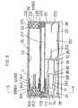
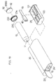
- Figs. 8 through 12 show another embodiment.
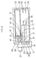
- Fig. 8 is a perspective view of the same with the case cover opened;
- Fig. 9 is a plan view in partial section;
- Fig. 10 is a sectional view taken along the line X-X of Fig. 9, with the cover closed;
- Fig. 11 is a right side elevation view, with the cover closed; and
- Fig. 12 is a front view of the same.
- This portable chiller generally comprises a cylinder 10, a chiller case 20 and a porous element 80.
- the construction of the cylinder 10 is similar to that of the first embodiment and, therefore, not described.
- the chiller case 20 which is also similar to that described for the first embodiment, is made of synthetic resin or metal, such as aluminum, and consists of a case body 21 and a cover 22.
- the case body 21 is formed, along its one side, with a cylinder compartment 23 for accepting said cylinder 10, and side-by-side with this cylinder compartment 23, a cooling compartment 24 and a compartment 25 for housing an article to be chilled are formed in juxtaposition as interrupted by a partitioning wall 26.
- This cylinder compartment 23 is provided with a refrigerant ejection means 90.
- the case body 21 is provided with a couple of cover stoppers 38, 38 toward both ends along the edge opposite to the edge along which said cylinder compartment 23 is disposed.
- the cylinder compartment 23 is open for accepting the cylinder 10 at its end closer to the compartment 25 as indicated by 231.
- the internal peripheral surface of this cylinder loading port 231 is formed with a female thread 232 and this port 231 is opened and closed with a cap 233 which is engageable with this female thread 232.
- This cap 233 is in the form of a short cylinder with its peripheral surface having a male thread 234 adapted to mesh with said female thread 232 and its inner peripheral surface being formed with a circumferentially extending annular stopper projection 235.
- Loosely fitted into this cap 233 is an ejection button 91 forming a part of said refrigerant ejection means 90 in such a manner that it can slide in the axial direction of the cap 233.
- This ejection button 91 is formed with stopper collars 92, 92 at both ends and as these stopper collars 92, 92 engage said stopper projection 235, this ejection button 91 is prevented from slipping out from the cap
- an adapter 100 Securely installed in the depth of the cylinder compartment 23 is an adapter 100, while a coil spring 93 and a socket 94 each constituting a part of said refrigerant ejection means 90 are disposed slidably in the axial direction of this compartment 23.
- the aforesaid adapter 100 functions to introduce the refrigerant from the nozzle 11 of the cylinder 10 set in the cylinder compartment 23 into said cooling compartment 24.
- This adapter 100 is formed, at its front side (the side facing the cylinder loading port 231), with a nozzle socket 101 for accepting the tip of the nozzle 11 of the cylinder 10 and internally with a refrigerant passageway 102 communicating with the nozzle socket 101 and cooling compartment 24.
- the aforesaid coil spring 93 and socket 94 are adapted to constantly preenergize the cylinder 10 in the cylinder compartment 23 toward the ejection button 91 in the cylinder loading port 231.
- the coil Spring 93 is biased between said adapter 100 and socket 94.
- the socket 94 consists of a large-diameter portion 941 bearing the forward end portion of the cylinder 10 and a smaller diameter portion 942 which is inserted into the coil spring 93.
- the aforesaid cooling compartment 24 is a chamber in which a single eyedrop container 70 (the article to be chilled) is set in position and chilled and its length is approximately equal to that of the eyedrop container 70. Also disposed is a half member 391 constituting a holding frame 39 for retaining the eyedrop container 70 fixedly in position. This half member 391 is formed, on the top surface adjacent to said cylinder compartment 23, with a channel 111 constituting a part of a refrigerant line 110 communicating with the refrigerant passageway 102 of the adapter 100 in the cylinder compartment 23. Moreover, in an intermediate position of the half member 393, that is the position corresponding to the housing portion 71 of the eyedrop container 70, there is provided a porous element mount 393 and said channel 111 terminates in the center of this mount 393.
- the aforesaid compartment 25 is designed to accommodate a plurality of spare eyedrop containers 70.
- this compartment 25 is divided into two chambers upper and lower, by a removable divider 251 so that a total of 4 containers 70, viz. 2 in the upper stage and 2 in the lower stage, can be accommodated.
- the divider 251 is formed with a pair of juxtaposed projections 252, 252 on each of its face and bottom sides, said each of projections extending from the center of the corresponding breadth of the divider, so that the eyedrop containers 70 accommodated on and under the divider 251 may be respectively held in position by said projections 252, 252.
- the aforesaid cover 22 is intended to open and close the above-described cooling compartment 24 and compartment 25 for housing the article to be chilled.
- This cover 22 is pivotally connected to the case body 21 by a hinge 201 located between the cylinder compartment 23 and the cooling compartment 24 and compartment 25. Attached to both free ends of this cover 22 are locks 381, 381 which are adapted to engage the cover engaging members 38, 38 of case body 21 and slidable in the longitudinal direction of the cover 22 but inseparable from the cover 22.
- this cover 22 is provided with a partitioning wall 261 in the position corresponding to the partitioning wall 26 between the cooling compartment 24 and compartment 25 of the case body 21 and a half member 392 constituting a part of said holding frame 39 in the position corresponding to the cooling compartment 24.
- this half member 392 is formed with a channel 112 constituting the counterpart of said refrigerant line 110 on the side adjoining said hinge 201, that is to say the side facing the cooling compartment 24.
- a porous element mount 394 is disposed in an intermediate position of this half member 392, that is to say the position corresponding to the housing portion 71 of the eyedrop container 70 and said channel 112 terminates in the central part of this porous element mount 394.
- the aforesaid porous element 80 serves to enclose the eyedrop container 70 set in the cooling compartment 24 of the chiller case 20 and absorbs the refrigerant ejected from the cylinder 10 in liquid form to assure a uniform gasification of the refrigerant around the eyedrop container 70.
- the material of such porous element 80 may be mentioned sponge, nonwoven fabric, paper, a synthetic rubber or urethane resin formed with a multiplicity of fine air cells.
- sponge is most advantageous in that it is not degraded at low temperature, this property being important because the temperature drops to near 0 °C, is well penetrable by the refrigerant (liquid) and has a large air-entrapping capacity.
- the pores in this porous element 80 may be open at both ends or at one end only.
- Such porous element 80 is used as half members 81 and 82, one of which is attached to the porous element mount 393 of the case body 21 adjacent to its cooling compartment 24 and the other to the porous element mount 394 of the cover 22, with an adhesive or an adhesive tape.
- the cap 233 is disconnected from the cylinder loading port 231 of the case body 21 to open the cylinder loading port 231.
- the cylinder 10 containing the refrigerant is loaded, with its nozzle 11 forward, into the cylinder compartment 23 through said cylinder loading port 231 and the cap 233 is replaced by threading it onto the cylinder loading port 231.
- the tip of the nozzle 11 of cylinder 10 is inserted into the nozzle socket 101 of the adapter 100, the tip of the cylinder 10 fits into the large-diameter portion 941 of the socket 94 and is subjected to the biasing force of the coil spring 93, whereupon the bottom surface of the cylinder 10 is pressed against the ejection button 91 within the cap 233 and the surface of the ejection button 91 becomes flush with the end face of the case body 21 and the surface of the cap 233.
- each of the locks 381, 381 of the case 20 is caused to slide outwardly to disengage the cover stoppers 38, 38 of the case body 21 and the cover 22 is opened.
- one eyedrop container 70 taken out from the compartment 25 is loaded into the cooling compartment 24 by setting it into the half members 391 of the holding frame 39.
- the cover 22 is replaced into the closed position and the locks 381, 381 are slid in the reverse directions into engagement with the cover engaging members 38, 38 of the case body 21.
- the eyedrop container 70 in the cooling compartment 24 is held in position by the holding frame 39 and the housing portion 71 of the container 70 as a whole is enshrouded by the porous element 80.
- the channels 111, 112 formed on the top (opposed) surfaces of the respective half-members 391, 392 are lined up to form said refrigerant line 110.
- the nozzle 11 is subjected to a reaction from the nozzle socket 101 of the adapter 100 and pushed into the cylinder 10, whereby the refrigerant is ejected from the cylinder 10 through the nozzle 11, the refrigerant passageway 102 within the adapter 100 and the refrigerant line 110 within the holding frame 39 to the porous element 80 within the cooling compartment 24.
- the ejected refrigerant is not instantly gasified because of the presence of the porous element 80 but absorbed in the liquid state into the porous element 80.
- the refrigerant absorbed into the porous element 80 diffuses into the whole body of the element 80 under the influence of ejection pressure and capillary phenomenon and deprives the porous element 80 and the air contained therein of heat. As a result, the whole porous element 80 is chilled and the housing portion 71 of the eyedrop container 70 which is enshrouded by the porous element 80 is also chilled from its entire surface.
- the locks 381, 381 of the chiller case 20 are disengaged, the cover 22 is opened, the chilled eyedrop container 70 is taken out, and the eyedrop is instilled.
- vent orifice 31 and the vent closure member 60 of the chiller case 20 are omitted and a porous element 80 is provided within a cooling compartment 24.
- the manner of use of this portable chiller is similar to that of the first embodiment. It should be understood that the elongated slot 46 of the connecting rod 45 is not essential and that the remainder of the construction is identical with that of the foregoing embodiment.
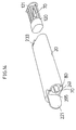
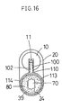
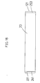
- Fig. 14 is a perspective view
- Fig. 15 is a transverse section view
- Fig. 16 is a sectional view taken along the line XVI-XVI of Fig. 15
- Fig. 17 is a right side elevation view
- Fig. 18 is a front view. It should be understood that, in these views, the like parts are indicated by the like numerals used for the preceding embodiments.
- openings 241, 253 of the cooling compartment 24 and the compartment 25 for housing articles to be chilled are disposed at respective ends of the chiller case 20, and the opening 241 of the cooling compartment 24 is releasably closed with a cover 221.
- the cooling compartment 24 is cylindrical and each of a holding frame 30 and a porous element 80 which are disposed therein is also a cylindrical member.
- the surface of the holding frame 30 which is facing said opening 241 is formed with a recess 395 so that the eyedrop container 70 may be easy to grip at its one end 74.
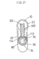
- the refrigerant line 110 within the holding frame 39 is bifurcated to insure a more efficient absorption of the refrigerant into the porous element 80 and the terminals of these branch lines 113, 114 are disposed in the positions facing the housing portion 71 of the eyedrop container 70.
- a magazine 120 Installed in the compartment 25 for housing spare articles to be chilled is a magazine 120 and a plurality of eyedrop containers 70 are first set in this magazine 120 and loaded into the compartment 25.
- four eyedrop containers 70 are accommodated in two rows and two stages.
- the bottom 121 of this magazine 120 doubles as a cover for opening and closing said opening 253.
- the cover 221 of the cooling compartment 24 is opened and an eyedrop container 70 is then inserted from its bottom end (the end opposite to the neck portion 72) into the cooling compartment 24 until a positive stop is felt. Then, the cover 221 is closed and the ejection button 91 is pressed to eject the refrigerant into the porous element 80.
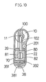
- Fig. 19 is a perpsective view
- Fig. 20 is a transverse section view
- Fig. 21 is a sectional view taken along the line XX-XX of Fig. 20
- Fig. 22 is a right side elevation view
- Fig. 23 is is front view. It should be understood that the like parts are indicated by the like numerals used for the preceding embodiments.
- the porous element 30 is formed as cylinder which can be sleeved over the housing portion 71 of the eyedrop container 70 and has been previously fitted on each eyedrop container 70. After chilling, it is removed and discarded.
- the porous element 80 is directly attached to the eyedrop container 70, the eyedrop container 70 carrying the porous element 80 is necessarily bulky but to compensate for this disadvantage, the magazine 120 loaded into the compartment 25 is divided ingeniously to permit efficient accommodation of eyedrop containers 70 and, hence, effective utilization of available space of the compartment 25.
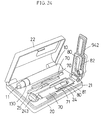
- Figs. 24 and 25 The sixth embodiment of the invention is illustrated in Figs. 24 and 25.
- Fig. 24 is an over all perspective view and
- Fig. 25 is a partial perspective view. It should be understood that the like parts are indicated by the like numerals used for the preceding embodiments.
- This embodiment is distinct in that the refrigerant is ejected from the cylinder 10 held in hand.
- the chiller case 20 comprises a case body 21 and a cover 22 for opening and closing it, and a cylinder compartment 130, a compartment 25 for housing spare art to be chilled, and a cooling compartment 24 are disposed in parallel on the top side of the case body 21.
- the cylinder compartment 130 and the compartment 25 for holding articles to be chilled are respectively formed as recesses complementary with the corresponding articles to be accommodated.
- the cooling compartment 24 is opened and closed with an inner cover 242 pivotally connected to the-top surface of the case body 21 and the cooling compartment 24 is completely sealed off as this inner cover 242 is closed.
- the inner cover 242 can be engaged or disengaged with respect to the case body 21 by turning a rotatable lock 243 disposed in an appropriate position on the top surface of the case body 21.
- the bottom surface of the cooling compartment 24 and the inner surface of the inner cover 242 are respectively formed with porous element mounts 393, 394 as in the second embodiment and half members 81, 82 constituting a porous element 80 are installed within these respective porous element bases 393, 394. Moreover, a nozzle socket 244 is disposed in an appropriate position of said inner cover 242.
- the cover 22 of the chiller case 20 is opened and the lock 243 is turned to release the inner cover 242 of the cooling compartment 24. Then, the inner cover 242 is opened and the eyedrop container 70 is taken out from the compartment 25 and loaded into the cooling compartment 24. There-after, the inner cover 242 is closed and the lock 243 is turned to engage the inner cover 242 with the case body 21.
- the cylinder 10 is taken out from the cylinder compartment 130 and its nozzle 11 is inserted into the nozzle socket 244 of the inner cover 242 and the body of the cylinder 10 is pressed toward the inner cover 242, whereupon the nozzle 11 is forced into the cylinder 10 and the refrigerant is accordingly ejected from the cylinder 10 into the porous element 80 within the cooling compartment 24 to chill the eyedrop container 70.
- the lock 243 is turned to release the inner cover 242, the inner cover 242 is then opened and the chilled eyedrop container 70 is taken out.
- Fig. 27 is a front view
- Fig. 28 is a left side elevation view
- Fig. 29 is a plan view
- Fig. 30 is a front view, with the protective cap 37 and cooling compartment 24 open
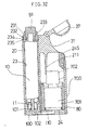
- Fig. 31 is a longitudinal section view showing the chiller in the condition of Fig. 30
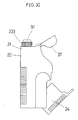
- Fig. 32 is a longitudinal section view showing the chiller loaded with the article 700 to be chilled in the cooling compartment 24.
- This embodiment is intended to be useful for situations where the article to be chilled is a smallsized bottle such as an ophthalmic drug bottle or a cosmetic bottle.
- This embodiment is distinct in that the whole cooling compartment is freely tiltable and the compartment for housing articles is omitted.
- an ejection button 91 is projecting from the top of the chiller case 20 and a protective cap 37 adapted to cover said projecting end is attached rotatably to the top end portion of the case body 21.
- the cooling compartment 24 is cup-shaped and is pivotally connected to the case body 21 in such a manner that it can tilt in and out about its lower end.
- This cooling compartment 24 has an inside diameter which is larger than the outer diameter of a barrel portion 701 of a bottle 700 to be chilled and a depth which is either equal to or slightly larger than said barrel 701.
- the inner peripheral surface of this cooling compartment 24 is thoroughly lined with a porous element 80.
- the thickness of this porous element 80 is slightly larger than the difference between the outer diameter of the barrel portion 701 of the bottle 700 and the inner diameter of the cooling compartment 24 so that when the cooling compartment 24 is loaded with the bottle 700, it closely contacts the peripheral surface of the barrel portion 701.
- a refrigerant passageway 110 disposed within the bottom wall of the cooling compartment 24 and a refrigerant passageway 102 within an adapter 100 disposed at the bottom of the cylinder compartment 23 are interconnected when the cooling compartment 24 as loaded into the case body 21.
- the reference numeral 211 indicates a bottle locking member disposed within the case body 21. As the cooling compartment 24 carrying the bottle 700 is installed within the case body 21, this bottle 700 is installed within the case body 21, this bottle locking member 211 abuts against the lateral side of a cap 702 on the bottle 700 to prevent rattling of the bottle 700 and rising thereof from the cooling compartment 24.
- the reference numeral 245 indicates a cooling compartment opening lever. As this lever 245 is pressed, the cooling compartment 24 is tilted out of the case body 21 to thereby open the cooling compartment 24.
- the cooling compartment opening lever 245 is pressed to open the cooling compartment 24 and after loading with the bottle 700 the cooling compartment 24 is pushed into the case body 21. As this is done, the cooling compartment opening lever 245 is reset in its original position.
- the protective cap 37 is opened to expose the ejection button 91, which is then depressed to deliver the refrigerant from the cylinder 10.
- the ejected refrigerant enters into the cooling compartment 24 through the refrigerant passageway 102 within the adapter 100 and the refrigerant passageway 110 on the side of the cooling compartment 24.
- the refrigerant As the refrigerant enters into the cooling compartment 24, a portion thereof is gasified but most of it retains its liquid form and flows through the clearance between the bottom surface of the cooling compartment 24 and the bottom surface of the bottle 700 into the porous element 80.
- the refrigerant absorbed into the porous element 80 diffuses throughout the porous element 80 under the pressure of ejection and by capillary action within the porous element 80 to remove heat from the porous element 80 and the air present therein. As a consequence, the whole porous element 80 is chilled and the barrel portion 701 of bottle 700 enshrouded by the porous element 80 is chilled from its entire peripheral surface.
- the cooling compartment 24 is opened by manipulating the cooling compartment opening lever 245 and the chilled bottle 700 is taken out for serving.
- the article to be chilled is an eyedrop container-dispenser, an eye drop bottle or a cosmetic bottle in the above embodiments, the article is not limited to these but may be a container containing any other drug, cosmetic or even a beverage.
- the shape and size of the portable chiller according to the present invention are chosen appropriately according to the kind of the article to be chilled.
Landscapes
- Health & Medical Sciences (AREA)
- Engineering & Computer Science (AREA)
- Veterinary Medicine (AREA)
- Life Sciences & Earth Sciences (AREA)
- Animal Behavior & Ethology (AREA)
- General Health & Medical Sciences (AREA)
- Public Health (AREA)
- Physics & Mathematics (AREA)
- Chemical & Material Sciences (AREA)
- Combustion & Propulsion (AREA)
- Mechanical Engineering (AREA)
- Thermal Sciences (AREA)
- General Engineering & Computer Science (AREA)
- Ophthalmology & Optometry (AREA)
- Pharmacology & Pharmacy (AREA)
- Biomedical Technology (AREA)
- Heart & Thoracic Surgery (AREA)
- Vascular Medicine (AREA)
- Hematology (AREA)
- Thermotherapy And Cooling Therapy Devices (AREA)
Claims (24)
- Tragbarer Kühler mit einem Zylinder (10), der ein verflüssigtes Gas-Kühlmittel und ein Ventil (11) enthält, welches das Kühlmittel von dem Zylinder (10) nur dann entläßt, wenn es in dem Zylinder (10) eingedrückt ist, sowie mit einem Kühlergehäuse (20), wobei das Kühlergehäuse (20) umfaßt:eine Zylinderabteilung (23), die den Zylinder (10) faßt, eine Kühlabteilung (24), in welche ein zu kühlender Artikel eingelegt und in welcher der Artikel gekühlt werden kann,Mittel (40,41), welche das Ventil (11) mit der Kühlabteilung (24) verbinden, undKühlmittel-Vergasungssteuermittel (45,50) mit einer Lüftungsöffnung (31), die in einer Wand (30) ausgeformt ist, welche die Kühlabteilung (24) begrenzt und die die Kühlabteilung (24) mit der Atmosphäre in Verbindung bringt,dadurch gekennzeichnet,
daß die Kühlmittel-Vergasungssteuermittel (45,50) weiterhin ein Lüftungsverschlußmittel (60) umfassen, welches dazu eingerichtet ist, die Lüftungsöffnung (31) in der Zeit unmittelbar vor Beginn der Ejektion bis zum Abschluß der Ejektion des Kühlmittels von dem Zylinder (10) in die Kühlabteilung (24) geschlossen zu halten, so daß die Vergasung des Kühlmittels unterbunden ist, und welches auch dazu eingerichtet ist, die Lüftungsöffnung (31) nach Abschluß der Ejektion zu öffnen, um die Vergasung des Kühlmittels in der Kühlabteilung (24) zu erlauben. - Tragbarer Kühler nach Anspruch 1, bei dem das Lüftungsverschlußmittel (60) mit den Verbindungsmitteln (40,41) und dem Ventil (11) in Wirkverbindung steht.
- Tragbarer Kühler nach Anspruch 2, bei dem das Lüftungsverschlußmittel (60) aus einem schwenkbaren Arm (61) mit einem Verschlußstopfen (62) zum lösbaren Verschluß der Lüftungsöffnung (62) besteht und das Verbindungsmittel (40,41) einen Adapter (40) mit einem Ansatz (42) zur Aufnahme des Ventils (11) des Zylinders und einer Kühlmittelleitung (41), die mit der Kühlmittelabteilung in Verbindung steht und gleitbeweglich in dem Kühlergehäuse (20) untergebracht ist, sowie einen Hebel (50) umfaßt, der das Ventil in den Zylinder (10) preßt, wobei der Arm (61) und der Hebel (50) so miteinander in Verbindung stehen, daß der Arm (61) dem Hebel (50) bei Betätigung folgt.
- Tragbarer Kühler nach Anspruch 3, bei dem der Arm (61) aus flexiblem Material hergestellt ist.
- Tragbarer Kühler nach Anspruch 3, wobei das Kühlergehäuse (20) weiterhin einen Mantel (36) hat, welcher den Hebel (50) und den Arm (61) einschließt und mit einer Schutzkappe (37) versehen ist, welche ein Betätigungsende des Hebels (50) wahlweise abdeckt oder freilegt.
- Tragbarer Kühler nach Anspruch 1, bei dem das Lüftungsverschlußmittel (60) ein Verschlußstopfen (62) ist, der in die Lüftungsöffnung (31) paßt.
- Tragbarer Kühler nach Anspruch 1 oder 5, bei dem das Kühlergehäuse (20) eine Abteilung (25,27) zum Fassen von einem oder mehreren zu kühlenden Ersatzartikeln (70) hat.
- Tragbarer Kühler nach Anspruch 7, bei dem die Abteilung (25,27) für Ersatzartikel ein Magazin umfaßt und eine Vielzahl von zu kühlenden Artikeln in die Abteilung (25,27) eingelegt sind, wie sie zuvor in das Magazin eingesetzt wurden.
- Tragbahrer Kühler mit einem Zylinder (10), der ein verflüssigtes Gas-Kühlmittel und ein Ventil (11) enthält, welches das Kühlmittel von dem Zylinder (10) nur dann entläßt, wenn es in den Zylinder (10) eingedrückt ist, sowie mit einem Kühlergehäuse (20), wobei das Kühlergehäuse (20) umfaßt:eine Zylinderabteilung (23), die den Zylinder (10) faßt, eine Kühlabteilung (24), in welche ein zu kühlender Artikel eingelegt und in welcher der Artikel gekühlt werden kann,Mittel (100,102,110,111,112), welche das Ventil (11) mit der Kühlabteilung (24) verbinden, undKühlmittel-Vergasungssteuermittel,dadurch gekennzeichnet,
daß die Kühlmittel-Vergasungssteuermittel ein poröses Element (80) umfassen, welches in der Kühlabteilung angeordnet ist und daran angepaßt ist, einen zu kühlenden Artikel in der Kühlabteilung (24) einzuhüllen und daran angepaßt ist, das Kühlmittel, welches von dem Zylinder (10) abgegeben ist, in flüssiger Form zu absorbieren und das Kühlmittel dann vergasen zu lassen. - Tragbarer Kühler nach Anspruch 9, bei dem das poröse Element (80) aus Schwamm hergestellt ist.
- Tragbarer Kühler nach Anspruch 9, bei dem das poröse Element (80) aus nicht-gewebten Stoff hergestellt ist.
- Tragbarer Kühler nach Anspruch 9, bei dem das poröse Element (80) aus Papier hergestellt ist.
- Tragbarer Kühler nach Anspruch 9, bei dem das poröse Element (80) aus synthetischem Gummi hergestellt ist, welches eine Vielzahl von Luftzellen enthält.
- Tragbarer Kühler nach Anspruch 9, bei dem das poröse Element (80) aus Urethan-Kunststoff hergestellt ist, welcher eine Vielzahl von Luftzellen enthält.
- Tragbarer Kühler nach Anspruch 9, bei dem das poröse Element (80) an der Kühlabteilung (24) angebracht ist.
- Tragbarer Kühler nach Anspruch 9, bei dem das poröse Element (80) daran angepaßt ist, um den zu kühlenden Artikel angelegt zu werden, bevor der Artikel in die Kühlabteilung (24) eingebracht wird, und von dem Artikel nach Kühlung entfernt zu werden.
- Tragbarer Kühler nach Anspruch 9, bei dem die Verbindungsmittel (100,102,110,111,112) umfassen:einen Adapter (100) mit einem Ansatzabschnitt (101) zum Aufnehmen des Ventils (11) des Zylinders (10) und einer Kühlmittelleitung (102), die mit der Kühlabteilung (24) in Verbindung steht und fest in der Tiefe der Zylinderabteilung (23) installiert ist,einen Ejektionsknopf (91), der schiebbar und demontierbar an der Zylinderabteilung (23) in einer solchen Weise angebracht ist, daß er sich gegen den Boden des Zylinderkörpers des Zylinders (10) in der Zylinderabteilung (23) abstützen kann, undVorspannungsmittel (93) zum konstanten Vorspannen des Zylinderkörpers des Zylinders (10) in der Zylinderabteilung (23) gegen den Ejektionsknopf (91).
- Tragbarer Kühler nach Anspruch 17, bei dem das Kühlergehäuse (20) eine Schutzkappe (233) zum Schützen des Ejektionsknopfs (91) aufweist, die geöffnet und geschlossen werden kann.
- Tragbarer Kühler nach Anspruch 18, bei dem das Kühlergehäuse (20) eine Abteilung (25) zur Aufnahme eines oder mehrerer zu kühlender Ersatzartikel (70) aufweist.
- Tragbarer Kühler nach Anspruch 19, bei dem die Abteilung zum Aufnehmen der zu kühlenden Ersatzartikel (70) mit einem Magazin (120) gefüllt werden kann und eine Vielzahl der Ersatzartikel in die Abteilung (25) gefüllt sind, wie sie zuvor in dem Magazin (120) eingesetzt wurden.
- Tragbarer Kühler nach Anspruch 9, bei dem das Kühlergehäuse (20) einen Ventilansatz (101) zum Aufnehmen des Ventils (11) des Zylinders (10) aufweist, um das Ventil (11) des Zylinders, welches aus der Zylinderabteilung (23) in dem Kühlergehäuse herausgenommen ist, aufzunehmen, und welches daran angepaßt ist, einen zu kühlenden Artikel (70,71) aufzunehmen, um diesen zu kühlen.
- Tragbarer Kühler nach Anspruch 21, bei dem das Kühlergehäuse (20) eine Abteilung (25) zum Aufnehmen eines oder mehrerer zu kühlender Ersatzartikel (70,71) aufweist.
- Tragbarer Kühler nach Anspruch 22, bei dem die Abteilung (25) zum Aufnehmen von Ersatzartikeln (70,71) mit einem Magazin gefüllt werden kann und eine Vielzahl der zu kühlenden Artikel in diese Abteilung (25) gefüllt sind, wie sie zuvor in das Magazin eingesetzt wurden.
- Tragbarer Kühler nach einem der Ansprüche 1, 5, 7, 21, 23, bei dem das Kühlergehäuse (20) eine Vielzahl von Rippen (35) zum Kühlen in einer Position aufweist, welche der Kühlabteilung (24) entspricht.
Applications Claiming Priority (4)
| Application Number | Priority Date | Filing Date | Title |
|---|---|---|---|
| JP14504690A JPH0439583A (ja) | 1990-06-01 | 1990-06-01 | 携帯用冷却器 |
| JP145046/90 | 1990-06-01 | ||
| JP15671490A JPH063336B2 (ja) | 1990-06-14 | 1990-06-14 | 携帯用冷却器 |
| JP156714/90 | 1990-06-14 |
Publications (3)
| Publication Number | Publication Date |
|---|---|
| EP0459508A2 EP0459508A2 (de) | 1991-12-04 |
| EP0459508A3 EP0459508A3 (en) | 1992-06-03 |
| EP0459508B1 true EP0459508B1 (de) | 1996-12-04 |
Family
ID=26476298
Family Applications (1)
| Application Number | Title | Priority Date | Filing Date |
|---|---|---|---|
| EP91108934A Expired - Lifetime EP0459508B1 (de) | 1990-06-01 | 1991-05-31 | Tragbarer Kühler |
Country Status (6)
| Country | Link |
|---|---|
| US (2) | US5189890A (de) |
| EP (1) | EP0459508B1 (de) |
| KR (1) | KR920001158A (de) |
| CA (1) | CA2043303C (de) |
| DE (1) | DE69123389T2 (de) |
| ES (1) | ES2098281T3 (de) |
Families Citing this family (22)
| Publication number | Priority date | Publication date | Assignee | Title |
|---|---|---|---|---|
| US6230501B1 (en) | 1994-04-14 | 2001-05-15 | Promxd Technology, Inc. | Ergonomic systems and methods providing intelligent adaptive surfaces and temperature control |
| USD376156S (en) | 1995-07-12 | 1996-12-03 | Stevenson Robert L | Manual refrigeration apparatus |
| IT1312097B1 (it) * | 1999-04-23 | 2002-04-04 | Istituto Profilattico Italiano | Procedimento per l'applicazione di prodotti cosmetici a temperaturacontrollata inferiore alla temperatura ambiente. |
| US7219449B1 (en) | 1999-05-03 | 2007-05-22 | Promdx Technology, Inc. | Adaptively controlled footwear |
| KR20020023834A (ko) * | 2001-09-26 | 2002-03-29 | 박선우 | 직접 삽입식 냉각방법 및 냉각장치 |
| US7423779B2 (en) * | 2004-03-30 | 2008-09-09 | Omnivision Technologies, Inc. | Method and apparatus for automatic white balance |
| FR2890160B1 (fr) * | 2005-09-01 | 2010-04-02 | Oreal | Dispositif de refroidissement et ensemble le comportant pour le refroidissement d'un dispositif de conditionnement d'un produit,notamment cosmetique |
| FR2894163B1 (fr) * | 2005-12-07 | 2008-02-22 | Oreal | Dispositif de refroidissement d'un produit et ensemble de conditionnement et de distribution d'un produit |
| FR2900317B1 (fr) * | 2006-04-28 | 2008-07-18 | Oreal | Boitier et procede pour refroidir un produit cosmetique ou de soin, kit cosmetique comprenant un tel boitier et utilisation d'un tel kit |
| FR2902773B1 (fr) * | 2006-06-22 | 2011-05-20 | Oreal | Ensemble de conditionnement et de distribution refrigeree d'un produit |
| USD598739S1 (en) | 2008-03-14 | 2009-08-25 | Denise London | Container |
| ES2510290B2 (es) | 2013-03-20 | 2015-04-30 | Emilio PALOMO PINTO | Sistema de refrigeración autónomo, portátil y autorefrigerante, basado en la utilización de un depósito estanco, conteniente de un gas licuado a presión, empleado como vaporizador, como consecuencia de la evaporación controlada de dicho GLP |
| CN104061729B (zh) * | 2014-06-28 | 2017-08-29 | 江西际海制冷设备有限公司 | 一种动力源外接压缩储冷便携式无电源制冷装置 |
| US10729600B2 (en) | 2015-06-30 | 2020-08-04 | The Procter & Gamble Company | Absorbent structure |
| WO2017079601A1 (en) | 2015-11-04 | 2017-05-11 | The Procter & Gamble Company | Absorbent structure |
| CA3004313A1 (en) | 2015-11-04 | 2017-05-11 | The Procter & Gamble Company | Absorbent structure |
| US11173078B2 (en) | 2015-11-04 | 2021-11-16 | The Procter & Gamble Company | Absorbent structure |
| US20180318151A1 (en) | 2017-05-03 | 2018-11-08 | The Procter & Gamble Company | Absorbent article having multiple zones |
| WO2019090293A1 (en) | 2017-11-06 | 2019-05-09 | The Procter & Gamble Company | Absorbent article with conforming features |
| CN111601576B (zh) | 2017-11-06 | 2022-11-25 | 宝洁公司 | 具有节点和支柱的结构 |
| US10722427B2 (en) * | 2018-03-29 | 2020-07-28 | Simon Charles Cantor | Hermetically sealable case for medical device and medicine |
| EP4063294A4 (de) * | 2019-12-27 | 2023-08-30 | Mdap Co., Ltd. | Vorrichtung zur verankerung einer probensendung zur verwendung in einem vakuumisolierten doppelwandigen behälter |
Family Cites Families (10)
| Publication number | Priority date | Publication date | Assignee | Title |
|---|---|---|---|---|
| US2775872A (en) * | 1955-10-11 | 1957-01-01 | Bell George Clarence | Absorbent jacket for pail and pail having absorbent jacket |
| US2805556A (en) * | 1955-11-22 | 1957-09-10 | Wang Wensan | Pocket liquid cooling device |
| US2900808A (en) * | 1955-11-22 | 1959-08-25 | Wang Wensan | Pocket liquid cooling device |
| GB1150652A (en) * | 1965-05-13 | 1969-04-30 | Angelo Bottani | Refrigerating Apparatus |
| US3302425A (en) * | 1965-11-24 | 1967-02-07 | Lois M Morrison | Frozen food container |
| US3529437A (en) * | 1968-08-05 | 1970-09-22 | Edward J Bell | Self-cooling drinking fountain |
| US4054037A (en) * | 1975-07-09 | 1977-10-18 | Paul C. Rhyne, Jr. | Portable apparatus for sequentiallly cooling a plurality of containers of beverages and the like |
| GB2070434B (en) * | 1980-03-04 | 1984-02-29 | Vyzk Ustav Silnoproude Elekt | Cryogenic apparatus for surgery |
| KR870001631Y1 (ko) * | 1984-07-10 | 1987-04-30 | 김호 | 캔의 자체 냉각장치 |
| US4640101A (en) * | 1985-12-18 | 1987-02-03 | Johnson Ken A | Portable beverage chiller |
-
1991
- 1991-05-27 CA CA002043303A patent/CA2043303C/en not_active Expired - Fee Related
- 1991-05-30 KR KR1019910008918A patent/KR920001158A/ko not_active Abandoned
- 1991-05-31 ES ES91108934T patent/ES2098281T3/es not_active Expired - Lifetime
- 1991-05-31 DE DE69123389T patent/DE69123389T2/de not_active Expired - Fee Related
- 1991-05-31 EP EP91108934A patent/EP0459508B1/de not_active Expired - Lifetime
-
1992
- 1992-07-17 US US07/914,656 patent/US5189890A/en not_active Expired - Fee Related
- 1992-12-07 US US07/986,519 patent/US5287707A/en not_active Expired - Fee Related
Also Published As
| Publication number | Publication date |
|---|---|
| DE69123389T2 (de) | 1997-06-26 |
| US5189890A (en) | 1993-03-02 |
| EP0459508A3 (en) | 1992-06-03 |
| ES2098281T3 (es) | 1997-05-01 |
| DE69123389D1 (de) | 1997-01-16 |
| EP0459508A2 (de) | 1991-12-04 |
| KR920001158A (ko) | 1992-01-30 |
| US5287707A (en) | 1994-02-22 |
| CA2043303C (en) | 1996-09-03 |
| CA2043303A1 (en) | 1991-12-02 |
Similar Documents
| Publication | Publication Date | Title |
|---|---|---|
| EP0459508B1 (de) | Tragbarer Kühler | |
| US5842682A (en) | Non-leaking, non-venting liquid filled canister quick disconnect system | |
| EP1306314B1 (de) | Verschluss und Doppelbehälter | |
| US5115940A (en) | Container cooler apparatus | |
| US20080067194A1 (en) | Container for Packaging a Liquid to be Dispensed in Drops, Reversibly Deformed by Air Input | |
| US4775081A (en) | Device for the actuator of a valve fitted on a pressurized container | |
| CN104070821A (zh) | 液体盒 | |
| WO2000068648A3 (en) | A valved dispensing system with priming liquid loss prevention | |
| CN101945617A (zh) | 用于存储冷冻手术设备的容器 | |
| HU225344B1 (en) | Container with pressure control device for dispensing fluid, pressure control device and method for manufacturing the container | |
| JP6670671B2 (ja) | 吐出器 | |
| WO1996024553A1 (en) | Soda bottle cap | |
| US20100162734A1 (en) | Self-Chilling Container | |
| JP6262997B2 (ja) | 圧縮ガスのレギュレータと該レギュレータを備えた炭酸ミスト美顔器 | |
| JPH0632859Y2 (ja) | 容器内化成ガス利用噴射装置 | |
| KR20090002434U (ko) | 화장품 용기 | |
| JPH10337523A (ja) | ペンタイプの瞬間接着剤容器 | |
| KR200166217Y1 (ko) | 캔용 냉각장치 | |
| JPH0448176A (ja) | 携帯用冷却器 | |
| JPH0439583A (ja) | 携帯用冷却器 | |
| KR0133211B1 (ko) | 냉각장치 | |
| GB2201146A (en) | Removing bottle stopper | |
| US20250178353A1 (en) | Liquid storage container | |
| JPH02218462A (ja) | エアゾール容器 | |
| JPS6231142Y2 (de) |
Legal Events
| Date | Code | Title | Description |
|---|---|---|---|
| PUAI | Public reference made under article 153(3) epc to a published international application that has entered the european phase |
Free format text: ORIGINAL CODE: 0009012 |
|
| AK | Designated contracting states |
Kind code of ref document: A2 Designated state(s): CH DE ES FR GB IT LI NL |
|
| PUAL | Search report despatched |
Free format text: ORIGINAL CODE: 0009013 |
|
| AK | Designated contracting states |
Kind code of ref document: A3 Designated state(s): CH DE ES FR GB IT LI NL |
|
| 17P | Request for examination filed |
Effective date: 19921202 |
|
| 17Q | First examination report despatched |
Effective date: 19940307 |
|
| GRAG | Despatch of communication of intention to grant |
Free format text: ORIGINAL CODE: EPIDOS AGRA |
|
| GRAH | Despatch of communication of intention to grant a patent |
Free format text: ORIGINAL CODE: EPIDOS IGRA |
|
| GRAH | Despatch of communication of intention to grant a patent |
Free format text: ORIGINAL CODE: EPIDOS IGRA |
|
| GRAA | (expected) grant |
Free format text: ORIGINAL CODE: 0009210 |
|
| AK | Designated contracting states |
Kind code of ref document: B1 Designated state(s): CH DE ES FR GB IT LI NL |
|
| REF | Corresponds to: |
Ref document number: 69123389 Country of ref document: DE Date of ref document: 19970116 |
|
| ITF | It: translation for a ep patent filed | ||
| PGFP | Annual fee paid to national office [announced via postgrant information from national office to epo] |
Ref country code: GB Payment date: 19970421 Year of fee payment: 7 |
|
| EN | Fr: translation not filed | ||
| REG | Reference to a national code |
Ref country code: CH Ref legal event code: NV Representative=s name: ISLER & PEDRAZZINI AG |
|
| REG | Reference to a national code |
Ref country code: ES Ref legal event code: FG2A Ref document number: 2098281 Country of ref document: ES Kind code of ref document: T3 |
|
| PGFP | Annual fee paid to national office [announced via postgrant information from national office to epo] |
Ref country code: ES Payment date: 19970514 Year of fee payment: 7 |
|
| PGFP | Annual fee paid to national office [announced via postgrant information from national office to epo] |
Ref country code: CH Payment date: 19970526 Year of fee payment: 7 |
|
| PGFP | Annual fee paid to national office [announced via postgrant information from national office to epo] |
Ref country code: NL Payment date: 19970531 Year of fee payment: 7 |
|
| REG | Reference to a national code |
Ref country code: GB Ref legal event code: 711B |
|
| PGFP | Annual fee paid to national office [announced via postgrant information from national office to epo] |
Ref country code: DE Payment date: 19970610 Year of fee payment: 7 |
|
| REG | Reference to a national code |
Ref country code: FR Ref legal event code: FC Ref country code: FR Ref legal event code: RN |
|
| ET | Fr: translation filed | ||
| PLBE | No opposition filed within time limit |
Free format text: ORIGINAL CODE: 0009261 |
|
| STAA | Information on the status of an ep patent application or granted ep patent |
Free format text: STATUS: NO OPPOSITION FILED WITHIN TIME LIMIT |
|
| 26N | No opposition filed | ||
| REG | Reference to a national code |
Ref country code: GB Ref legal event code: 711H |
|
| PG25 | Lapsed in a contracting state [announced via postgrant information from national office to epo] |
Ref country code: CH Free format text: LAPSE BECAUSE OF NON-PAYMENT OF DUE FEES Effective date: 19980531 Ref country code: LI Free format text: LAPSE BECAUSE OF NON-PAYMENT OF DUE FEES Effective date: 19980531 Ref country code: GB Free format text: LAPSE BECAUSE OF NON-PAYMENT OF DUE FEES Effective date: 19980531 |
|
| PG25 | Lapsed in a contracting state [announced via postgrant information from national office to epo] |
Ref country code: ES Free format text: LAPSE BECAUSE OF NON-PAYMENT OF DUE FEES Effective date: 19980601 |
|
| PG25 | Lapsed in a contracting state [announced via postgrant information from national office to epo] |
Ref country code: NL Free format text: LAPSE BECAUSE OF NON-PAYMENT OF DUE FEES Effective date: 19981201 |
|
| PG25 | Lapsed in a contracting state [announced via postgrant information from national office to epo] |
Ref country code: FR Free format text: LAPSE BECAUSE OF NON-PAYMENT OF DUE FEES Effective date: 19981231 |
|
| REG | Reference to a national code |
Ref country code: CH Ref legal event code: PL |
|
| GBPC | Gb: european patent ceased through non-payment of renewal fee |
Effective date: 19980531 |
|
| NLV4 | Nl: lapsed or anulled due to non-payment of the annual fee |
Effective date: 19981201 |
|
| PG25 | Lapsed in a contracting state [announced via postgrant information from national office to epo] |
Ref country code: DE Free format text: LAPSE BECAUSE OF NON-PAYMENT OF DUE FEES Effective date: 19990302 |
|
| REG | Reference to a national code |
Ref country code: FR Ref legal event code: ST |
|
| REG | Reference to a national code |
Ref country code: ES Ref legal event code: FD2A Effective date: 20000503 |
|
| PG25 | Lapsed in a contracting state [announced via postgrant information from national office to epo] |
Ref country code: IT Free format text: LAPSE BECAUSE OF NON-PAYMENT OF DUE FEES;WARNING: LAPSES OF ITALIAN PATENTS WITH EFFECTIVE DATE BEFORE 2007 MAY HAVE OCCURRED AT ANY TIME BEFORE 2007. THE CORRECT EFFECTIVE DATE MAY BE DIFFERENT FROM THE ONE RECORDED. Effective date: 20050531 |
|
| PG25 | Lapsed in a contracting state [announced via postgrant information from national office to epo] |
Ref country code: FR Free format text: LAPSE BECAUSE OF NON-PAYMENT OF DUE FEES Effective date: 19970531 |