EP0458366A2 - Dispositif pour la manipulation de seringues - Google Patents
Dispositif pour la manipulation de seringues Download PDFInfo
- Publication number
- EP0458366A2 EP0458366A2 EP91108530A EP91108530A EP0458366A2 EP 0458366 A2 EP0458366 A2 EP 0458366A2 EP 91108530 A EP91108530 A EP 91108530A EP 91108530 A EP91108530 A EP 91108530A EP 0458366 A2 EP0458366 A2 EP 0458366A2
- Authority
- EP
- European Patent Office
- Prior art keywords
- syringe
- syringes
- detection
- unit
- elements
- Prior art date
- Legal status (The legal status is an assumption and is not a legal conclusion. Google has not performed a legal analysis and makes no representation as to the accuracy of the status listed.)
- Withdrawn
Links
Images
Classifications
-
- G—PHYSICS
- G07—CHECKING-DEVICES
- G07F—COIN-FREED OR LIKE APPARATUS
- G07F7/00—Mechanisms actuated by objects other than coins to free or to actuate vending, hiring, coin or paper currency dispensing or refunding apparatus
- G07F7/06—Mechanisms actuated by objects other than coins to free or to actuate vending, hiring, coin or paper currency dispensing or refunding apparatus by returnable containers, i.e. reverse vending systems in which a user is rewarded for returning a container that serves as a token of value, e.g. bottles
-
- A—HUMAN NECESSITIES
- A61—MEDICAL OR VETERINARY SCIENCE; HYGIENE
- A61M—DEVICES FOR INTRODUCING MEDIA INTO, OR ONTO, THE BODY; DEVICES FOR TRANSDUCING BODY MEDIA OR FOR TAKING MEDIA FROM THE BODY; DEVICES FOR PRODUCING OR ENDING SLEEP OR STUPOR
- A61M5/00—Devices for bringing media into the body in a subcutaneous, intra-vascular or intramuscular way; Accessories therefor, e.g. filling or cleaning devices, arm-rests
- A61M5/178—Syringes
- A61M5/31—Details
- A61M5/32—Needles; Details of needles pertaining to their connection with syringe or hub; Accessories for bringing the needle into, or holding the needle on, the body; Devices for protection of needles
- A61M5/3205—Apparatus for removing or disposing of used needles or syringes, e.g. containers; Means for protection against accidental injuries from used needles
Definitions
- the invention relates to a device for handling syringes and, in particular, to such a device which is capable of receiving used syringes, recognizing them as such and, after this recognition process, actuating a dispensing unit via which objects such as a coin or a new syringe are used be issued.
- the invention has for its object to provide a device for handling syringes, which is very simple in construction and at the same time is extremely reliable in order to recognize imported, used syringes as such and, if necessary, to deliver an object in exchange, for example a coin or a new one Syringe.
- a detection unit which has the following components: a tubular body for individually holding a syringe in a position which is essentially coaxial with the tubular body, detection elements for determining the presence of certain areas the syringe and for emitting a signal when the presence of the particular sections has been determined, and actuators which respond to the signal and in response actuate a dispensing unit which is coupled to the detection unit.
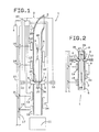
- Figures 1 and 2 show a device 1 for handling syringes with a detection unit 2 for used syringes 3 and a working unit which has a dispensing unit 4 which, after recognizing a used syringe 3 as such, dispenses an object, for example a new syringe or a coin.
- the detection unit 2 has an input nozzle 5 which is inclined to the vertical and through which the syringes 3 can be introduced one after the other.
- the inlet nozzle 5 leads at its lower end to a vertical tube 6, the diameter of which is larger than the diameter of the syringes 3 and the length of which essentially corresponds to twice the length of a syringe 3.
- the tube 6 In its central region, the tube 6 has two diametrically opposite openings 7, through which two holding elements 8, which are aligned and displaceable in the longitudinal direction, protrude.
- Each holding element 8 has a horizontal, substantially parallel flat finger 9, which is bevelled on its upper side in the region of the free end reaching into the tube 6.
- the end of the rod 9 lying outside the tube 6 is connected to an actuating element 10, by means of which the finger 9 can be adjusted transversely to the tube 6.
- the lower end of the tube 6 is open and is located above a collecting container 11 for syringes 3 which have passed through the detection unit 2.
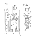
- two metal detection elements 14 and 15 are provided along the area of the tube 6 that lies under the fingers 9, at the level of an upper and a lower portion, respectively.
- the detection element 12 When the detection element 12 detects a metallic body, it emits an electrical signal, which closes a normally open switch 16 which is built into an electrical line 17 which is connected to the dispensing unit 4.
- the delivery unit 4 is connected to the recognition unit 2, which is preferably in accordance with Italian patent application 3521 A / 90 from May 25. 1990 trained.
- the dispensing unit 4 is designed such that, as already mentioned, it dispenses an object, for example a coin or a syringe, if the recognition unit 2 has given it approval for this.
- the detection unit 13 If the detection unit 13 does not detect a metallic body, it, by emitting an electrical signal, holds a switch 18 which is located in the electrical line 17 and which is opened by the detection unit 13 when there is a metallic object in its detection area.
- the detection element 15 When the detection element 15 detects a metallic body, it closes a normally open switch 19, which is located in an electrical line 20 which is connected in parallel to the electrical line 17, by emitting an electrical signal.
- the detection element 14 acts via an electrical signal on a switch 21 in the electrical line 20 in the same way as the detection element 13 on the switch 18.
- the electrical lines 17 and 20 are lines for transmitting approval signals for the activation of the delivery unit 4 and can coincide with the supply lines for this delivery unit 4.
- Said switches 16, 18, 19 and 21 are also referred to below as actuators, since the dispensing unit 4 is actuated via them and their paired closed state.
- a detection element 22 for determining the presence of an object in the embodiment of a syringe 3, is arranged along a central region of the tube 6 above the fingers 9, which element consists, for example, of an inductive sensor and is connected to a known timer 23.
- the timer 23 activates the detection elements 12, 13, 14 and 15 after a predetermined time, whereupon the actuators 10 are switched on after a certain time following the activation.
- a detection element 24 is provided below the fingers 9 next to a central region of the tube 6, which detects the presence of an object and is connected to the aforementioned time circuit 23, after a predetermined time following the detection of the presence of a syringe 3 to activate the detection elements 12, 13, 14 and 15.
- the pure and simple detection of the presence of an object by means of the detection elements 22 and 24 could be carried out by any device having the same effect, for example by a photocell 25, which is able to pass an object through an opening (not shown) in the tube 6 Determine tube 6 through.
- the used syringes 3 When using the device, the used syringes 3 have to be introduced into the detection unit 2 via the input nozzle 5. If the syringes 3 are inserted with the needle pointing backwards, the situation shown in FIG. 1 results, while FIG. 2 shows the case in which a syringe 3 is inserted with the needle ahead. While a syringe 3 is inserted into the detection unit 2, the actuating members 10 hold the fingers 9 in their advanced position, in which they partially engage in the tube 6 (see FIGS. 1 and 2).
- the syringe therefore rests on the fingers 9 with its two laterally projecting flange sections 26, the pressure end 27 of the plunger of the syringe being below the two fingers 9.
- the presence of the syringe 3 is determined by the detection element 22, which then activates the timer 23, which actuates the detection elements 12 and 13 after a predetermined time.
- the detection element 12 detects the presence of the needle 28 and thereby closes the switch 16, while the detection element 13 detects the Plastic area of the syringe 3, ie determines the absence of metallic parts, whereby the switch 18 is closed.
- the detection element 24 determines the presence of the syringe and activates the timer 23 in accordance with the processes already explained, which in turn activates the detection elements 14 and 15 after a predetermined time.
- the two detection elements 22 and 24 and the associated timer 23 prevent the detection unit 2 from being activated immediately when an object is inserted into the tube 6 that is not a syringe and cannot be held in the control position by the fingers 9 . Such an object immediately falls past the fingers 9 into the collecting container 11 before the timer 23 can activate the detection elements 12, 13, 14 and 15. If the detection elements 12, 13, 14 and 15 are activated and there is no longer any object in the tube 6, they can in no way start the delivery unit 4.
- the detection element 22 activates the timer 23, which activates the detection elements 12 and 13 after a certain time.
- the two detection elements 12 and 13 will normally never be able to close the switches 16 and 18 in pairs, so that the dispensing unit 4 is not actuated.
- the timer 23 activates the actuators 10, whereby the two fingers 9 are withdrawn and the object falls into the container 11.
- the detection unit 2 is thus able to work faultlessly regardless of the direction in which the syringe 3 is inserted into the tube 6, which represents an additional guarantee for the reliability of the detection unit 2.
- the detection elements 22 and 24 may be missing, while the detection elements 12, 13, 14 and 15 also serve as means for detecting the presence of objects in the tube 6, with the timer 23 and not are connected to switches 16, 18, 19 and 21.
- the switches 16, 18, 19 and 21 as well as the actuators 10 would be activated by the timer 23 in a manner similar to that already explained, after a time interval which is determined by the previously explained control operation which is carried out on the objects by the detection elements 12, 13, 14 and 15 has been made.
- the inner circumference of the cross section of the tube 6 has a shape, at least in the control zone in which the syringes 3 are to be recognized, which essentially corresponds to the shape of the outer circumference of an axial projection of a syringe 3 onto one plane reproduces.
- this control zone in the area of the two zones, which represent the outer shape of the two laterally projecting flange sections 26 of a syringe 3, are the corresponding sensors 29 of two microswitches 30, which are connected in series in a line 31 to Delivery of an electrical signal for the activation of the delivery unit 4.
- the laterally projecting flange sections 26 are located in the area of the sensors 29, as a result of which they are moved elastically downward and the microswitches 30 are closed, which results in the activation of the dispensing unit 4.
- the area of the tube 6 below the fingers 9 may be missing, the syringes 3 introduced in the position in FIG. 2 hanging freely downwards from the fingers 9 during the recognition operation, in order to follow the recognition operation in to drop the container 11.
- the holding elements 8 can be carried out in any suitable manner, provided that they are only able to hold the syringes 3 in the previously explained position during the recognition operation. It is also possible for the holding elements 8 to hold parts of the syringes 3 other than the laterally projecting flange sections 26, in which case the necessary changes to the detection unit 2 merely consist in arranging the detection elements 12, 13, 14 and 15 in a correspondingly different place.
- the detection elements 13 and 14 with the associated switches 18 and 21 may be missing.
- the function of the recognition unit 2 would be limited to checking an object inserted into the tube 6 to determine whether it has a metallic part, preferably the needle of a syringe, in a specific region of the tube 6, this specific part being shown in FIG Height should be at which the metallic part is normally arranged to ensure that the object is actually a syringe.
- the device 1 according to the invention fully achieves the goals set.
- this device has proven to be extremely reliable and yet very simple, so that the underlying problem is solved.
Landscapes
- Health & Medical Sciences (AREA)
- Engineering & Computer Science (AREA)
- Life Sciences & Earth Sciences (AREA)
- Animal Behavior & Ethology (AREA)
- Anesthesiology (AREA)
- Biomedical Technology (AREA)
- Heart & Thoracic Surgery (AREA)
- Hematology (AREA)
- Environmental & Geological Engineering (AREA)
- Vascular Medicine (AREA)
- General Health & Medical Sciences (AREA)
- Public Health (AREA)
- Veterinary Medicine (AREA)
- Physics & Mathematics (AREA)
- General Physics & Mathematics (AREA)
- Infusion, Injection, And Reservoir Apparatuses (AREA)
- External Artificial Organs (AREA)
Applications Claiming Priority (2)
| Application Number | Priority Date | Filing Date | Title |
|---|---|---|---|
| IT3522A IT1238963B (it) | 1990-05-25 | 1990-05-25 | Unita' per la manipolazione di siringhe. |
| IT352290 | 1990-05-25 |
Publications (2)
| Publication Number | Publication Date |
|---|---|
| EP0458366A2 true EP0458366A2 (fr) | 1991-11-27 |
| EP0458366A3 EP0458366A3 (en) | 1993-02-03 |
Family
ID=11108975
Family Applications (1)
| Application Number | Title | Priority Date | Filing Date |
|---|---|---|---|
| EP19910108530 Withdrawn EP0458366A3 (en) | 1990-05-25 | 1991-05-25 | Seringe processing apparatus |
Country Status (2)
| Country | Link |
|---|---|
| EP (1) | EP0458366A3 (fr) |
| IT (1) | IT1238963B (fr) |
Cited By (3)
| Publication number | Priority date | Publication date | Assignee | Title |
|---|---|---|---|---|
| EP0654003A4 (fr) * | 1992-08-14 | 1997-07-30 | Imaging Tech Pty Ltd | Appareil pour stocker et distribuer des articles. |
| FR2802516A1 (fr) * | 1999-12-20 | 2001-06-22 | M P Lab | Dispositif de collecte des seringues usagees et de distribution d'un avoir |
| US11458254B2 (en) * | 2015-05-13 | 2022-10-04 | Ypsomed Ag | Adjustable injection device |
Family Cites Families (5)
| Publication number | Priority date | Publication date | Assignee | Title |
|---|---|---|---|---|
| US3878967A (en) * | 1974-04-03 | 1975-04-22 | Sherwood Medical Ind Inc | Medicament dispenser |
| GB2182917B (en) * | 1985-11-15 | 1988-09-21 | Commw Ind Gases | Exchanging/vending machine for gas cylinders |
| GB8701230D0 (en) * | 1987-01-21 | 1987-02-25 | Burke N F P | Syringe disposal aid |
| NO881632L (no) * | 1988-04-15 | 1989-10-16 | Arne Veidung | Automat for enganssproeyte. |
| NL8900310A (nl) * | 1989-02-08 | 1990-09-03 | Univ Amsterdam | Inrichting voor het omruilen van injectiespuiten. |
-
1990
- 1990-05-25 IT IT3522A patent/IT1238963B/it active IP Right Grant
-
1991
- 1991-05-25 EP EP19910108530 patent/EP0458366A3/de not_active Withdrawn
Cited By (4)
| Publication number | Priority date | Publication date | Assignee | Title |
|---|---|---|---|---|
| EP0654003A4 (fr) * | 1992-08-14 | 1997-07-30 | Imaging Tech Pty Ltd | Appareil pour stocker et distribuer des articles. |
| US6029851A (en) * | 1992-08-14 | 2000-02-29 | Imaging Technologies Pty Limited | Apparatus for storing and dispensing articles |
| FR2802516A1 (fr) * | 1999-12-20 | 2001-06-22 | M P Lab | Dispositif de collecte des seringues usagees et de distribution d'un avoir |
| US11458254B2 (en) * | 2015-05-13 | 2022-10-04 | Ypsomed Ag | Adjustable injection device |
Also Published As
| Publication number | Publication date |
|---|---|
| IT9003522A0 (it) | 1990-05-25 |
| EP0458366A3 (en) | 1993-02-03 |
| IT1238963B (it) | 1993-09-17 |
| IT9003522A1 (it) | 1991-11-26 |
Similar Documents
| Publication | Publication Date | Title |
|---|---|---|
| DE3419589C1 (de) | Vorrichtung zum Sortieren und Zaehlen von Muenzen eines Muenzenkollektives | |
| DE69617780T2 (de) | Automatisierter Melkstand | |
| DE3720599A1 (de) | Muenzsortierer | |
| CH668023A5 (de) | Vorrichtung zur aufnahme und zum transport von bauteilen. | |
| DE102007045189A1 (de) | Positionserfassungsvorrichtung und Verfahren zur Erfassung von mindestens zwei Positionen | |
| DE2800494C3 (de) | Münzsortiervorrichtung mit Auswerferstößeln | |
| DE3929749C2 (de) | Münzsortierer | |
| EP0458366A2 (fr) | Dispositif pour la manipulation de seringues | |
| DE69616215T2 (de) | Verfahren zur Bearbeitung von Fadenresten | |
| DE60034107T2 (de) | Vorrichtung zur Zufuhr von Hartgelatinekapseln zu einer Kapselmaschine | |
| CH618738A5 (fr) | ||
| EP0552351B1 (fr) | Dispositif de controle de signes d'identification de gobelets dans des automates de reprise de gobelets | |
| EP0263271A2 (fr) | Dispositif d'essai de récipients en verre | |
| DE19705700C2 (de) | Vorrichtung zur Rücknahme von becher- oder dosenförmigen Behältnissen | |
| DE2607124C3 (de) | MUnzsortiervorrichtung | |
| DE102018200219B4 (de) | Vorrichtung zur Erfassung der Stellung eines Ventilglieds, Ventilbaueinheit, Abfüllanlage und Verfahren zur Inbetriebnahme einer Abfüllanlage | |
| DE202016103037U1 (de) | Vorrichtung zur Ausscheidung von Schlechtanteilen aus Schüttgut | |
| DE1431607B2 (de) | Vorrichtung zum ueberfuehren von gegenstaenden | |
| DE2724480A1 (de) | Vorrichtung fuer einen selektiven muenztransport von einer einwurfoeffnung zu einem muenzsammelbehaelter in warenautomaten | |
| DE19839048A1 (de) | Sensorgesteuerte Einheit zur Erkennung von Personen auf einer muldenförmigen oder geschlossenen Rutschbahn, insbesondere Wasserrutschbahn | |
| DE1114737B (de) | Vorrichtung zum Foerdern von Gegenstaenden gleicher Abmessung mittels Foerderbaender in einem Hauptkanal und mindestens einem Zufuhrkanal | |
| DE2102915A1 (de) | Verfahren und Vorrichtung zum un verlierbaren Zusammenstecken zweier Teile, insbesondere einer Mutter und einer Unterlegscheibe | |
| DE3308674A1 (de) | Muenzsortiervorrichtung | |
| DE4432170A1 (de) | Dosierverschluß | |
| DE1831184U (de) | Selbsttaetig arbeitende maschine. |
Legal Events
| Date | Code | Title | Description |
|---|---|---|---|
| PUAI | Public reference made under article 153(3) epc to a published international application that has entered the european phase |
Free format text: ORIGINAL CODE: 0009012 |
|
| AK | Designated contracting states |
Kind code of ref document: A2 Designated state(s): AT BE CH DE DK ES FR GB LI NL |
|
| PUAL | Search report despatched |
Free format text: ORIGINAL CODE: 0009013 |
|
| AK | Designated contracting states |
Kind code of ref document: A3 Designated state(s): AT BE CH DE DK ES FR GB LI NL |
|
| STAA | Information on the status of an ep patent application or granted ep patent |
Free format text: STATUS: THE APPLICATION IS DEEMED TO BE WITHDRAWN |
|
| 18D | Application deemed to be withdrawn |
Effective date: 19930804 |