EP0458021B1 - Shelf storage for material contained in self-supporting cassettes - Google Patents
Shelf storage for material contained in self-supporting cassettes Download PDFInfo
- Publication number
- EP0458021B1 EP0458021B1 EP91103573A EP91103573A EP0458021B1 EP 0458021 B1 EP0458021 B1 EP 0458021B1 EP 91103573 A EP91103573 A EP 91103573A EP 91103573 A EP91103573 A EP 91103573A EP 0458021 B1 EP0458021 B1 EP 0458021B1
- Authority
- EP
- European Patent Office
- Prior art keywords
- transport carriage
- receiving
- shelf
- magazines
- station
- Prior art date
- Legal status (The legal status is an assumption and is not a legal conclusion. Google has not performed a legal analysis and makes no representation as to the accuracy of the status listed.)
- Expired - Lifetime
Links
- 239000000463 material Substances 0.000 title claims description 50
- 238000012546 transfer Methods 0.000 claims description 13
- 230000015572 biosynthetic process Effects 0.000 claims description 3
- 230000008859 change Effects 0.000 description 12
- 238000013461 design Methods 0.000 description 5
- 230000001360 synchronised effect Effects 0.000 description 4
- 238000006073 displacement reaction Methods 0.000 description 2
- 238000000034 method Methods 0.000 description 2
- 238000012549 training Methods 0.000 description 2
- 238000009825 accumulation Methods 0.000 description 1
- 230000009471 action Effects 0.000 description 1
- 238000013459 approach Methods 0.000 description 1
- 230000000712 assembly Effects 0.000 description 1
- 238000000429 assembly Methods 0.000 description 1
- 230000000739 chaotic effect Effects 0.000 description 1
- 238000010276 construction Methods 0.000 description 1
- 230000008878 coupling Effects 0.000 description 1
- 238000010168 coupling process Methods 0.000 description 1
- 238000005859 coupling reaction Methods 0.000 description 1
- 230000006872 improvement Effects 0.000 description 1
- 230000008569 process Effects 0.000 description 1
- 238000012545 processing Methods 0.000 description 1
- 230000009467 reduction Effects 0.000 description 1
- 239000013589 supplement Substances 0.000 description 1
Images


Classifications
-
- B—PERFORMING OPERATIONS; TRANSPORTING
- B65—CONVEYING; PACKING; STORING; HANDLING THIN OR FILAMENTARY MATERIAL
- B65G—TRANSPORT OR STORAGE DEVICES, e.g. CONVEYORS FOR LOADING OR TIPPING, SHOP CONVEYOR SYSTEMS OR PNEUMATIC TUBE CONVEYORS
- B65G1/00—Storing articles, individually or in orderly arrangement, in warehouses or magazines
- B65G1/02—Storage devices
- B65G1/04—Storage devices mechanical
- B65G1/0442—Storage devices mechanical for elongated articles
-
- B—PERFORMING OPERATIONS; TRANSPORTING
- B65—CONVEYING; PACKING; STORING; HANDLING THIN OR FILAMENTARY MATERIAL
- B65G—TRANSPORT OR STORAGE DEVICES, e.g. CONVEYORS FOR LOADING OR TIPPING, SHOP CONVEYOR SYSTEMS OR PNEUMATIC TUBE CONVEYORS
- B65G1/00—Storing articles, individually or in orderly arrangement, in warehouses or magazines
- B65G1/02—Storage devices
- B65G1/04—Storage devices mechanical
- B65G1/0471—Storage devices mechanical with access from beneath
-
- B—PERFORMING OPERATIONS; TRANSPORTING
- B65—CONVEYING; PACKING; STORING; HANDLING THIN OR FILAMENTARY MATERIAL
- B65G—TRANSPORT OR STORAGE DEVICES, e.g. CONVEYORS FOR LOADING OR TIPPING, SHOP CONVEYOR SYSTEMS OR PNEUMATIC TUBE CONVEYORS
- B65G1/00—Storing articles, individually or in orderly arrangement, in warehouses or magazines
- B65G1/02—Storage devices
- B65G1/04—Storage devices mechanical
- B65G1/137—Storage devices mechanical with arrangements or automatic control means for selecting which articles are to be removed
- B65G1/1373—Storage devices mechanical with arrangements or automatic control means for selecting which articles are to be removed for fulfilling orders in warehouses
- B65G1/1378—Storage devices mechanical with arrangements or automatic control means for selecting which articles are to be removed for fulfilling orders in warehouses the orders being assembled on fixed commissioning areas remote from the storage areas
Definitions
- the invention relates to a rack storage for self-supporting cassettes, rod-shaped or plate-shaped material with a plurality of racks arranged in alignment transversely to the longitudinal direction of the material and separated from one another by rack aisles, which are mounted one above the other on vertical rack supports and which extend horizontally across the longitudinal direction of the material into the adjacent rack aisle Formation of shelves for the cassettes and for this purpose to engage in protruding supports of the cassettes, furthermore with a shelf operating device which can be moved transversely to the longitudinal direction of the material above or to the side of the shelves, through which the supports of the cassettes can be gripped on the front and the cassettes transversely to the rack aisles and can be moved up and down in these, furthermore with a transport trolley which can be moved transversely to the longitudinal direction of the material underneath the lowermost shelf compartments and has at least two receptacles f for the cassettes, and finally with at least one station arranged outside the shelves in the direction of travel of the transport carriage and accessible by the transport carriage with the cassettes
- Such a device is the subject of the older German patent application P 39 22 964.5, which, in an improvement to the subject of DE-OS 37 08 401, indicates a possibility, such as the change between a cassette to be stored in the rack store on the one hand and a cassette to be subsequently brought out of the rack store on the other hand can be done faster.
- the cassettes on the transport trolley can be moved during the journey between the removal station and the racking storage by appropriate means, so that at a single meeting point between the transport trolley and the storage and retrieval unit, the next cassette can be placed on the transport trolley and the returned cassette can be removed from the transport trolley then to be brought to the place within the rack warehouse from which the cassette to be subsequently removed from the rack warehouse was removed.
- the station for storing and retrieving or for further processing of the material contained in the cassettes is arranged in the longitudinal direction of the material next to the rack warehouse, so that the cassettes from the trolley in the longitudinal direction of the material, for example, with the help a roller conveyor can be moved out to this station.
- the shelf storage should have several blocks lying closely next to one another in the longitudinal direction of the material, the possibility exists for such a station only for an outer row of shelves, while for the other rows of shelves, the cassettes can only be extended via the end faces of the rows of shelves lying transversely to the material longitudinal direction .
- the older German patent application mentioned contains a simple, front-side removal location, which, however, only enables the handling of a cassette, for example for refilling with new material. With such a swap space, however, the storage and retrieval of the material takes a relatively long time and is cumbersome.
- the object of the invention is therefore to provide a front-end station for storing and retrieving material contained in self-supporting cassettes, which in connection with the transport trolley described allows a quick change between at least two cassettes and possibly also offers the possibility that an operator without Problems - possibly with the help of a buffer zone - has stored several cassettes in front of them and can pick or store them. All in all, the invention is intended to design the end station for storing and retrieving in such a way that the function and mode of operation of the transport carriage can be maintained and the seasons and the performance of the entire rack warehouse are not restricted by this station.
- the storage and retrieval station has two receiving planes for the cassettes which are arranged one above the other, the lower receiving plane corresponding to the first receiving plane mentioned at the outset that the upper receiving plane is in the direction of the lower receiving plane towering over the trolley by a cassette width, that the trolley has a lifting device for lifting the cassette there to the level of the upper receiving level in the direction of travel opposite the storage and retrieval station, and that the receiving levels and the trolley with means for changing the cassettes between the receiving levels and the trolley are steady.
- the transport trolley at the storage and retrieval station can simultaneously set down a cassette on the upper receiving level with the aid of the lifting device and remove a cassette from the lower receiving level with its receiving space which is adjacent to the storage and retrieval station .
- a rapid cassette change between the material to be removed and the material to be returned to the rack storage is also possible in the area of the storage and retrieval station without the need for additional idle times or travel movements of the transport trolley.
- cassettes can be accommodated transversely to the longitudinal direction of the material on the receiving planes of the station for storage and retrieval, and that the receiving plane have means for displacing the cassettes transversely to the longitudinal direction of the material.
- a larger range of cassettes can be present on both receiving levels, so that the operator working at the station for storage and retrieval does not have to rely, at least for a short time, on a single cassette change between the trolley and the station.
- the displacement means of the station for storage and retrieval can be formed by a roller conveyor that can be driven in both directions of rotation or corresponding roller conveyor sections.
- a roller conveyor or the roller conveyor sections mentioned the cassettes can be moved piece by piece to the longitudinal direction of the material to the operator's workplace or moved away from it again. The operator can determine this procedure by switching the roller conveyor on or off, depending on the working situation.
- the displacement means are formed by a device which can be driven in both directions transversely to the longitudinal direction of the material, in the manner of a chain conveyor or corresponding chain conveyor sections.
- the last cassette location is formed by a vertically movable elevator common to both levels for changing the cassettes between the two levels .
- the operation of this elevator is independent of the travel movements of the trolley and can be carried out by the operator as part of the loading and unloading depending on the working situation.
- the lifting device of the trolley has rollers which can be rotated in both directions for changing the cassette between the lifting device and the upper receiving plane or opposite an adjacent receiving space of the trolley.
- the lifting device can have a horizontally extending receptacle which essentially corresponds to the outer contour of the receiving location of the transport carriage and which can be raised and lowered relative to the transport carriage by means of lifting means.
- the receptacle can have at its ends assigned to the longitudinal ends of the cassettes the rollers which can be driven in both directions of rotation for changing the cassette.
- this or the above-mentioned receptacle can be articulated vertically adjustably on the transport trolley via adjustable scissor levers, the vertical adjustment of the scissor levers being able to take place in a manner known per se, for example using cylinder-piston units, adjusting spindles or the like.
- each of the receiving locations of the transport carriage adjacent to the lifting device can also have rollers that can be driven in both directions for changing the cassette.
- Another design of the trolley can be designed such that a transfer device movable transversely to the longitudinal direction of the material on the trolley for lifting and transferring a cassette located in one receiving location of the trolley to another receiving location of the trolley or for removing a cassette from the assigned end of the lower one Receiving level of the station for storage and retrieval is arranged on the corresponding receiving place of the transport carriage. So here the transfer device is the equivalent of the aforementioned rotatably driven rollers.
- each slide is connected via vertical, length-adjustable stands to movable undercarriages on the outer rails and is height-adjustable by means of cylinder-piston assemblies which are pivotably articulated on the one hand on the slide and on the other hand in the area of the undercarriages.
- Each carriage can have support brackets assigned to the two end faces on the cassette for supporting and longitudinal or transverse adjustment of the cassette, the horizontal leg of which underpins the cassette, while its vertical leg is in contact with the cassette end or side wall.
- the vertical leg of the support bracket can be inclined away from the front or side wall of the cassette in order to make it easier to compensate for any offset of the cassettes.
- the receiving space of the trolley having the lifting device when the lifting device is in the lowered position, has effective means for changing a cassette between the storage and retrieval station and the trolley.
- These means can be formed, for example, by a roller conveyor which can be driven in rotation in both directions.
- the receiving space having the lifting device can be moved in between the conveying means of the upper receiving level lying outside in relation to the longitudinal direction of the material relative to the lifting device, from the end thereof facing the shelves.
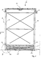
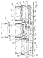
- a rack storage 11 for cassettes 12 containing rod-shaped material essentially consists of shelves 13 arranged next to one another transversely to the longitudinal extent of the cassettes 12 and separated from one another by rack aisles 14.
- the shelves have support arms 15 (see also FIG. 23) which extend horizontally and transversely to the longitudinal direction of the material in the adjacent shelf aisle to form shelf compartments for the cassettes 12, the cassettes engaging with end supports 16 in the form of a U-shaped profile can be brought with the support arms 15.
- the support arms 15 are fastened to terminal supports 17 of the shelves 13, which are connected to one another at their upper end by rails 18 for a storage and retrieval unit 19.
- This storage and retrieval unit 19 is essentially an overhead crane with a lowerable load beam 20 on both sides of the shelves (see FIGS. 7 to 14), load beams 20 being guided over rollers 21 on the shelf supports 17 and also from DE OS 36 02 201 known manner bear fork-shaped load-carrying means 22 which can be brought into engagement with the supports 16 of the cassettes 12. It goes without saying that the load bars 20 arranged on both sides of the shelves 13, which can be raised and lowered via chains 23 starting from the crane 19, are synchronized with one another with regard to their movements.
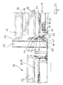
- the juxtaposed arrangement of shelves 13 can be passed underneath along a track 24 arranged between the shelf supports 17 transversely to the longitudinal extent of the cassettes 12 by a transport carriage 25, which is shown in FIGS. 1 and 2 overall in a transverse or end view, the details of which, however, are based on 4 to 6 can be explained.
- the transport carriage has a frame-shaped chassis 30 on which there are three receiving places 1, 2, 3 for cassettes 12.
- the middle recording place is between two levels can be raised and lowered with the aid of, for example, cylinder-piston units 31, 32, the stroke range being greater than the height of a cassette.
- the receiving space is essentially formed from a receptacle 33 which can be moved vertically with respect to the base frame or chassis 30 via scissor levers 34 which, in a manner known per se, by the cylinders shown in FIG. Piston units 31, 32 can be actuated.
- the receptacle 33 carries rollers 35, via which the cassette 12 can be moved transversely to the longitudinal extent of the rod-shaped material contained in the cassette.
- the rollers 35 can be driven in rotation in both directions.
- the receiving places 2 and 3 have rollers 36, 37 which can be driven in both directions, so that when the scissor levers 34 are lowered, the cassettes 12 can be exchanged between the receiving places 1, 2 and 3.
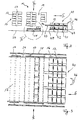
- FIG. 6 also shows how the chassis 30 of the transport carriage can be moved on the rails 24 via wheels 38, 39.
- This station has two receiving planes 42, 43 arranged one above the other on a frame 41 for the cassettes 12, in which case both receiving planes are equipped with roller conveyors 44, 45 which can be driven in both directions and which are connected to the rollers or roller conveyors 35, 36 and 37 of the Transport carriage 25 correspond.
- the upper receiving plane 43 is longer than the lower receiving plane 42 by a cassette width in the direction of the transport carriage 25, so that the transport carriage 25 can approach the lower receiving plane 42 with its receiving station 3 (see FIG. 6) , while at the same time the receiving space 1 in its raised position fits the receiving plane 43.
- the receiving planes 42, 43 have space for a plurality of cassettes arranged next to one another.
- the last cassette space facing an operator 46 is formed by an elevator 47, which is only shown schematically and can be used to bring cassettes from the upper receiving plane 43 to the lower receiving plane 42 or vice versa.
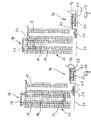
- FIGS. 7 to 20 these figures each showing a side view of a section of a shelf storage in the illustration according to FIG. 2.
- the transport carriage 25 brings a cassette B, which was previously removed from the lower receiving plane 42 and is in the receiving station 3 (see FIG. 6) of the transport carriage 25, back into the rack storage 11 in accordance with the direction of the arrow shown.
- the cassette B is then moved from the (with reference to FIG. 6) receiving space 3 by actuating the rollers 35 to 37 to the receiving space 2.
- the storage and retrieval unit 19 picks up a new cassette A from one of the shelves via the load bars 20 and the load-carrying means 22 located thereon.
- the transport carriage 25 with its central receiving position 1 reaches the foot end of the rack aisle 14 belonging to the cassette A, whereupon the storage and retrieval device 19 according to FIG. 10 places the next succeeding cassette A on the central receiving station 1 of the transport carriage.
- the transport carriage 25 moves according to FIG. 11 by a cassette width so that the storage and retrieval device can accommodate the cassette B to be returned on its support means 16, as shown in FIG. 12.
- the cassette B to be returned can be returned to the place previously occupied by the cassette A by the storage and retrieval unit 19.
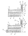
- the transport carriage can now drive with the cassette A to the station 40, as can be seen in FIG. 14, which it then reaches in the position shown in FIG. 15.
- the cassette A is raised to the level of the upper receiving plane 43 by actuating the scissors levers 34 according to FIGS. 4 and 5, in order to be transferred from the transport carriage to the upper receiving plane by actuating the rollers 35 on the one hand and the roller conveyor 44 on the other hand .
- a next cassette C which has already been processed at the station, is transferred from the lower receiving plane 42 by actuating the roller tracks 45 and the rollers 37 to the receiving location 3 of the transport carriage 35, as shown in FIG. 16.
- the receiving space 1 is lowered again according to FIG. 17, and according to FIG. 18 the transport trolley can move down to the rack warehouse for the next round.
- a cassette G used up according to FIG. 17 can be lowered in the manner shown in FIG. 18 by the elevator 47 to the lower receiving plane 42 as seen from Fig. 18 is. Then, by operating the roller conveyor 45, the cassette G is taken down from the elevator to the lower receiving level in the manner shown in FIG. 19. Now the elevator 47 moves up again, so that the next cassettes of the upper receiving level can be moved up by operating the roller conveyor 44. As a result, as shown in FIG. 20, the next cassette 1 is available on the lower receiving level for returning to the rack storage, while on the upper receiving level there is space for the cassette to be next fed to station 40.
- the cassette change between the trolley 25 and the station 40 takes place in a short working cycle without the trolley 25 having to be moved additionally.
- this cassette change corresponds only to the short time required, as was also necessary according to FIGS. 7 to 12 within the rack warehouse.
- the device described so far is placed on rows of shelves which are only provided with a station for storing and retrieving the material contained in the cassettes at their front end lying transversely to the longitudinal direction of the material.
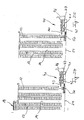
- the two other cassette positions 2 and 3 are basically given by a corresponding contact surface of the transport carriage 50 for the cassettes 12, which, as can best be seen from FIG. 21, are given by bars 59 transverse to the longitudinal direction of the cassettes.
- the transport carriage 50 also has, in the region of both end faces of the cassettes 12, outer rails 60 carried by frame-fixed webs 61, by means of which carriages 62 of a transfer device for the cassettes can be moved on the transport carriage 50 transversely to the longitudinal extent of the cassettes 12.
- the carriages 62 of the transfer device can be adjusted in height via vertical, length-adjustable stands 63 with carriages 64 movable on the outer rails 60 and via a respective cylinder-piston unit 65, which on the one hand on the top of the carriage 62 and on the other hand in the area of the respective Running gear 64 is pivotally articulated.
- the carriages 62 also have on both sides the support bracket 70 assigned to the two end faces of the respective cassette 12 for support and longitudinal and, if appropriate, transverse adjustment of the respective cassette, the horizontal leg 71 of which underpins the cassette while its vertical leg 72 is the system against the cassette end wall.
- the vertical leg 72 of the support bracket 70 can expediently be inclined or beveled in the region of its upper, free end from the cassette end wall.
- a cassette 12 can be moved back and forth between the positions 1, 2 and 3 by means of the transfer device (carriage 62) by the action of the cylinder-piston Aggregates 65 raised the respective cassette and is moved along the outer rails 60 by driving the trolleys 64.
- 21 and 22 also show the synchronous, reciprocating drive of the carriages 62 via a motor 73 fastened to the transport carriage 50, which drives a shaft 75 via a chain 74, via the end spur gears 76 of which at both ends of the transport carriage an endless one Chain 77 rotates, which is guided over deflection wheels 78, 79, 80 with its lower, horizontally continuous run through a coupling 81 to the carriage 62.
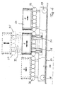
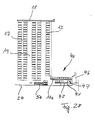
- an unloading station 51 is arranged on the outside of the rack storage. As shown in the top view according to FIG. 23, this has two places 90, 91 next to one another, which are considered to be in the longitudinal direction direction of the material running roller conveyors are formed. On one of these roller conveyors, the transport carriage 50 can deliver a cassette 12 from its central receiving location 1 by the rollers 57 of this receiving location being driven accordingly by the motor 57.
- the middle receiving space 1 can be adjusted in height by scissor levers 95, which are articulated on the one hand on a frame 96 carrying the rollers 56 and on the other hand on the frame 59 of the transport carriage 50.
- the scissor levers can in turn be actuated in a manner known per se, for example by a cylinder-piston unit (not shown).
- the frame 96 has a shortened extent in the material longitudinal direction or in the longitudinal direction of the cassettes 12, so that the ends of the cassettes 12 having the supports 16 can protrude freely. One reason for this is so that the carriage 62 forming the transfer device can move freely past the frame 96.
- this also means that a station of the type already described can receive the cassettes with its roller conveyors.
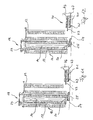
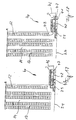
- FIGS. 24 to 28 For this and for the mode of operation of the storage and retrieval station in connection with the transport carriage explained with reference to FIGS. 21 to 23, reference is made to FIGS. 24 to 28. Imagine that the trolley has brought a new cassette A towards the station for storage and retrieval in the manner already described with reference to FIGS. 7 to 15.
- frame 96 with cassette A located thereon is raised into the position shown in FIG. 25, after which it can then be moved into the position shown in FIG. 26.
- the formation of the roller conveyor 100 of the upper receiving plane 43 is made at least at the left first place so that the frame 96 can move in between the rollers 100, ie these rollers only support the respective cassette at their two longitudinal ends.
- at least the front position of the upper receiving plane 43 of the station 40 facing the transport carriage is open in the form of a fork in the direction of the shelves in such a way that the frame 96 can move in between the fork legs.
- the cassette A is placed on the upper receiving plane 43 by lowering the frame 96.
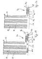
- the transfer device described with reference to FIGS. 21 and 22 can lift a cassette C to be returned from the lower receiving plane 42 of the station 40, here the roller conveyor 45 of the lower receiving plane, seen in the longitudinal direction of the material, must lie within the area occupied by the support bracket 72.
- the ends of the cassettes must protrude freely beyond the roller conveyor 45 in order to be able to be gripped by the transfer device or its support bracket 72.
Landscapes
- Engineering & Computer Science (AREA)
- Mechanical Engineering (AREA)
- Warehouses Or Storage Devices (AREA)
- Intermediate Stations On Conveyors (AREA)
Description
Die Erfindung betrifft ein Regallager für in selbsttragenden Kassetten aufgenommes, stangen- oder plattenförmiges Material mit mehreren quer zur Materiallängsrichtung fluchtend nebeneinander angeordneten und durch Regalgänge voneinander getrennten Regalen, die übereinander an vertikalen Regalstützen befestigte, sich horizontal quer zur Materiallängsrichtung in den benachbarten Regalgang erstreckende Tragarme zur Bildung von Regalfächern für die Kassetten und dazu für den Eingriff in stirnseits vorstehende Auflagen der Kassetten aufweisen, ferner mit einem oberhalb bzw. seitlich der Regale quer zur Materiallängsrichtung verfahrbaren Regalbediengerät, durch das die Auflagen der Kassetten stirnseitig untergreifbar sowie die Kassetten quer zu den Regalgängen und in diesen auf- und abbewegbar sind, weiterhin mit einem unterhalb der untersten Regalfächer quer zur Materiallängsrichtung verfahrbaren Transportwagen mit wenigstens zwei nebeneinander angeordneten Aufnahmeplätzen für die Kassetten, sowie schließlich mit mindestens einer in Fahrtrichtung des Transportwagens außerhalb der Regale angeordneten und durch den Transportwagen mit den Kassetten anfahrbaren Station zum Ein- und Auslagern für das in den Kassetten enthaltene Material, wobei diese Station eine erste, dem Niveau des Transportwagens im wesentlichen entsprechende Aufnahmeebene zum Wechsel der Kassetten zwischen Transportwagen und Station zum Ein- und Auslagern aufweist.The invention relates to a rack storage for self-supporting cassettes, rod-shaped or plate-shaped material with a plurality of racks arranged in alignment transversely to the longitudinal direction of the material and separated from one another by rack aisles, which are mounted one above the other on vertical rack supports and which extend horizontally across the longitudinal direction of the material into the adjacent rack aisle Formation of shelves for the cassettes and for this purpose to engage in protruding supports of the cassettes, furthermore with a shelf operating device which can be moved transversely to the longitudinal direction of the material above or to the side of the shelves, through which the supports of the cassettes can be gripped on the front and the cassettes transversely to the rack aisles and can be moved up and down in these, furthermore with a transport trolley which can be moved transversely to the longitudinal direction of the material underneath the lowermost shelf compartments and has at least two receptacles f for the cassettes, and finally with at least one station arranged outside the shelves in the direction of travel of the transport carriage and accessible by the transport carriage with the cassettes for storing and retrieving the material contained in the cassettes, this station being a first, the level of the transport carriage in has essentially corresponding receiving level for changing the cassettes between the trolley and station for storage and retrieval.
Eine solche Einrichtung ist Gegenstand der älteren deutschen Patentanmeldung P 39 22 964.5, die in Verbesserung des Gegenstandes der DE-OS 37 08 401 eine Möglichkeit angibt, wie der Wechsel zwischen einer in das Regallager einzulagernden Kassette einerseits und einer aus dem Regallager nächstfolgend herauszubringenden Kassetten andererseits schneller erfolgen kann. Dazu können die Kassetten auf dem Transportwagen während dessen Fahrt zwischen Auslagerstation und Regallagerdurch entsprechende Mittel umgesetzt werden, damit bei einem einzigen Treffpunkt zwischen Transportwagen und Regalbediengerät sowohl die nächstfolgende Kassette auf dem Transportwagen abgesetzt werden kann als auch die zurückgebrachte Kassette vom Transportwagen abgenommen werden kann, um dann an den Platz innerhalb des Regallagers gebracht zu werden, von dem die nächstfolgend aus dem Regallager herauszubringende Kassette entnommen wurde. Damit verbindet sich zwar eine chaotische Lagerung der Kassetten, die jedoch zu einer Reduzierung der für den Kassettenwechsel erforderlichen Fahrzeiten bzw. -bewegungen von Transportwagen einerseits und Regalbediengerät andererseits auf ein absolutes Minimum führt mit der Folge, daß beide genannten Einrichtungen nicht nur im Zuge des Kassettenwechsels innerhalb der ohnehin notwendigen Fahrbewegungen glatt bzw. harmonisch miteinander spielen sondern auch in Begleitung des Kassettenwechsels nur solche Fahrbewegungen ausführen, die ohnehin notwendig sind.Such a device is the subject of the older German
Im Falle der älteren Anmeldung bzw. im vorbekannten Falle ist die Station zum Ein- und Auslagern bzw. zum Weiterverarbeiten des in den Kassetten enthaltenen Materials in Längsrichtung des Materials neben dem Regallager angeordnet, so daß die Kassetten vom Transportwagen in Längsrichtung des Materials beispielsweise mit Hilfe einer Rollenbahn auf diese Station herausgefahren werden. Soll jedoch das Regallager mehrere in Längsrichtung des Materials dicht nebeneinander liegende Blöcke aufweisen, so besteht die Möglichkeit für eine derartige Station nur für eine äußere Regalreihe, während für die anderen Regalreihen ein Ausfahren der Kassetten nur über die quer zur Materiallängsrichtung gelegenen Stirnseiten der Regalreihen möglich ist.In the case of the older application or in the previously known case, the station for storing and retrieving or for further processing of the material contained in the cassettes is arranged in the longitudinal direction of the material next to the rack warehouse, so that the cassettes from the trolley in the longitudinal direction of the material, for example, with the help a roller conveyor can be moved out to this station. However, if the shelf storage should have several blocks lying closely next to one another in the longitudinal direction of the material, the possibility exists for such a station only for an outer row of shelves, while for the other rows of shelves, the cassettes can only be extended via the end faces of the rows of shelves lying transversely to the material longitudinal direction .
Hierzu enthält die genannte ältere deutsche Patentanmeldung einen einfachen, stirnseitigen Auslagerplatz, der jedoch nur die Handhabung einer Kassette beispielsweise zum Wiederauffüllen mit neuem Material ermöglicht. Mit einem solchen Auslagerplatz erfordert jedoch das Ein- und Auslagern des Materials verhältnismäßig viel Zeit und ist umständlich.For this purpose, the older German patent application mentioned contains a simple, front-side removal location, which, however, only enables the handling of a cassette, for example for refilling with new material. With such a swap space, however, the storage and retrieval of the material takes a relatively long time and is cumbersome.
Aufgabe der Erfindung ist es daher, eine stirnseitige Station zum Ein- und Auslagern für in selbsttragenden Kassetten aufgenommenes Material zu schaffen, die in Verbindung mit dem geschilderten Transportwagen einen schnellen Wechsel zwischen wenigstens zwei Kassetten erlaubt und gegebenenfalls auch die Möglichkeit bietet, daß eine Bedienungsperson ohne Probleme - gegebenenfalls mit Hilfe einer Pufferzone - mehrere Kassetten vorgelagert hat und aus diesen kommissionieren bzw. diese einlagern kann. Insgesamt soll durch die Erfindung die stirnseitige Station zum Ein- und Auslagern so ausgebildet sein, daß die Funktion und Wirkungsweise des Transportwagens beibehalten werden kann und die Spielzeiten sowie die Leistungsfähigkeit des gesamten Regallagers nicht durch diese Station beschränkt wird.The object of the invention is therefore to provide a front-end station for storing and retrieving material contained in self-supporting cassettes, which in connection with the transport trolley described allows a quick change between at least two cassettes and possibly also offers the possibility that an operator without Problems - possibly with the help of a buffer zone - has stored several cassettes in front of them and can pick or store them. All in all, the invention is intended to design the end station for storing and retrieving in such a way that the function and mode of operation of the transport carriage can be maintained and the seasons and the performance of the entire rack warehouse are not restricted by this station.
Diese Aufgabe ist ausgehend von dem eingangs genannten Regallager erfindungsgemäß dadurch gelöst, daß die Station zum Ein- und Auslagern zwei übereinander angeordnete Aufnahmeebenen für die Kassetten aufweist, wobei die untere Aufnahmeebene der ersten eingangs genannten Aufnahmeebene entspricht, daß die obere Aufnahmeebene die untere Aufnahmeebene in Richtung auf den Transportwagen um eine Kassettenbreite überragt, daß der Transportwagen auf dem in seiner Fahrtrichtung gegenüber der Station zum Ein-und Auslagern zurückliegenden Aufnahmeplatz eine Hubvorrichtung zur Anhebung der dortigen Kassette auf das Niveau der oberen Aufnahmeebene aufweist, und daß die Aufnahmeebenen sowie der Transportwagen mit Mitteln zum Wechseln der Kassetten zwischen den Aufnahmeebenen und dem Transportwagen ausgerüstet sind.Starting from the rack storage system mentioned at the outset, this object is achieved according to the invention in that the storage and retrieval station has two receiving planes for the cassettes which are arranged one above the other, the lower receiving plane corresponding to the first receiving plane mentioned at the outset that the upper receiving plane is in the direction of the lower receiving plane towering over the trolley by a cassette width, that the trolley has a lifting device for lifting the cassette there to the level of the upper receiving level in the direction of travel opposite the storage and retrieval station, and that the receiving levels and the trolley with means for changing the cassettes between the receiving levels and the trolley are steady.
Durch diese erfindungsgemäßen Maßnahmen kann der Transportwagen bei der Station zum Ein- und Auslagern gleichzeitig mit Hilfe der Hubvorrichtung eine Kassette auf der oberen Aufnahmeebene absetzen und mit seinem in Richtung auf die Station zum Ein- und Auslagern daneben liegenden Aufnahmeplatz eine Kassette von der unteren Aufnahmeebene abnehmen. Dadurch ist auch im Bereich der Station zum Ein- und Auslagern ein zügiger Kassettenwechsel zwischen herauszubringendem Material und wieder in das Regallager zurückzubringenden Material möglich, ohne daß es dazu weiterer Nebenzeiten bzw. Fahrbewegungen des Transportwagens bedürfte.By means of these measures according to the invention, the transport trolley at the storage and retrieval station can simultaneously set down a cassette on the upper receiving level with the aid of the lifting device and remove a cassette from the lower receiving level with its receiving space which is adjacent to the storage and retrieval station . As a result, a rapid cassette change between the material to be removed and the material to be returned to the rack storage is also possible in the area of the storage and retrieval station without the need for additional idle times or travel movements of the transport trolley.
Im Sinne der Aufgabe ist es zweckmäßig, daß auf den Aufnahmeebenen der Station zum Ein- und Auslagern quer zur Materiallängsrichtung mehrere Kassetten aufnehmbar sind, und daß die Aufnahmeebene Mittel zur Verschiebung der Kassetten quer zur Materiallängsrichtung aufweisen. Damit kann auf beiden Aufnahmeebenen ein größeres Kassettenangebot vorhanden sein, so daß die an der Station zum Ein- und Auslagern tätige Bedienungsperson zumindest kurzfristig nicht auf einen einzelnen Kassettenwechsel zwischen Transportwagen und Station angewiesen ist.For the purpose of the task, it is expedient that several cassettes can be accommodated transversely to the longitudinal direction of the material on the receiving planes of the station for storage and retrieval, and that the receiving plane have means for displacing the cassettes transversely to the longitudinal direction of the material. Thus, a larger range of cassettes can be present on both receiving levels, so that the operator working at the station for storage and retrieval does not have to rely, at least for a short time, on a single cassette change between the trolley and the station.
Die Verschiebemittel der Station zum Ein- und Auslagern können durch eine in beiden Drehrichtungen antreibbaren Rollenbahn bzw. entsprechende Rollenbahnabschnitte gebildet sein. Durch eine solche Rollenbahn bzw. die genannten Rollenbahnabschnitte lassen sich die Kassetten quer zur Längsrichtung des Materials stückweise an den Arbeitsplatz der Bedienungsperson verschieben bzw. wieder von diesem fortbewegen. Diese Vorgehensweise kann die Bedienungsperson durch Ein- bzw. Ausschalten der Rollenbahn selbst je nach Arbeitslage bestimmen.The displacement means of the station for storage and retrieval can be formed by a roller conveyor that can be driven in both directions of rotation or corresponding roller conveyor sections. By means of such a roller conveyor or the roller conveyor sections mentioned, the cassettes can be moved piece by piece to the longitudinal direction of the material to the operator's workplace or moved away from it again. The operator can determine this procedure by switching the roller conveyor on or off, depending on the working situation.
Alternativ zu Rollenbahnen können selbstverständlich auch andere Mittel zur Verschiebung der Kassetten quer zur Längserstreckung des Materials Einsatz finden. Beispielsweise kann es in diesem Zusammenhang auch vorteilhaft sein, daß die Verschiebemittel durch eine in beiden Richtungen quer zur Materiallängsrichtung antreibbaren Vorrichtung nach Art eines Kettenförderers bzw. entsprechender Kettenfördererabschnitte gebildet sind.As an alternative to roller conveyors, other means of moving the cassettes transversely to the longitudinal extent of the material can of course also be used. For example, it can also be advantageous in this context that the displacement means are formed by a device which can be driven in both directions transversely to the longitudinal direction of the material, in the manner of a chain conveyor or corresponding chain conveyor sections.
Ebenso kommen hier Hubbalkenförderer, Stauförderer, Schleppketten oder dergleichen in Frage.Walking beam conveyors, accumulation conveyors, drag chains or the like are also suitable here.
Zum Wechsel der Kassetten zwischen den beiden Aufnahmeebenen der Station zum Ein- und Auslagern ist es vorteilhaft, daß an dem dem Transportwagen abgewandten Ende der Aufnahmeebenen der letzte Kassettenplatz durch einen beiden Ebenen gemeinsamen, vertikal fahrbaren Aufzug zum Wechseln der Kassetten zwischen den beiden Ebenen gebildet ist. Die Betätigung dieses Aufzugs ist unabhängig von den Fahrbewegungen des Transportwagens und kann von der Bedienungsperson im Rahmen des Ein- und Auslagerns je nach Arbeitslage erfolgen.To change the cassettes between the two receiving levels of the station for storage and retrieval, it is advantageous that at the end of the receiving levels facing away from the transport carriage, the last cassette location is formed by a vertically movable elevator common to both levels for changing the cassettes between the two levels . The operation of this elevator is independent of the travel movements of the trolley and can be carried out by the operator as part of the loading and unloading depending on the working situation.
Was die passende Ausbildung des Transportwagens betrifft, so ist es zweckmäßig, daß die Hubvorrichtung des Transportwagens in beiden Richtungen drehantreibbare Rollen zum Kassettenwechsel zwischen Hubvorrichtung und oberer Aufnahmeebene bzw. gegenüber einem benachbarten Aufnahmeplatz des Transportwagens aufweist. Dabei kann die Hubvorrichtung eine im wesentlichen der Außenkontur des Aufnahmeplatzes des Transportwagens entsprechende, sich horizontal erstreckende Aufnahme aufweisen, die über Hubmittel gegenüber dem Transportwagen heb- und senkbar ist. Hier kann die Aufnahme an ihren den Längsenden der Kassetten zugeordneten Enden die in beiden Drehrichtungen antreibbaren Rollen zum Kassettenwechsel aufweisen.As far as the appropriate design of the trolley is concerned, it is expedient that the lifting device of the trolley has rollers which can be rotated in both directions for changing the cassette between the lifting device and the upper receiving plane or opposite an adjacent receiving space of the trolley. In this case, the lifting device can have a horizontally extending receptacle which essentially corresponds to the outer contour of the receiving location of the transport carriage and which can be raised and lowered relative to the transport carriage by means of lifting means. Here, the receptacle can have at its ends assigned to the longitudinal ends of the cassettes the rollers which can be driven in both directions of rotation for changing the cassette.
Was die Ausbildung der Hubvorrichtung betrifft, so kann diese bzw. die genannte Aufnahme über verstellbare Scherenhebel am Transportwagen vertikal verstellbar angelenkt sein, wobei die Vertikalverstellung der Scherenhebel in an sich bekannter Weise, beispielsweise über Zylinder-Kolben-Aggregate, Stellspindeln oder dergleichen erfolgen kann.With regard to the design of the lifting device, this or the above-mentioned receptacle can be articulated vertically adjustably on the transport trolley via adjustable scissor levers, the vertical adjustment of the scissor levers being able to take place in a manner known per se, for example using cylinder-piston units, adjusting spindles or the like.
Passend hierzu kann jeder der der Hubvorrichtung benachbarten Aufnahmeplätze des Transportwagens ebenfalls in beiden Richtungen drehantreibbarer Rollen zum Kassettenwechsel aufweisen.Appropriately for this purpose, each of the receiving locations of the transport carriage adjacent to the lifting device can also have rollers that can be driven in both directions for changing the cassette.
Eine andere Ausbildung des Transportwagens kann so gestaltet sein, daß auf dem Transportwagen eine quer zur Materiallängsrichtung bewegbare Umsetzvorrichtung für die Anhebung und Überbringung einer auf einem Aufnahmeplatz des Transportwagens befindlichen Kassette auf einen anderen Aufnahmeplatz des Transportwagens bzw. zurAbnahme einer Kassette von dem zugeordneten Ende der unteren Aufnahmeebene der Station zum Ein- und Auslagern auf den entsprechenden Aufnahmeplatz des Transportwagens angeordnet ist. Hier ist also die Umsetzvorrichtung das Äquivalent zu den vorerwähnten drehantreibbaren Rollen.Another design of the trolley can be designed such that a transfer device movable transversely to the longitudinal direction of the material on the trolley for lifting and transferring a cassette located in one receiving location of the trolley to another receiving location of the trolley or for removing a cassette from the assigned end of the lower one Receiving level of the station for storage and retrieval is arranged on the corresponding receiving place of the transport carriage. So here the transfer device is the equivalent of the aforementioned rotatably driven rollers.
Zur Ausbildung der Umsetzvorrichtung kann vorgesehen sein, daß diese bei den Längsenden der Kassetten zugeordnet je einen entlang äußeren Schienen des Transportwagens verfahrbaren Schlitten zur Aufnahme einer Kassette aufweist. Hier kann vorgesehen sein, daß jeder Schlitten über vertikale, längenveränderbare Ständer mit auf den äußeren Schienen bewegbaren Fahrwerken in Verbindung steht und über Zylinder-Kolben-Aggregate höhenverstellbar ist, die einerseits am Schlitten und andererseits im Bereich der Fahrwerke schwenkbar angelenkt sind.In order to form the transfer device, it can be provided that, at the longitudinal ends of the cassettes, they each have a slide that can be moved along outer rails of the transport carriage for receiving a cassette. It can be provided here that each slide is connected via vertical, length-adjustable stands to movable undercarriages on the outer rails and is height-adjustable by means of cylinder-piston assemblies which are pivotably articulated on the one hand on the slide and on the other hand in the area of the undercarriages.
Dabei kann jeder Schlitten den beiden Stirnseiten an der Kassette zugeordnete Stützwinkel zur Auflagerung und Längs- bzw. Querjustierung der Kassette aufweisen, deren waagerechter Schenkel die Kassette unterfängt, während ihr vertikaler Schenkel in Anlage gegen die Kassettenstirn- bzw. -seitenwand ist.Each carriage can have support brackets assigned to the two end faces on the cassette for supporting and longitudinal or transverse adjustment of the cassette, the horizontal leg of which underpins the cassette, while its vertical leg is in contact with the cassette end or side wall.
Der vertikale Schenkel der Stützwinkel kann im Bereich seines freien Endes von der Kassettenstirn- bzw. -seitenwand fortgeneigt abgeschrägt sein, um ein leichteres Ausgleichen eines eventuellen Versatzes der Kassetten zu ermöglichen.In the area of its free end, the vertical leg of the support bracket can be inclined away from the front or side wall of the cassette in order to make it easier to compensate for any offset of the cassettes.
Für den Fall, daß bei einer äußeren Regalreihe auch eine in Materiallängsrichtung neben den Regalen auf der Höhe des Transportwagens angeordnete Ein- und Auslagerstation gegebenenfalls zur gleichzeitigen Aufnahme zweier nebeneinander angeordneter Kassetten vorgesehen werden soll, kann es in Ergänzung der vorstehend angegebenen Bauformen vorteilhaft sein, daß der die Hubvorrichtung aufweisende Aufnahmeplatz des Transportwagens bei abgesenkter Stellung der Hubvorrichtung wirksame Mittel zum Wechsel einer Kassette zwischen Ein- und Auslagerstation und Transportwagen aufweist. Diese Mittel können beispielsweise durch eine in beiden Richtungen drehantreibbare Rollenbahn gebildet sein.In the event that a storage and retrieval station arranged in the longitudinal direction of the material next to the shelves at the level of the transport carriage is to be provided for the simultaneous reception of two cassettes arranged next to one another, it may be advantageous to supplement the above-mentioned designs that the receiving space of the trolley having the lifting device, when the lifting device is in the lowered position, has effective means for changing a cassette between the storage and retrieval station and the trolley. These means can be formed, for example, by a roller conveyor which can be driven in rotation in both directions.
Für die Anwendung dieser Konstruktion ist es zweckmäßig, daß der die Hubvorrichtung aufweisende Aufnahmeplatz zwischen bezogen auf die Materiallängsrichtung gegenüber der Hubvorrichtung außen liegende Fördermittel der oberen Aufnahmeebene von deren den Regalen zugewandten Ende aus einfahrbar ist.For the use of this construction, it is expedient that the receiving space having the lifting device can be moved in between the conveying means of the upper receiving level lying outside in relation to the longitudinal direction of the material relative to the lifting device, from the end thereof facing the shelves.
Vorstehend ist jeweils nur eine Station zum Ein- und Auslagern des in den Kassetten enthaltenen Materials angesprochen worden. Selbstverständlich umfaßt die Erfindung aber auch die Möglichkeit, derartige Stationen an beiden Enden des Fahrweges des Transportwagens vorzusehen.Only one station for storing and retrieving the material contained in the cassettes has been addressed above. Of course, the invention also includes the possibility of providing such stations at both ends of the route of the trolley.
Weitere erfindungswesentliche Merkmale und Einzelheiten ergeben sich aus der nachfolgenden Beschreibung von Ausführungsformen anhand der Zeichnung. In der Zeichnung zeigen:
- Fig. 1 die Queransicht eines Regallagers entsprechend der Pfeilrichtung in den Fig. 2 bzw. 3;
- Fig. 2 die vereinfachte Vorderansicht des Regallagers gemäß der Pfeilrichtung 11 in Fig. 1 bzw. 3;
- Fig. 3 die Oberansicht des Regallagers gemäß der Pfeilrichtung 111 in Fig. 1 bzw. Fig. 2;
- Fig. 4 die vergrößerte, teilweise Darstellung des Ausschnittes IV in Fig. 1;
- Fig. 5 den Gegenstand gemäß Fig. 4 in einer anderen Arbeitsstellung;
- Fig. 6 eine vergrößerte Ansicht des Transportwagens nach Art eines Ausschnittes VI in Fig. 2;
- Fig. 7 bis 20 den Ablauf eines Kassettenwechsels mit einem Lastspiel;
- Fig. 21 eine andere Ausführungsform des Erfindungsgegenstandes in der Darstellung nach dem Ausschnitt IV gemäß Fig. 1;
- Fig. 22 eine Stirnansicht des aus Fig. 21 ersichtlichen Transportwagens nach Art der Ansicht Vl in Fig. 2;
- Fig. 23 eine Draufsicht auf eine Einrichtung gemäß Fig. 21 und
- Fig. 24 bis 28 einen Kassettenwechsel mit Hilfe derAusführungsform des Transportwagens gemäß den Fig. 21 und 22.
- Figure 1 shows the transverse view of a shelf warehouse according to the direction of the arrow in Figures 2 and 3;
- FIG. 2 shows the simplified front view of the rack store according to the direction of arrow 11 in FIGS. 1 and 3;
- 3 shows the top view of the rack storage according to the arrow direction 111 in FIG. 1 or FIG. 2;
- 4 shows the enlarged, partial illustration of section IV in FIG. 1;
- 5 shows the object according to FIG. 4 in a different working position;
- FIG. 6 shows an enlarged view of the transport carriage in the manner of a section VI in FIG. 2;
- 7 to 20 the sequence of a cassette change with a load cycle;
- FIG. 21 shows another embodiment of the subject of the invention in the illustration according to section IV according to FIG. 1;
- FIG. 22 shows an end view of the transport carriage shown in FIG. 21 in the manner of view VI in FIG. 2;
- 23 is a top view of a device according to FIGS. 21 and
- 24 to 28 a cassette change using the embodiment of the trolley according to Figs. 21 and 22.
Gemäß den Fig. 1 bis 3 besteht ein Regallager 11 für stangenförmiges Material enthaltende Kassetten 12 im wesentlichen aus quer zur Längserstreckung der Kassetten 12 nebeneinander angeordneten Regalen 13, die über Regalgänge 14 voneinander getrennt sind.According to FIGS. 1 to 3, a rack storage 11 for
Die Regale weisen sich horizontal und quer zur Materiallängsrichtung in den jeweils benachbarten Regalgang erstreckende Tragarme 15 (siehe auch Fig. 23) zur Bildung von Regalfächern für die Kassetten 12 auf, wobei die Kassetten mit stirnseitigen Auflagen 16 in Form einer U-förmigen Profilierung in Eingriff mit den Tragarmen 15 bringbar sind.The shelves have support arms 15 (see also FIG. 23) which extend horizontally and transversely to the longitudinal direction of the material in the adjacent shelf aisle to form shelf compartments for the
Diese Art der Kassettenlagerung und -ausbildung ist bekannt und im einzelnen beispielsweise in der DE-OS 36 02 201 beschrieben, so daß darauf hier im einzelnen nicht mehr eingegangen zu werden braucht.This type of cassette storage and training is known and described in detail, for example, in DE-OS 36 02 201, so that there is no need to go into detail here.
Die Tragarme 15 sind an endständigen Stützen 17 der Regale 13 befestigt, die an ihrem oberen Ende außen durch Laufschienen 18fürein Regalbediengerät 19 miteinanderverbunden sind. Dieses Regalbediengerät 19 ist im wesentlichen ein über Kopf laufender Kran mit an beiden Seiten der Regale je einem absenkbaren Lastbalken 20 (siehe Fig. 7 bis 14), wobei Lastbalken 20 über Laufrollen 21 an den Regalstützen 17 geführt sind und in ebenfalls aus der DE-OS 36 02 201 bekannten Weise gabelförmige Lastaufnahmemittel 22 tragen, die mit den Auflagen 16 der Kassetten 12 in Eingriff bringbar sind. Es versteht sich von selbst, daß die beidseits der Regale 13 angeordneten Lastbalken 20, die ausgehend vom Kran 19 über Ketten 23 heb- und senkbar sind, bezüglich ihrer Bewegungen miteinander synchronisiert sind.The
Die nebeneinanderstehenden Anordnung von Regalen 13 ist entlang zwischen den Regalstützen 17 angeordneter Fahrbahn 24 quer zur Längserstreckung der Kassetten 12 durch einen Transportwagen 25 unterfahrbar, der in den Fig. 1 und 2 insgesamt in Quer- bzw. Stirnansicht dargestellt ist, dessen Einzelheiten aber eher anhand der Fig. 4 bis 6 erläutert werden können.The juxtaposed arrangement of
Wie aus Fig. 6 ersichtlich, hat der Transportwagen ein rahmenförmiges Fahrgestell 30, auf dem sich drei Aufnahmeplätze 1,2,3 für Kassetten 12 befinden. Dabei ist der mittlere Aufnahmeplatz zwischen zwei Ebenen heb- und senkbar mit Hilfe von beispielsweise Zylinder-Kolben-Aggregaten 31, 32, wobei der Hubbereich größer als die Höhe einer Kassette ist.As can be seen from FIG. 6, the transport carriage has a frame-shaped
Die Fig. 4 und 5 zeigen diesen mittleren Aufnahmeplatz einmal in der angehobenen und einmal in der unteren Stellung. Dabei ist aus diesen Figuren auch ersichtlich, daß der Aufnahmeplatz im wesentlichen aus einer Aufnahme 33 gebildet ist, die gegenüber dem Grundrahmen bzw. Fahrgestell 30 über Scherenhebel 34 vertikal bewegbar ist, welche in an sich bekannter Weise durch die aus Fig. 6 ersichtlichen Zylinder-Kolben-Aggregate 31, 32 betätigbar sind.4 and 5 show this middle recording place once in the raised and once in the lower position. It can also be seen from these figures that the receiving space is essentially formed from a
An seinen Stirnenden trägt die Aufnahme 33 Rollen 35, über die die Kassette 12 quer zur Längserstreckung des in der Kassette enthaltenen stangenförmigen Materials verfahren werden kann. Die Rollen 35 sind in beiden Richtungen drehantreibbar.At its ends, the
Entsprechend haben auch die Aufnahmeplätze 2 und 3 in beiden Richtungen drehantreibbare Rollen 36, 37, so daß bei nach unten abgesenkten Scherenhebeln 34 die Kassetten 12 zwischen den Aufnahmeplätzen 1, 2 und 3 gewechselt werden können.Correspondingly, the receiving
Aus Fig. 6 ist noch ersichtlich, wie das Fahrgestell 30 des Transportwagens über Räder 38, 39 auf den Schienen 24 verfahrbar ist.FIG. 6 also shows how the
Wie vereinfacht aus Fig. 2 ersichtlich, schließt sich nun an der quer zur Materiallängsrichtung gelegenen Stirnseite des Regallagers 11 eine insgesamt mit der Ziffer 40 versehene Station zum Ein- und Auslagern des in den Kassetten 12 enthaltenen Materials an, die durch den Transportwagen 25 anfahrbar ist. Diese Station hat zwei übereinander an einem Gestell 41 angeordnete Aufnahmeebenen 42, 43 für die Kassetten 12, wobei in diesem Falle beide Aufnahmeebenen mit in beiden Richtungen drehantreibbaren Rollenbahnen 44, 45 ausgerüstet sind, die mit den Rollen bzw. Rollenbahnen 35, 36 und 37 des Transportwagens 25 korrespondieren.As can be seen in a simplified manner from FIG. 2, the end of the rack storage 11, which is located transversely to the longitudinal direction of the material, is followed by a station, generally provided with the
Wie aus Fig. 2 ersichtlich, ist die obere Aufnahmeebene 43 um eine Kassettenbreite in Richtung auf den Transportwagen 25 länger als die untere Aufnahmeebene 42, so daß der Transportwagen 25 mit seinem Aufnahmeplatz 3 (siehe Fig. 6) an die untere Aufnahmeebene 42 heranfahren kann, während gleichzeitig der Aufnahmeplatz 1 in seiner angehobenen Stellung zu der Aufnahmeebene 43 paßt.As can be seen from FIG. 2, the upper receiving
Wie ferner aus Fig. 2 ersichtlich, haben die Aufnahmeebenen 42, 43 Platz für mehrere nebeneinander angeordnete Kassetten. Schließlich ist ihr einer Bedienungsperson 46 zugewandter letzter Kassettenplatz durch einen nur schematisch dargestellten Aufzug 47 gebildet, durch die Kassetten von der oberen Aufnahmeebene 43 auf die untere Aufnahmeebene 42 bzw. umgekehrt gebracht werden können.As can also be seen from FIG. 2, the receiving
Die Arbeitsweise dieser insgesamt dargestellten Einrichtung sei nun anhand der Fig. 7 bis 20 erläutert, wobei diese Figuren jeweils in Seitenansicht ausschnittweise ein Regallager in der Darstellung gemäß Fig. 2 zeigen.The operation of this device shown overall will now be explained with reference to FIGS. 7 to 20, these figures each showing a side view of a section of a shelf storage in the illustration according to FIG. 2.
Gemäß Fig. 7 bringt der Transportwagen 25 eine Kassette B, die vorher von der unteren Aufnahmeebene 42 abgenommen wurde und auf dem Aufnahmeplatz 3 (siehe Fig. 6) des Transportwagens 25 steht, in das Regallager 11 entsprechend der angezeigten Pfeilrichtung zurück. Bei dieser Fahrbewegung wird dann, wie aus Fig. 8 ersichtlich, die Kassette B von dem (bezogen auf Fig. 6) Aufnahmeplatz 3 durch Betätigung der Rollen 35 bis 37 auf den Aufnahmeplatz 2 umgesetzt. Gleichzeitig nimmt das Regalbediengerät 19 über die Lastbalken 20 und die daran befindlichen Lastaufnahmemittel 22 eine neue Kassette A aus einem der Regale auf.According to FIG. 7, the
Gemäß Fig. 9 erreicht der Transportwagen 25 mit seiner mittleren Aufnahmeposition 1 das Fußende des zur Kassette A gehörenden Regalganges 14, woraufhin das Regalbediengerät 19 gemäß Fig. 10 die nächstfolgende Kassette A auf den mittleren Aufnahmeplatz 1 des Transportwagens absetzt.According to FIG. 9, the
Dann verfährt der Transportwagen 25 gemäß Fig. 11 um eine Kassettenbreite so, daß das Regalbediengerät die zurückzulagernde Kassette B an ihren Auflagemitteln 16 aufnehmen kann, wie dies in Fig. 12 dargestellt ist.Then the
Nunmehr kann einerseits die zurückzulagernde Kassette B durch das Regalbediengerät 19 an den Platz zurückgebracht werden, der vorher von der Kassette A eingenommen wurde.Now, on the one hand, the cassette B to be returned can be returned to the place previously occupied by the cassette A by the storage and
Andererseits kann der Transportwagen nunmehr mit der Kassette A zu der Station 40 fahren, wie aus Fig. 14 ersichtlich, die er dann in der aus Fig. 15 ersichtlichen Position erreicht. Dort wird gemäß Fig. 16 die Kassette A durch Betätigung der Scherenhebel 34 gemäß Fig. 4 und 5 auf das Niveau der oberen Aufnahmeebene 43 angehoben, um durch Betätigung der Rollen 35 einerseits sowie der Rollenbahn 44 andererseits vom Transportwagen auf die obere Aufnahmeebene überbracht zu werden. Gleichzeitig wird aber eine nächste, bei der Station bereits bearbeitete Kassette C von der unteren Aufnahmeebene 42 durch Betätigung der Rollenbahnen 45 sowie der Rollen 37 auf den Aufnahmeplatz 3 des Transportwagens 35 überbracht, wie dies Fig. 16 zeigt.On the other hand, the transport carriage can now drive with the cassette A to the
Nunmehr wird der Aufnahmeplatz 1 gemäß Fig. 17 wieder abgesenkt, und es kann gemäß Fig. 18 der Transportwagen für den nächsten Umlauf in das Regallager abfahren.Now the receiving
Während eines nächsten Kassettenwechsels im Bereich des Transportwagens, der in den Fig. 19 und 20 nur noch angedeutet ist, kann eine gemäß Fig. 17 ausgebrauchte Kassette G in der aus Fig. 18 ersichtlichen Weise durch den Aufzug 47 auf die untere Aufnahmeebene 42 abgesenkt werden, wie dies aus Fig. 18 ersichtlich ist. Danach wird durch Betrieb der Rollenbahn 45 die Kassette G in der aus Fig. 19 ersichtlichen Weise vom Aufzug auf die untere Aufnahmeebene heruntergenommen. Nunmehr fährt der Aufzug 47 wieder nach oben, so daß die nächstfolgenden Kassetten der oberen Aufnahmeebene durch Betrieb der Rollenbahn 44 nachgerückt werden können. Im Ergebnis steht dann gemäß Fig. 20 auf der unteren Aufnahmeebene die nächstfolgende Kassette 1 zur Rückführung in das Regallager zur Verfügung, während auf der oberen Aufnahmeebene ein Platz für die als nächstes der Station 40 zuzuführende Kassette frei ist.During a next cassette change in the region of the transport carriage, which is only indicated in FIGS. 19 and 20, a cassette G used up according to FIG. 17 can be lowered in the manner shown in FIG. 18 by the
Wie ersichtlich, findet also der Kassettenwechsel zwischen Transportwagen 25 und Station 40 in einem kurzen Arbeitszug statt, ohne daß dazu der Transportwagen 25 zusätzlich verfahren werden müßte. Damit entspricht dieser Kassettenwechsel nur dem kurzen Zeiteinsatz, wie er auch gemäß den Fig. 7 bis 12 innerhalb des Regallagers notwendig war.As can be seen, the cassette change between the
Die bisher beschriebene Einrichtung ist abgestellt auf Regalreihen, die lediglich an ihrem quer zur Materiallängsrichtung gelegenen Stirnende mit einer Station zum Ein- und Auslagern des in den Kassetten enthaltenen Materials versehen sind.The device described so far is placed on rows of shelves which are only provided with a station for storing and retrieving the material contained in the cassettes at their front end lying transversely to the longitudinal direction of the material.
Bei mehreren derartiger nebeneinander angeordneter Regalreihen besteht jedoch für eine äußere Regalreihe auch die an sich bekannte Möglichkeit, eine Auslagerstation neben der Regalreihe in Materiallängsrichtung anzuordnen. Um auch diesen Anwendungsfall abzudecken, ist für den Transportwagen eine Ausbildung und Arbeitsweise vorgesehen, wie sie im einzelnen anhand der Fig. 21 bis 28 nachfolgend erläutert wird.In the case of several such rows of shelves arranged next to one another, however, there is also the possibility, known per se, for arranging an unloading station next to the row of shelves in the longitudinal direction of the material for an outer row of shelves. In order to cover this application as well, training and mode of operation are provided for the transport trolley, as will be explained in detail below with reference to FIGS. 21 to 28.
So zeigt Fig. 21 in einer der AusschnittdarsteIIung IV gemäß Fig. 1 entsprechenden Weise einen allgemein mit der Ziffer 50 versehenen Transportwagen, der mit einer Auslagerstation 51 zusammenwirken kann, die in Materiallängsrichtung neben der Regalreihe 11 angeordnet ist. (Siehe hierzu auch Fig. 23.) Hierzu ist der Transportwagen 50 in der insbesondere aus den Fig. 21 und 22 ersichtlichen Weise folgendermaßen ausgebildet:
Der Transportwagen 50 ist auf den bereits erwähnten Schienen 24 verfahrbar mitHilfe von Rädern 52, von denen wenigstens ein Paar durch eineWelle 53 synchronisiert ist, über die auch mit Hilfe einesMotors 54der Fahrantrieb 55 erfolgt. Genausogut könnte hier aber auch in bekannter Weise der Antrieb auf beiden Seiten des Transportwagens je durch einen eigenen Motor erfolgen, wobei die Motoren miteinander bezüglich der Fahrbewegungen synchronisiert sind.
- The
transport carriage 50 can be moved on therails 24 already mentioned with the aid ofwheels 52, of which at least one pair is synchronized by ashaft 53, via which thetravel drive 55 also takes place with the aid of amotor 54. However, the drive on both sides of the transport carriage could equally well be carried out by a separate motor in a known manner, the motors being synchronized with one another with respect to the driving movements.
Auf dem Transportwagen 50 sind, wie am besten aus Fig. 22 ersichtlich, quer zur Längsrichtung der Kassetten 12 drei nebeneinander angeordnete Kassettenpositionen 1, 2, 3 gebildet, wobei die mittlere Kassettenposition 1 aus einer Rollenbahn mit Rollen 56 besteht, die mit Hilfe eines Motors 57 über eine Antriebsverbindung 58 in beiden Richtungen drehantreibbar sind.22, three
Die beiden anderen Kassettenpositionen 2 und 3 sind grundsätzlich durch eine entsprechende Aufstandsfläche des Transportwagens 50 für die Kassetten 12 gegeben, die, wie aus Fig. 21 am besten ersichtlich, durch Balken 59 quer zur Längsrichtung der Kassetten gegeben sind.The two
Der Transportwagen 50 weist außerdem im Bereich beider Stirnseiten der Kassetten 12 äußere Schienen 60 getragen von rahmenfesten Stegen 61 auf, über die Schlitten 62 einer Umsetzvorrichtung für die Kassetten quer zur Längserstreckung der Kassetten 12 am Transportwagen 50 verfahrbar sind. Hierbei sind die Schlitten 62 der Umsetzvorrichtung über vertikale, längenveränderbare Ständer 63 mit auf den äußeren Schienen 60 bewegbaren Fahrwerken 64 in Verbindung und über jeweils ein Zylinder-Kolben-Aggregat 65 höhenverstellbar, welches einerseits an der Oberseite des Schlittens 62 und andererseits im Bereich des jeweiligen Fahrwerks 64 schwenkbar angelenkt ist.The
Wie aus den Fig. 21 und 22 ersichtlich, weisen außerdem die Schlitten 62 auf beiden Seiten den beiden Stirnseiten der jeweiligen Kassette 12 zugeordnete Stützwinkel 70 zur Auflagerung sowie Längs- und gegebenenfalls Querjustierung der jeweiligen Kassette auf, deren waagerechter Schenkel 71 die Kassette unterfängt, während ihr vertikaler Schenkel 72 die Anlage gegen die Kassettenstirnwand ist. Dabei kann zur kollisionsfreien Handhabung zweckmäßigerweise der vertikale Schenkel 72 der Stützwinkel 70 im Bereich seines oberen, freien Endes von der Kassettenstirnwand fortgeneigt bzw. abgeschrägt sein.As can be seen from FIGS. 21 and 22, the
Wie aus der insoweit erfolgten Beschreibung der Einzelheiten des Transportwagens 50 ersichtlich, kann auf ihn jeweils eine Kassette 12 mit Hilfe der Umsetzvorrichtung (Schlitten 62) zwischen den Positionen 1, 2 und 3 hin- und hergesetzt werden, indem durch Wirkung der Zylinder-Kolben-Aggregate 65 die jeweilige Kassette angehoben und durch Antrieb der Fahrwerke 64 entlang der äußeren Schienen 60 verfahren wird. Die Fig. 21 und 22 zeigen außerdem den synchronen, hin- und hergehenden Antrieb der Schlitten 62 über einen am Transportwagen 50 befestigten Motor 73, der über eine Kette 74 eine Welle 75 treibt, über deren endständige Stirnzahnräder 76 an beiden Enden des Transportwagens eine endlose Kette 77 umläuft, die über Umlenkräder 78, 79, 80 geführt mit ihrem unteren, waagerecht durchgehenden Trum durch eine Kupplung 81 an den Schlitten 62 befestigt ist.As can be seen from the description of the details of the
Wie aus Fig. 21 ersichtlich, ist im Regallager auf einer Seite außerhalb eine Auslagerstation 51 angeordnet. Diese weist, wie die Draufsicht gemäß Fig. 23 zeigt, nebeneinander zwei Plätze 90, 91 auf, die als in Längsrichtung des Materials laufende Rollenbahnen ausgebildet sind. Auf eine dieser Rollenbahnen kann der Transportwagen 50 eine Kassette 12 von seinem mittleren Aufnahmeplatz 1 abgeben, indem die Rollen 56 dieses Aufnahmeplatzes durch den Motor 57 entsprechend angetrieben werden.As can be seen from FIG. 21, an unloading
Im übrigen ist aber wie auch beim Beispiel nach den Fig. 1 bis 6 der mittlere Aufnahmeplatz 1 durch Scherenhebel 95 höhenverstellbar, die einerseits an einem die Rollen 56 tragenden Rahmen 96 und andererseits am Gestell 59 des Transportwagens 50 angelenkt sind. Die Scherenhebel sind widerum beispielsweise durch ein hier nicht dargestelltes Zylinder-Kolben-Aggregat in an sich bekannter Weise betätigbar. Der Rahmen 96 hat in Materiallängsrichtung bzw. in Längsrichtung der Kassetten 12 eine verkürzte Ausdehnung, so daß die die Auflagen 16 aufweisenden Enden der Kassetten 12 frei vorstehen können. Dies zum einen deshalb, damit die Umsetzvorrichtung bildenden Schlitten 62 frei am Rahmen 96 vorbeifahren können.Otherwise, as in the example according to FIGS. 1 to 6, the
Dies zum anderen aber auch, damit eine Station der bereits früher beschriebenen Art mit ihren Rollenbahnen die Kassetten aufnehmen kann.On the other hand, this also means that a station of the type already described can receive the cassettes with its roller conveyors.
Hierzu und zu der Arbeitsweise der Station zum Ein- und Auslagern in Verbindung mit dem anhand der Fig. 21 bis 23 erläuterten Transportwagen wird auf die Fig. 24 bis 28 verwiesen. Dabei stelle man sich vor, daß der Transportwagen in der bereits anhand der Fig. 7 bis 15 geschilderten Weise eine neue Kassette A in Richtung auf die Station zum Ein- und Auslagern gebracht hat.For this and for the mode of operation of the storage and retrieval station in connection with the transport carriage explained with reference to FIGS. 21 to 23, reference is made to FIGS. 24 to 28. Imagine that the trolley has brought a new cassette A towards the station for storage and retrieval in the manner already described with reference to FIGS. 7 to 15.
Nunmehr wird kurz vor Erreichen der Station 40 der Rahmen 96 mit der darauf befindlichen Kassette A angehoben in die aus Fig. 25 ersichtliche Position, wonach er dann in die aus Fig. 26 ersichtliche Position gefahren werden kann. Dabei ist die Ausbildung der Rollenbahn 100 der oberen Aufnahmeebene 43 zumindest an dem linken ersten Platz so getroffen, daß der Rahmen 96 zwischen die Rollen 100 einfahren kann, diese Rollen also die jeweilige Kassette nur an deren beiden Längsenden unterstützen. Mit anderen Worten ausgedrückt ist zumindest die dem Transportwagen zugewandte vordere Position der oberen Aufnahmeebene 43 der Station 40 gabelförmig in Richtung der Regale offen so ausgebildet, daß zwischen die Gabelschenkel der Rahmen 96 einfahren kann.Now, shortly before reaching
Ist dies nun in der aus den Fig. 25 und 26 ersichtlichen Weise geschehen, so wird durch Absenken des Rahmens 96 die Kassette Aauf die obere Aufnahmeebene 43 abgesetzt. Gleichzeitig kann die anhand der Fig. 21 und 22 beschriebene Umsetzvorrichtung von der unteren Aufnahmeebene 42 der Station 40 eine zurückzubringende Kassette C abheben, wobei hier die Rollenbahn 45 der unteren Aufnahmeebene in Materiallängsrichtung gesehen innerhalb des durch die Stützwinkel 72 eingenommenen Bereiches liegen muß. Hier müssen also die Enden der Kassetten nach außen frei über die Rollenbahn 45 vorstehen, um von der Umsetzvorrichtung bzw. deren Stützwinkel 72 erfaßt werden zu können.If this has now been done in the manner shown in FIGS. 25 and 26, the cassette A is placed on the upper receiving
Hat dann der Transportwagen 50 die Kassette C von der unteren Aufnahmeebene der Station 40 abgenommen, so geschieht der weitere Arbeitsvorgang wieder mit dem Einfahren des Transportwagens in das Regallager gemäß Fig. 28, woraufhin sich in entsprechender Weise der Arbeitsablauf gemäß Fig. 7 bis 12 anschließt nur mit dem Unterschied, daß nicht in der dortigen Weise das Umsetzen der Kassette durch auf dem Transportwagen befindliche Rollenbahnen stattfindet sondern durch die anhand der Fig. 21 und 22 beschriebene Umsetzvorrichtung.If the
Claims (19)
characterised in that
the station (40) for storage and retrieval from store has two receiving planes (42, 43, 100) for the magazines (12), which receiving planes are arranged one above the other, the lower receiving plane (42) corresponding to the first receiving plane, the upper receiving plane (43, 100) projects beyond the lower receiving plane (42) in the direction towards the transport carriage (25, 50) by the width of one magazine, the transport carriage (25, 50) has, on the receiving site (1) positioned at the back in its direction of travel with respect to the station for storage and retrieval from store, a lifting device (33, 34) for lifting the magazine there to the level of the upper receiving plane, and the receiving planes and the transport carriage are equipped with means for the exchange of magazines between the receiving planes and the transport carriage.
Applications Claiming Priority (2)
| Application Number | Priority Date | Filing Date | Title |
|---|---|---|---|
| DE4016810A DE4016810C1 (en) | 1990-05-25 | 1990-05-25 | |
| DE4016810 | 1990-05-25 |
Publications (2)
| Publication Number | Publication Date |
|---|---|
| EP0458021A1 EP0458021A1 (en) | 1991-11-27 |
| EP0458021B1 true EP0458021B1 (en) | 1993-09-08 |
Family
ID=6407149
Family Applications (1)
| Application Number | Title | Priority Date | Filing Date |
|---|---|---|---|
| EP91103573A Expired - Lifetime EP0458021B1 (en) | 1990-05-25 | 1991-03-08 | Shelf storage for material contained in self-supporting cassettes |
Country Status (4)
| Country | Link |
|---|---|
| US (1) | US5156514A (en) |
| EP (1) | EP0458021B1 (en) |
| JP (1) | JPH04226202A (en) |
| DE (2) | DE4016810C1 (en) |
Families Citing this family (62)
| Publication number | Priority date | Publication date | Assignee | Title |
|---|---|---|---|---|
| DE4126669A1 (en) * | 1991-08-13 | 1993-02-18 | Stopa Stahlbau Gmbh & Co Kg | DEVICE FOR OPERATING A SHELF FOR STORING MATERIALS ON PALLETS |
| TW231282B (en) * | 1991-11-12 | 1994-10-01 | Amada Co Ltd | |
| US5582497A (en) * | 1992-01-29 | 1996-12-10 | Wing Labo Co., Ltd. | Automatic warehouse system |
| DE4213565A1 (en) * | 1992-04-24 | 1993-10-28 | Keuro Maschinenbau Gmbh | Device for compiling material commissions from stored goods stored in a honeycomb racking system |
| DE9214516U1 (en) * | 1992-10-27 | 1992-12-17 | Keuro Maschinenbau Gmbh & Co Kg, 7590 Achern | Storage and retrieval machine |
| DE4317144C2 (en) * | 1993-05-24 | 1996-11-07 | Domag S A H | Shelf storage |
| JP3344850B2 (en) * | 1993-12-28 | 2002-11-18 | 株式会社リコー | Parts supply device |
| US5672040A (en) * | 1994-03-07 | 1997-09-30 | Sony Corporation | Parts feeding apparatus and parts feeding process |
| DE4416103C2 (en) * | 1994-04-19 | 1999-01-07 | Bellheimer Metallwerk Gmbh | high level rack |
| DE4439603C2 (en) * | 1994-11-05 | 1999-07-08 | Scheer & Cie C F | Plate feeder |
| DE29517134U1 (en) * | 1995-10-28 | 1995-12-21 | KEURO Besitz GmbH & Co EDV-Dienstleistungs KG, 77855 Achern | Device for storing and transporting long workpieces |
| US6558102B2 (en) * | 1997-08-29 | 2003-05-06 | psb GmbH Förderanlagen und Lagertechnik | High storage shelf system for hanging goods |
| DE29915108U1 (en) * | 1999-08-28 | 2000-03-16 | Kuttler, Hans-Jürgen, 78083 Dauchingen | System for processing or further processing of printed circuit boards |
| DE10119229B4 (en) * | 2001-04-19 | 2004-04-15 | Rohwedder Microtech Gmbh & Co. Kg | Workpiece carrier changing device and method for changing workpiece carriers |
| DE102008012877A1 (en) * | 2008-03-06 | 2009-09-24 | Psb Intralogistics Gmbh | Picking device and method for picking |
| DE102008031811A1 (en) * | 2008-06-26 | 2009-12-31 | Rofobox Gmbh | Serviettenfaltvorrichtung |
| DE102008035651A1 (en) * | 2008-07-31 | 2010-02-11 | Bellheimer Metallwerk Gmbh | Suspended storage on superimposed storage bins |
| US20110073534A1 (en) * | 2009-09-28 | 2011-03-31 | Niels Linge | Sorting Installation and Method for Sorting Articles |
| DE102009050965A1 (en) * | 2009-10-28 | 2011-05-05 | Dr. Ing. H.C. F. Porsche Aktiengesellschaft | picking |
| ES2380038T3 (en) * | 2009-11-27 | 2012-05-08 | Psb Intralogistics Gmbh | Device and procedure for order preparation |
| AT14005U1 (en) * | 2010-04-02 | 2015-02-15 | Tgw Mechanics Gmbh | PROCESSES FOR PICKING, PICKING STATION AND COMMISSIONING SYSTEM |
| AT509693B1 (en) * | 2010-04-02 | 2019-04-15 | Tgw Mechanics Gmbh | PROCESSES FOR PICKING, PICKING STATION AND COMMISSIONING SYSTEM |
| AT511867A1 (en) | 2011-09-05 | 2013-03-15 | Tgw Mechanics Gmbh | PICKING STATION AND METHOD OF PICKING ARTICLES OUT OF LOADING TOOLS |
| DK2620389T3 (en) * | 2012-01-26 | 2016-03-07 | Siemens Ag | Attachment for the blades of a wind turbine and method of transporting blades of a wind turbine thus |
| DE102013005615A1 (en) * | 2013-04-04 | 2014-10-09 | Atlantic C Handels- Und Beratungs-Gmbh | Method and device for loading a pallet |
| CN105540125B (en) * | 2016-02-04 | 2019-04-23 | 杭州南江机器人股份有限公司 | A kind of storage automatic flow system |
| IT201700091532A1 (en) * | 2017-08-08 | 2019-02-08 | Nuova Sima Spa | TILE TRANSPORT AND STORAGE SYSTEM |
| CA3086277A1 (en) | 2018-01-09 | 2019-07-18 | Autostore Technology AS | A displacement mechanism for a remotely operated vehicle |
| NO20181098A1 (en) * | 2018-06-12 | 2019-12-13 | Autostore Tech As | A method of operating an automated storage and retrieval system |
| NO344662B1 (en) * | 2018-06-12 | 2020-03-02 | Autostore Tech As | An automated storage and retrieval system and a method of transporting storage containers between an automated storage and retrieval grid and a second location |
| CA3099086A1 (en) * | 2018-06-12 | 2019-12-19 | Autostore Technology AS | System and applicable methods of collecting items from storage containers using robotic operator |
| CN112218806B (en) | 2018-06-12 | 2022-11-29 | 自动存储科技股份有限公司 | Storage system |
| NO344750B1 (en) | 2018-06-12 | 2020-04-06 | Autostore Tech As | Unloading arrangement and unloading station, as well as method of unloading an item from a storage container |
| US11498757B2 (en) | 2018-06-12 | 2022-11-15 | Autostore Technology AS | Storage system |
| NO20181563A1 (en) * | 2018-06-12 | 2019-12-13 | Autostore Tech As | Automated storage system and method of retrieving a storage container from storage system |
| WO2019238697A1 (en) * | 2018-06-12 | 2019-12-19 | Autostore Technology AS | Automated storage system |
| JP7373507B2 (en) | 2018-06-12 | 2023-11-02 | アウトストア・テクノロジー・エーエス | A delivery system with an access point and how to access the access point of the delivery system |
| NO344808B1 (en) | 2018-06-12 | 2020-05-04 | Autostore Tech As | Express bin lift for automated storage system |
| WO2019238664A1 (en) * | 2018-06-12 | 2019-12-19 | Autostore Technology AS | A delivery system with an access point and a method of accessing an access point of the delivery system |
| EP3807190A1 (en) | 2018-06-12 | 2021-04-21 | Autostore Technology As | Automated storage system with a container vehicle and a charging system |
| US11772685B2 (en) | 2018-06-12 | 2023-10-03 | Autostore Technology AS | System for storing and transporting storage containers |
| DK3807181T3 (en) | 2018-06-12 | 2024-02-05 | Autostore Tech As | METHOD FOR HANDLING DEFECTIVE VEHICLES ON A RAIL SYSTEM AND A STORAGE AND RETRIEVAL SYSTEM USING SUCH METHOD |
| CN112585069B (en) | 2018-06-12 | 2022-08-19 | 自动存储科技股份有限公司 | Method and system for controlling operation of container handling and special purpose vehicles serving automated storage and retrieval systems |
| DK3807180T3 (en) | 2018-06-12 | 2023-11-06 | Autostore Tech As | CONTAINER ACCESS STATION WITH LIFTING DEVICE |
| CA3099877A1 (en) | 2018-06-12 | 2019-12-19 | Autostore Technology AS | An automated storage and retrieval system and a method of transporting storage containers between an automated storage and retrieval grid and a second location |
| CN112262088B (en) * | 2018-06-12 | 2022-09-20 | 自动存储科技股份有限公司 | Transport vehicle, automated storage and retrieval system and method of transporting storage containers between an automated storage and retrieval grid and a second location |
| EP3807199A1 (en) | 2018-06-12 | 2021-04-21 | Autostore Technology As | Unloading arrangement and unloading station, as well as method of unloading an item from a storage container |
| EP3807184A1 (en) | 2018-06-12 | 2021-04-21 | Autostore Technology As | Storage grid with container accessing station with locking device to lock remotely operated vehicle |
| WO2019238639A1 (en) * | 2018-06-12 | 2019-12-19 | Autostore Technology AS | System for storing and transporting storage containers |
| EP4279420A3 (en) | 2018-06-12 | 2024-02-28 | Autostore Technology AS | Storage system |
| NO345886B1 (en) | 2018-06-12 | 2021-09-27 | Autostore Tech As | Vehicle tilting Device and Method of accessing a Storage container |
| DE102018215780A1 (en) * | 2018-09-18 | 2020-03-19 | Robert Bosch Gmbh | Device and method for handling storage units |
| DE102018220955A1 (en) * | 2018-12-04 | 2020-06-04 | Kardex Produktion Deutschland Gmbh | Storage arrangement with storage systems arranged next to each other and a picking system with picking carts that can be moved back and forth |
| KR20210106499A (en) * | 2018-12-20 | 2021-08-30 | 오토스토어 테크놀로지 에이에스 | Vessel access station for automatic storage and retrieval systems |
| EP3782929A1 (en) | 2019-08-23 | 2021-02-24 | Jungheinrich Aktiengesellschaft | Container stacking picking cart |
| CN110510318B (en) * | 2019-09-05 | 2021-08-10 | 北京极智嘉科技股份有限公司 | Conveying system and conveying method |
| CN110861925B (en) * | 2019-10-10 | 2021-02-19 | 广州秉优信息科技有限公司 | Stacking method and system for same goods |
| EP3812306A1 (en) | 2019-10-25 | 2021-04-28 | Jungheinrich Aktiengesellschaft | Stack storage assembly |
| ES2946082T3 (en) | 2019-10-25 | 2023-07-12 | Jungheinrich Ag | Stacking Storage Arrangement |
| EP3812305A1 (en) * | 2019-10-25 | 2021-04-28 | Jungheinrich Aktiengesellschaft | Agitator ball mill and method for operating same |
| PL3960657T3 (en) * | 2020-08-26 | 2024-07-29 | Jungheinrich Aktiengesellschaft | Stack storage assembly |
| NO20210679A1 (en) * | 2021-05-28 | 2022-11-29 | Autostore Tech As | An automated storage and retrieval system with a dynamic storage section and a method of using same |
Family Cites Families (14)
| Publication number | Priority date | Publication date | Assignee | Title |
|---|---|---|---|---|
| DE255114C (en) * | ||||
| US3426922A (en) * | 1967-04-07 | 1969-02-11 | Dormont Allen Co Inc | Order picking mechanism |
| US3978995A (en) * | 1973-02-15 | 1976-09-07 | Rapistan, Incorporated | Mobile tier picking apparatus for a warehousing system |
| US4010855A (en) * | 1975-02-27 | 1977-03-08 | Litton Systems, Inc. | Warehouse system with pan transfer apparatus |
| DE2925469C2 (en) * | 1979-06-23 | 1982-07-08 | Stolzer-Lagertechnik GmbH, 7590 Achern | Device for the storage of rod-shaped material and for the automatic, program-controlled supply of a cutting machine with this material |
| US4450400A (en) * | 1981-12-04 | 1984-05-22 | Gwyn Marion V | Battery replacement system for electric vehicles |
| IT1187368B (en) * | 1985-05-10 | 1987-12-23 | Gd Spa | AUTOMATED FEEDING SYSTEM FOR PRODUCTION AND / OR PACKAGING MATERIAL FROM A WORK-LINE WAREHOUSE |
| SE451831B (en) * | 1985-09-16 | 1987-11-02 | Knight Konsult Ing | material handling systems |
| JPS62105825A (en) * | 1985-11-01 | 1987-05-16 | Matsushita Electric Ind Co Ltd | Article transport method |
| DE3602201A1 (en) * | 1986-01-25 | 1987-10-08 | Keuro Maschinenbau Gmbh | SHELF CONTROL UNIT IN THE FORM OF A CRANE |
| DE3708401A1 (en) * | 1987-03-14 | 1988-09-29 | Heinz Dipl Ing Dornieden | LONG MATERIAL STORAGE DEVICE AND METHOD FOR OPERATING IT |
| DE3733146C1 (en) * | 1987-10-01 | 1988-11-24 | Dalferth & Rogale Gmbh | Apparatus for shifting pallets for the purpose of making workpieces available at the workplace of factory workers |
| AT391845B (en) * | 1988-02-16 | 1990-12-10 | Tgw Transportgeraete Gmbh | SHELVING PRODUCTS |
| DE3922964A1 (en) * | 1989-07-12 | 1991-01-17 | Keuro Maschinenbau Gmbh | METHOD AND DEVICE FOR REMOVING AND STORING CASSETTES CONTAINING RODS OR PLATE-SHAPED MATERIAL FROM A SHELVING STORAGE |
-
1990
- 1990-05-25 DE DE4016810A patent/DE4016810C1/de not_active Expired - Lifetime
-
1991
- 1991-03-08 EP EP91103573A patent/EP0458021B1/en not_active Expired - Lifetime
- 1991-03-08 DE DE91103573T patent/DE59100357D1/en not_active Expired - Fee Related
- 1991-04-24 US US07/690,367 patent/US5156514A/en not_active Expired - Lifetime
- 1991-05-24 JP JP3119900A patent/JPH04226202A/en active Pending
Also Published As
| Publication number | Publication date |
|---|---|
| US5156514A (en) | 1992-10-20 |
| DE59100357D1 (en) | 1993-10-14 |
| DE4016810C1 (en) | 1991-11-21 |
| EP0458021A1 (en) | 1991-11-27 |
| JPH04226202A (en) | 1992-08-14 |
Similar Documents
| Publication | Publication Date | Title |
|---|---|---|
| EP0458021B1 (en) | Shelf storage for material contained in self-supporting cassettes | |
| EP0407703B1 (en) | Method and device for storing and destoring cassettes containing bar or plate-shaped material in a shelf store | |
| EP0389516B1 (en) | Storage system with conveyor device, in particular parking system for vehicles | |
| WO2013090970A2 (en) | Rack storage system and method for operating it | |
| DE4213542A1 (en) | SHELVING | |
| DE19636470C2 (en) | Device for handling glass panes | |
| DE2409284A1 (en) | AUTOMATIC STACKING DEVICE FOR STACKING BARS, IN PARTICULAR ROLLED PROFILES | |
| DE3602201C2 (en) | ||
| EP0589844B1 (en) | High-performance warehouse with storing and retrieving means for goods | |
| DE4422240A1 (en) | Method and device for handling transport stands | |
| DE9103197U1 (en) | Storage and retrieval machine for high-bay warehouses | |
| DE102019106033A1 (en) | Storage and retrieval unit for loading stackable goods and a logistics system with such a storage and retrieval unit | |
| DE4031883A1 (en) | Storage and transfer system for pallets and containers - has transverse conveyors mounted on ends of shelves and on fork-lift truck | |
| DE4400829A1 (en) | Shelf servicing equipment for high rack storage unit | |
| DE3736122C1 (en) | Lifting device for long goods | |
| EP0213289A1 (en) | Device for storing and removing goods in or from honeycomb storage racks | |
| EP0116152A2 (en) | Device for storing and collecting elongated articles | |
| EP0116126A1 (en) | Shelf with at least one storage and retrieval machine | |
| DE3513003A1 (en) | METHOD AND DEVICE FOR TRANSPORTING AND STORING COILS, ESPECIALLY FOR THE DISPOSAL OF SPINDLE MACHINES OR THE LIKE | |
| EP0213070B1 (en) | Storage system | |
| DE3435679A1 (en) | Method for introducing and removing units to be transported to and from store to a multiplicity of delivery points and shelving system for implementing the method | |
| DE2802345A1 (en) | Loading system with driven storage pallets - builds up composite units for haulage by telescopic form handler used for loading flat surfaces | |
| EP1357061B1 (en) | Satellite car for shelf storage and storage vehicle with such a satellite car | |
| EP1180491B1 (en) | Stacker crane | |
| DE3631602A1 (en) | SHELVING |
Legal Events
| Date | Code | Title | Description |
|---|---|---|---|
| PUAI | Public reference made under article 153(3) epc to a published international application that has entered the european phase |
Free format text: ORIGINAL CODE: 0009012 |
|
| AK | Designated contracting states |
Kind code of ref document: A1 Designated state(s): DE FR GB IT |
|
| 17P | Request for examination filed |
Effective date: 19911231 |
|
| 17Q | First examination report despatched |
Effective date: 19930217 |
|
| ITF | It: translation for a ep patent filed | ||
| GRAA | (expected) grant |
Free format text: ORIGINAL CODE: 0009210 |
|
| AK | Designated contracting states |
Kind code of ref document: B1 Designated state(s): DE FR GB IT |
|
| GBT | Gb: translation of ep patent filed (gb section 77(6)(a)/1977) |
Effective date: 19930902 |
|
| REF | Corresponds to: |
Ref document number: 59100357 Country of ref document: DE Date of ref document: 19931014 |
|
| ET | Fr: translation filed | ||
| ITTA | It: last paid annual fee | ||
| PLBI | Opposition filed |
Free format text: ORIGINAL CODE: 0009260 |
|
| 26 | Opposition filed |
Opponent name: FRIEDRICH REMMERT GMBH Effective date: 19940604 |
|
| PLBN | Opposition rejected |
Free format text: ORIGINAL CODE: 0009273 |
|
| STAA | Information on the status of an ep patent application or granted ep patent |
Free format text: STATUS: OPPOSITION REJECTED |
|
| 27O | Opposition rejected |
Effective date: 19950930 |
|
| PGFP | Annual fee paid to national office [announced via postgrant information from national office to epo] |
Ref country code: GB Payment date: 20001211 Year of fee payment: 11 |
|
| REG | Reference to a national code |
Ref country code: GB Ref legal event code: IF02 |
|
| PG25 | Lapsed in a contracting state [announced via postgrant information from national office to epo] |
Ref country code: GB Free format text: LAPSE BECAUSE OF NON-PAYMENT OF DUE FEES Effective date: 20020308 |
|
| GBPC | Gb: european patent ceased through non-payment of renewal fee |
Effective date: 20020308 |
|
| PGFP | Annual fee paid to national office [announced via postgrant information from national office to epo] |
Ref country code: FR Payment date: 20060322 Year of fee payment: 16 |
|
| REG | Reference to a national code |
Ref country code: FR Ref legal event code: ST Effective date: 20071130 |
|
| PG25 | Lapsed in a contracting state [announced via postgrant information from national office to epo] |
Ref country code: FR Free format text: LAPSE BECAUSE OF NON-PAYMENT OF DUE FEES Effective date: 20070402 |
|
| PGFP | Annual fee paid to national office [announced via postgrant information from national office to epo] |
Ref country code: DE Payment date: 20090305 Year of fee payment: 19 Ref country code: IT Payment date: 20090325 Year of fee payment: 19 |
|
| PG25 | Lapsed in a contracting state [announced via postgrant information from national office to epo] |
Ref country code: DE Free format text: LAPSE BECAUSE OF NON-PAYMENT OF DUE FEES Effective date: 20101001 |
|
| PG25 | Lapsed in a contracting state [announced via postgrant information from national office to epo] |
Ref country code: IT Free format text: LAPSE BECAUSE OF NON-PAYMENT OF DUE FEES Effective date: 20100308 |