EP0213070B1 - Storage system - Google Patents
Storage system Download PDFInfo
- Publication number
- EP0213070B1 EP0213070B1 EP19860810314 EP86810314A EP0213070B1 EP 0213070 B1 EP0213070 B1 EP 0213070B1 EP 19860810314 EP19860810314 EP 19860810314 EP 86810314 A EP86810314 A EP 86810314A EP 0213070 B1 EP0213070 B1 EP 0213070B1
- Authority
- EP
- European Patent Office
- Prior art keywords
- storage system
- storage
- support
- articles
- platform
- Prior art date
- Legal status (The legal status is an assumption and is not a legal conclusion. Google has not performed a legal analysis and makes no representation as to the accuracy of the status listed.)
- Expired
Links
Images


Classifications
-
- B—PERFORMING OPERATIONS; TRANSPORTING
- B65—CONVEYING; PACKING; STORING; HANDLING THIN OR FILAMENTARY MATERIAL
- B65G—TRANSPORT OR STORAGE DEVICES, e.g. CONVEYORS FOR LOADING OR TIPPING, SHOP CONVEYOR SYSTEMS OR PNEUMATIC TUBE CONVEYORS
- B65G1/00—Storing articles, individually or in orderly arrangement, in warehouses or magazines
- B65G1/02—Storage devices
- B65G1/04—Storage devices mechanical
- B65G1/0442—Storage devices mechanical for elongated articles
Definitions
- the present invention relates to a storage system with an order-picking device which can be moved along honeycomb racks and has a lifting platform, this lifting platform having a working platform and a storage item section which contains a storage device for the stored goods and a device for handling stored goods (see e.g. EP-A-116152).
- the honeycomb racks of a known storage device of this type are designed in such a way that they are designed to accommodate individual pieces of storage goods.
- the device for handling stored goods must therefore be such that it can grip the individual pieces of stored goods in order to draw them into the interior of the picking device.
- the picking device has a practically smooth storage surface formed by cantilevered support arms, on which the selected pieces of stored goods are collected. After the completion of a commission, the material pieces of the same are bound together with the aid of a bundling device and transported against the free end of these support arms by means of rollers integrated in the support arms. At the latest when there is no more space on the support arms, the picking device moves to a storage table, where all the commissions are placed.
- the lifting platform of this known system must not only be provided with the feed device for the individual pieces of material but also with the displaceably arranged bundling device, which under certain circumstances can result in space problems. These problems would increase if such a platform were to be equipped with a moving device for a cassette in which the stored goods are stored.
- the integration of the rollers in the support arms and their drive also represent a relatively complicated technical solution.
- the object of the present invention is to provide a storage facility which does not have the disadvantages mentioned.
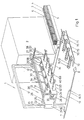
- the storage facility shown in FIG. 1 contains an order-picking device 1 which can be moved along honeycomb shelves 2.
- Fig. 1 only one of these shelves 2 is shown.
- the construction of the honeycomb racks 2 is generally known.
- the stored goods 3 are located in cassettes 4 known per se, only one of which is shown in FIG. 1.
- This cassette 4 is located in one of the end regions of the movement path of the order-picking device 1, from where it can be picked up by the order-picking device 1 and then supplied to one of the shelves 2 in a corresponding compartment.
- two bases 5 and 6 are shown, which stand next to shelf 2.
- On the first base 5 there is the cassette 4 filled with stored goods 3, which is to be supplied in the frame 2.
- An empty cassette 4, which has been removed from the frame 2, can be placed on the second base 6.
- bars, pipes, rails, etc. can be used as storage goods 3.
- the order-picking device 1 moves along the honeycomb racks 2 on rails 7, the end parts of these rails 7 being provided with bumper blocks 8.
- the buffer blocks 8 are opposed to limit switches 9 on the order-picking device 1.
- the order-picking device 1 contains a support frame 10 which extends like a portal between the rails 7. Below are the legs 11 and 12 of the frame 10 in a foot 13 and 14, respectively anchored which parts of a chassis of the order picking device represent.
- the respective foot 13 or 14 is provided with the limit switches 9 and with wheels 15 and 16 which roll on the rails 7.
- the upper parts of the legs 11 and 12 are connected to one another by means of a bar 17.
- a lifting platform 20 extends between the legs 11 and 12.
- This lifting platform 20 has an approximately U-shaped support 21, the legs 22 and 23 of which are hollow.
- the vertical legs 11 and 12 of the support frame 10 pass through the cavities of the legs 22 and 23.
- the legs 11 and 12 and the beam 17 are hollow, so that ropes, rollers and hydraulic lifting cylinders can be accommodated in them, with the aid of which the stage 20 can be moved vertically. By combining the movements in the vertical direction and in the horizontal direction, the lifting platform 20 can reach the desired compartment of the shelves 2.
- the lifting platform 20 also has a cell 25 in or on which the individual devices or devices of the order-picking device 1 are attached.
- This cell 25 contains two frame-shaped cheeks 26 and 27, each of which is fastened to the lifting platform support 21 in the vicinity of the vertical legs 11 and 12.
- the lower front corners of the cheeks 26 and 27 are connected to one another by means of a rigid connecting piece 24.
- the upper vertical sections 28 and .29 of the cheeks 26 and 27 are provided with projecting extensions 31 and 32 which extend in the direction of movement of the order-picking device 1.
- Both the upper sections 28 and 29 and the extensions 31 and 32 of the same are hollow and slotted, so that they can serve as guides for a crane-like device 30 for displacing stored goods 3 in the direction of the movement path of the order-picking device 1.
- the lift is functionally divided into two areas, namely a work platform 35 and a storage goods section 40. These areas extend between the mentioned cheeks 26 and 27 and their length is greater than the length of the longest piece of material stored in the shelves 2.
- the person operating the picking device 1 can be on the work platform 35.
- the actuating elements required for operating the order-picking device 1 can also be located in this area. These are combined in control panels 36 (FIG. 2), one of which is located at least in the respective end region of the work platform 35.
- the floor 65 of the working platform 35 is advantageously designed as a grating. The area of this working platform 35 borders on the lifting platform support 21 in the embodiment of the order-picking device 1 shown in FIG. 1.
- the stored goods section 40 of the lifting platform 20 has a device 45 for handling stored goods 3 and a device 50 for storing stored goods 3.
- the handling device 45 includes the already mentioned crane 30 and a device 41 for moving cassettes 4.
- the crane 30 has a main traverse 33, the end parts of which are mounted in the horizontal parts 28 and 31 and 29 and 32 of the cell 25 and can also be displaced therein.
- Lift cylinders 34 pass through the main cross member 33 and an auxiliary cross member 37 is attached to the piston thereof. From the auxiliary cross member 37, grippers 38 hang down for the individual items 3 to be stored.
- These grippers 38 can be designed as electromagnets, suction elements or simply as hooks for chains or ropes.
- the cassette displacement device 41 contains sets of rollers 43 with a ring distributed along hollow horizontal spacers 42, onto which one of the cassettes 4 can be brought by means of a mechanism 44 known per se. With the aid of the same displacement mechanism 44, the cassette 4 can be removed from such a guideway 43 for the cassettes 4.
- the guideway 43 for the cassettes 4 can also be regarded as one of the components of the storage device 50.
- the storage device 50 also contains a support device 55 for the individual pieces 3 of stored goods and a device 60 for receiving commissions.
- the support device 55 is, as shown in FIG. 1, on the inside of the front wall of the cell 25, while the receiving device 60 is attached to the outside of said front wall.
- These two devices 55 and 60 are designed as storage surfaces which have upwardly directed tines 51.
- These tines 51 form rows which extend parallel to the longitudinal direction of the cell 25 and thus, for example, also to the cross members 33 and 37 and which divide the width of the respective storage surface 55 or 60 into compartments 58 in which the individual commissions or at least the components the same can be kept temporarily.
- the storage surfaces 55 and 60 are formed by support arms 52 protruding from the cell wall, the upper side of which is provided with the prongs 51.
- the intermediate store 70 contains conveyor belts 71 arranged side by side, the outside of which is also provided with tines 51. The distance of these tines 51 from one another is the same as the distance between the tines in the storage area 55 or 60.
- the conveyor belts 71 are mounted on a frame 72, the height of which is selected such that the commissions are easily handled by a standing person can.
- the frame 72 also includes a rail 73 which extends transversely to the direction of movement of the order-picking device 1 and along which a bundling device 75 can be moved.
- the conveyor belts 71 are arranged such that they lie between the support arms 52 of the receiving device 60.
- the commissions that have not yet been bundled can thus simply be placed on the conveyor belts 71, it only being necessary to ensure that the tines 51 of the conveyor belts 71 lie in a row with the tines 51 on the support arms 52. With the help of conveyor belts 71, the respective commission can be brought to the end of the same.
- the person operating the intermediate store 70 can now bind the pieces of material from the commission together with a band from the bundling device 75 as often as required by moving the bundling device 75 along the rail 73.
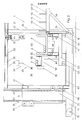
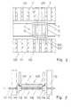
- FIG. 2 shows the order-picking device 1 in a completely lowered position.
- the front posts of the cheeks 26 and 27 are connected to one another at a distance from the bottom region 65 of the cell 25 by means of a further connecting piece 53.
- the inner ends of the support arms 52 are connected to this connecting piece 53, while the outer end parts of the support arms 52 are supported by struts 54 which adjoin the lower connecting piece 24.
- the guideway 43 for the cassette 4 is located directly on the inside of the front wall 53 of the lifting platform cell 25.
- the support device 55 contains rollers 56, the axis of which are approximately perpendicular to the longitudinal direction of the side wall 46.
- the rollers 56 are mounted in brackets 57 and fastened to the side wall 46 with the aid of these. A number of said rollers 56, which are practically at the same height, are distributed over the length of the side wall 46.
- the control panel 36 already mentioned can be attached to the end wall of one or more consoles 57.
- the gripper 38 of the crane 30 above the support device 55 is designed as a hook, the second embodiment of the gripper 38 as an electromagnet also being shown on the right in FIG. 2.
- Cable winches 61 are connected to the main crossbeam 33 of this crane 30, with the aid of which the electromagnets 38 can be lowered to the respective piece of material 3 in order to grip and displace it. From FIG. 2 it can also be seen that the end section of the main crossbeam 33 is connected to carriages 62 which can move inside the upper sections 28 and 31 or 29 and 32 of the cell 25.
- the extension pieces 31 and 32 protrude so far that the crane 30 can also move over the entire length of the receiving device 60, in order to be able to place 60 pieces for a commission even in the most distant compartment 58 of this device.
- the guideway 43 and the support device 55 rest on a plate 63 which is supported on the bottom 65 of the cell 25 by pressure cells 64.
- the control panel 36 is provided with a corresponding display instrument (not shown) from which the weight of the material pieces 3 located on the guideway 43 and the support device 55 can be read.
- FIG. 2 also shows rollers 66 which are located inside the support legs 22 and 23 and which ensure easy guidance of the lifting platform 20 along the legs 11 and 12 of the support frame 10.
- the support device 55 is actually located in the area of the lifting platform 20 which is intended for the person operating the picking device 1.
- the support device 55 can be arranged above the guideway 43, as shown in FIG. 3.
- a support device arranged at this point would, however, hinder access to the inside of the cassette 4 by the crane 30. Therefore, the support device 55 is designed to be horizontally displaceable, so that it extends forward from the region of the guideway 43, ie. H. out of the interior of the cell 25. This can be accomplished with the aid of horizontal hollow rails 68 which are fastened to the inside of the cheeks 26 and 27 at a corresponding height above the floor 65.
- the displacement of the support device 55 can be carried out by hand. In its forward position, the support device is in no way in the way because the crane 30 is above it and because, if necessary, this device 55 can also be moved relative to the compartments 58 defined by the tines 51.
- the device 60 for the temporary reception of unbundled commissions can be removably attached to the cell 25 of the order-picking device 1.
- the device 60 can be fastened, for example, with the aid of screws 69.
- This version of the order-picking device can be of particular advantage if the size of the compartments 58 in the receiving device 60 is to be changed frequently.
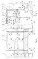
- FIGS. 4 and 5 Another embodiment of the present The system is shown in FIGS. 4 and 5.
- the order-picking device 1 has a work platform 35, the height of which can be set independently of the height of the storage goods section 40.
- the support frame 10 has two frame-shaped parts 96 and 97, which extend perpendicular to the direction of movement of the operating device 1. These frames 96 and 97 are connected at the bottom to the frame feet 13 and 14 and at the top they are connected to one another by means of ties 98.
- the guide track 43 for a cassette 4 is located between the frames 96 and 97, the receiving device 60 together with the extensions 31 projecting from the front of the lift cell.
- the guideway 43 and the receiving device 60 can be moved with the aid of ropes 76 which are guided over deflection rollers 77 which are also located in the supporting frame 10.
- the force required for this is generated either by a cable winch 78 (FIG. 5) or by hydraulic cylinders 79 in the carrier legs 11 and 12.
- the working platform 35 is located on the rear outer side of the support frame 10 and it has the floor 65, to which a railing 82 connects.
- the inside of the platform 35 is provided with a vertically extending support part 83, via which the platform 35 is connected to the support frame 10.
- the platform 35 is provided with rollers 84 and 85, which can be moved in a guided manner on the legs 11 and 12 of the frame 10.
- a drive device 81 is provided which enables the platform 35 to be brought to the desired height. Such drive devices are generally known and therefore this drive device 81 need not be described in more detail here. 5, the platform 351 is also shown in one of its upper layers.
- the platform 35 is provided with a trough 86, in which the individual pieces 3 of stored goods can be pulled in by hand from the honeycomb compartments of the frames 2 and from which the individual pieces 3 can be transferred into the receiving device 60 with the aid of the crane 30. Since it is expected that only individual items will be transported with the aid of the platform 35, the drive 81 of the platform 35 can be designed in such a way that it moves up and down relatively quickly. This saves time in comparison with the case in which, because of individual pieces of stored goods, the stored goods section 40 together with the handling device 45 assigned to it has to be set in motion. The independently movable platform 35 thus enables greater efficiency in the work of the storage facility.
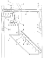
- the measure shown in FIG. 6 leads to a further improvement in the degree of utilization of the storage device.
- the commissioning device 1 has the frame 10, in which the platform 35 and the storage goods section 40 form a whole.
- a staircase 87 which makes it possible to enter or leave the platform 35 and thus also the entire lifting platform at every height adjustment thereof.
- This staircase 87 is connected to the floor 65 of the platform 35 by means of joints 88.
- the cheeks 89 of the stairs 87 are designed as trusses.
- the tread 90 is also articulated to the slope 91 of the respective step 92 below.
- the lower end of the stairs 92 is provided with wheels 93 which can roll on the floor of the warehouse.
- the staircase 87 thus offers the possibility of immediately removing individual items of stored goods from the platform 35 instead of waiting until the entire order-picking device 1 reaches its end position. The same applies in the event that one or more individual items of stored goods are to be stored in the racks.
- the storage goods section 40 of such an order-picking device 1 is provided with the guideway 43 for a cassette 4, which is also provided with the pull-out and pull-in device 44 for handling the cassettes.
- a cassette 4 which is also provided with the pull-out and pull-in device 44 for handling the cassettes.
- On the side wall 46 of the guideway 43 several obliquely extending arms 95 are attached one above the other, which form compartments for the individual items of stored goods.
- Several types of individual pieces can be temporarily stored here. With the help of the crane 30, these individual pieces can also be transferred into the receiving device 60.
- This storage facility is designed in such a way that the desired commissions automatically, i. H. controlled by a computer, can be put together. Such a control works extremely quickly, so that the conditions for a very quick commissioning are given.
- these requirements cannot be sufficiently used in the system described above, because the movements of the order picking device and its components can only be slow due to the large mass of the same.
- the following design of this system eliminates this disadvantage.
- the storage system shown in FIG. 7 contains the order-picking device 1, which can be moved along honeycomb racks 2. Only one of these shelves 2 is shown in FIG. 7, although it should also be said that only part of the rack frame 2 is shown in FIG. 7. Because the honeycomb shelf 2 is usually much longer than shown.
- the stored goods 3 are located in cassettes 4 known per se, of which only three cassettes 4 are shown in FIG. 7. Two of these cassettes 4 are located in the picking device 1, while the third cassette 4 is accommodated in the frame 2. There is only one cassette 4 in each compartment of the frame 2. For example, bars, tubes, rails, etc. can be used as storage goods 3.
- the order-picking device 1 moves along the honeycomb rack 2 on rollers 19 and rails 7.
- the order-picking device 1 contains a support frame 100 which is located between the rails 7 extends.
- This support frame 100 has two portal-like sections 101 and 102 which extend between the rails 7 and which are parallel to one another. Each of these portals 101 and 102 has vertically extending legs 11 and 12 which are connected to one another by a bar 17.
- the portals 101 and 102 are connected at the top by means of a yoke 103, the longitudinal direction of which practically coincides with the direction of movement of the order-picking device 1.
- Below the legs 11 and 12 of the frame 100 are anchored in a foot 13 in which the wheels 19 are located.
- the respective portals 101 and 102 are each assigned a hoist 20 and 201 which extend between the legs 11 and 12 of the relevant portals 101 and 102.
- the respective portal 101 or 102 is provided with drive means (not shown) known per se for the lifting platforms 20 and 201, so that one lifting platform can move independently of the other lifting platform in the vertical direction, ie. H. can move along the legs 11 and 12.
- Fig. 7 the left lift 20 is shown in its lowest position.
- the lifting platform 201 shown on the right in FIG. 7 is shown in one of its upper positions, where it faces one of the compartments 105 of the frame 2.
- the lifting platforms 20 and 201 have an approximately U-shaped and horizontally extending support 21, the legs 22 of which are hollow.
- the vertical legs 11 and 12 of the support frame 100 pass through the cavities in these legs 22.
- the legs 11 and 12, the beams 17 and the yokes 103 are hollow, so that ropes, rollers and hydraulic lifting cylinders can be accommodated in them, with the aid of which the platforms 20 and 201 can be moved in the vertical direction.
- the respective lifting platform 20 or 201 has a cell 25, in or on which the individual devices or devices thereof are attached.
- the cell 25 contains two frame-shaped cheeks 26. That vertical section 106 of the frame 26 which is in the vicinity of the respective leg 22 is fastened to the latter, so that the frame 26 can be moved with the carrier 21 in the vertical direction.
- the lower horizontal sections of the frames 26 are connected to one another by means of a floor 65 of the lifting platform 20.
- the upper horizontal sections 28 of the cheeks 26 are provided with protruding extensions 31 which extend in the direction of movement of the order-picking device 1.
- Both the upper sections 28 of the respective frame 26 and the extensions 31 thereof are hollow and slotted, so that they can serve as guides for a crane-like device 30 for displacing stored goods 3 in the direction of the path of movement of the picking device 1.
- the respective lifting platform 20 is functionally divided into two areas, namely a work platform 35 and a storage goods section 40. These areas extend between the mentioned cheeks 26 and the length of these areas is greater than the length of the longest piece of material 3 stored in the shelves 2 .
- the person operating the picking device 1 can be on the work platform 35.
- the actuating elements required for operating the order-picking device 1 can also be located in this area. These are combined in control panels (not shown), one of which is located at least in the respective end region of the work platform 35.
- the floor 65 of the working platform 35 is advantageously designed as a grating.
- a device 41 for handling cassettes 4 which can be of a type known per se. It has rollers on which the respective cassette 4 can move.
- the device 41 also contains means for pulling out a cassette 4 and for inserting the same.
- the guideway 41 for the cassette 4 is located directly on the inside of the front wall of the lift cell 25.
- the stored goods section 40 of the lifting platform 20 has a device for handling stored goods 3 and a device 50 for storing stored goods 3.
- the handling device includes the crane 30 already mentioned.
- the storage device 50 contains arms 52 for receiving commissions 3 which are attached to the outside of the cell 25 of the lifting platform 20. These arms 52 have storage surfaces which are provided with upwardly directed tines 51. These tines 51 form rows which extend parallel to the longitudinal direction of the cell 25 and which divide the width of the respective storage area into compartments 58 in which the individual commissions 3 or at least components thereof can be temporarily stored.
- the rack frame 2 has posts 110 which form rows, as can be seen clearly from FIG. 8. These posts 110 are connected to one another in the horizontal direction in a manner known per se in such a way that they form the skeleton of an approximately rectangular storage rack 2. Between the posts 110 of adjacent rows of posts there are floors 111 arranged one above the other, on which the respective cassette 4 rests when it is in one of the compartments 105. A compartment 105 thus comprises the respective floor 111 and the cavity above, in which a cassette 4 can be located.
- FIG. 9 shows the essential parts of a shelf compartment 105.
- the end parts of shafts 112 are supported on the posts 110.
- rollers 113 In the area of the end part of the respective shaft 112 there are rollers 113 with a ring 114, the The collar 114 is closer to the post 110 than the cylindrical portion 115 of the respective roller 113.
- the cassette 4 rests on the cylindrical portion 115 of the rollers 113, which are located on successive and horizontally arranged shafts 112.
- the collar 114 prevents the Cassette 4 comes into contact with the post 110. Because this would result in a malfunction of the operation of the storage facility.
- the cassette 4 itself has standing U-pieces 116, which are distributed over the entire length of the cassette 4.
- the lower corner parts of the U-pieces 116 are connected by means of angle iron 117, which extend over the entire length of the cassette 4.
- a lock 125 is implemented in the central area of the frame 2. This lock 125 arises from the fact that the compartments 105 are left out in a specific area of the shelf 2.
- the correspondingly shortened posts 110 are supported on a horizontal support 126.
- the lock 125 there are known devices (not shown) on which the cassettes 4 can be placed if they are to be introduced into or removed from the bearing. This can be the case if empty cassettes 4 are to be refilled or the like.
- the lock 125 in FIG. 7 is made wider than will be the case in practice. Because such a wide lock 125 makes it possible to present the individual parts of the lifting platform 20 in a more manageable manner.
- the width of the lock 125 should actually only correspond to the width of the work platforms 35 of the two lifting platforms 20 and 201 in order to achieve the largest possible volume of the frame 2.
- one of the lifting platforms 20 or 201 moves in the vertical direction in such a way that it reaches the height of the compartment 105 from which the required pieces of material 3 are to be removed.
- the order-picking device 1 also moves towards said compartment 105 in the horizontal direction, if necessary.
- the cassette 4 is pulled out of the compartment 105 and it then rests in the lifting platform on the sliding device 41.
- the operator can use the crane 30 to store the required pieces 3 in the required number 3 in the individual compartments 58 of the device 50. Such work takes a certain amount of time.
- the order picker 1 and the other of the lifting platforms can move so that these other lift f another bearing ach reaches 105 to be removed from the material 3 and in which a cassette 4 is located in this lift is to be deposited.
- cassettes 4 can be loaded or unloaded per unit of time and possibly also brought in through locks than was the case with the known storage facilities.
Description
Die vorliegende Erfindung betrifft eine Lageranlage mit einem Kommissioniergerät, das entlang von Wabenregalen bewegbar ist und eine Hebebühne aufweist, wobei diese Hebebühne eine Arbeitsplattform und einen Lagergutsabschnitt aufweist, der eine Ablageeinrichtung für das Lagergut sowie eine Einrichtung zur Handhabung von Lagergut enthält (siehe z. B. EP-A-116152).The present invention relates to a storage system with an order-picking device which can be moved along honeycomb racks and has a lifting platform, this lifting platform having a working platform and a storage item section which contains a storage device for the stored goods and a device for handling stored goods (see e.g. EP-A-116152).
Die Wabenregale einer bekannten Lagereinrichtung dieser Art sind so ausgeführt, dass sie zur Aufnahme einzelner Stücke von Lagergut eingerichtet sind. Die Einrichtung zur Handhabung von Lagergut muss daher derart sein, dass sie die einzelnen Stücke von Lagergut ergreifen kann, um sie in das Innere des Kommissioniergerätes einzuziehen. Im Kommissioniergerät ist eine praktisch glatte und durch auskragende Tragarme gebildete Ablagefläche vorhanden, auf der die ausgewählten Stücke von Lagergut gesammelt werden. Nach der Beendigung einer Kommission werden die Materialstücke derselben mit Hilfe einer Bündelungseinrichtung zusammengebunden und mit Hilfe von in den Tragarmen integrierten Rollen gegen das freie Ende dieser Tragarme transportiert. Spätestens, wenn es keinen Platz mehr auf den Tragarmen gibt, fährt das Kommissioniergerät zu einem Ablagetisch, wo alle Kommissionen abgesetzt werden.The honeycomb racks of a known storage device of this type are designed in such a way that they are designed to accommodate individual pieces of storage goods. The device for handling stored goods must therefore be such that it can grip the individual pieces of stored goods in order to draw them into the interior of the picking device. The picking device has a practically smooth storage surface formed by cantilevered support arms, on which the selected pieces of stored goods are collected. After the completion of a commission, the material pieces of the same are bound together with the aid of a bundling device and transported against the free end of these support arms by means of rollers integrated in the support arms. At the latest when there is no more space on the support arms, the picking device moves to a storage table, where all the commissions are placed.
Wenn bei dieser bekannten Anlage mehrere Kommissionen zugleich gemacht werden sollen, dann müssen die.Materialstücke der Kommissionen sofort nach Beendigung derselben zusammegebunden werden, denn sonst droht die Gefahr, dass. sich die Materialstücke einzelner Kommissionen auf der Ablagefläche vermischen. Die sofortige Bündelung der Materialstücke setzt voraus, dass die Hebebühne mit einer Bündelungseinrichtung versehen ist. Das sofortige Bündeln ist in mancher Hinsicht nachteilig, z. B. wenn am Ablagetisch ungebündelte Kommissionen vorhanden sein sollen. Ausserdem steht das Kommissioniergerät still, wenn die Bedienungsperson mit der Bündelung der Kommissionen beschäftigt ist. Die Arbeitsweise der bekannten Anlage kann wegen der Notwendigkeit der Bündelung der Kommissionen bereits im Kommissioniergerät nicht voll automatisiert werden.If several commissions are to be made at the same time in this known system, then the material pieces of the commissions must be bound together immediately after the same, because otherwise there is a risk that the material pieces of individual commissions mix on the storage surface. The immediate bundling of the pieces of material requires that the lift is equipped with a bundling device. Immediate bundling is disadvantageous in some respects, e.g. B. if unbundled commissions are to be present at the filing table. In addition, the picking device is at a standstill when the operator is busy bundling the commissions. The operation of the known system can not be fully automated in the picking device due to the need to bundle the commissions.
Die Hebebühne dieser bekannten Anlage muss nicht nur mit der Einzugseinrichtung für die einzelnen Materialstücke sondern auch mit der verschiebbar angeordneten Bündelungseinrichtung versehen sein, was unter Umständen Platzprobleme zur Folge haben kann. Diese Probleme würden weiter anwachsen, wenn eine solche Bühne noch mit einer Verschiebeeinrichtung für eine Kassette ausgerüstet sein sollte, in der das Lagergut abgelagert ist. Die Integration der Rollen in die Tragarme und deren Antrieb stellen zudem eine verhältnismässig komplizierte technische Lösung dar.The lifting platform of this known system must not only be provided with the feed device for the individual pieces of material but also with the displaceably arranged bundling device, which under certain circumstances can result in space problems. These problems would increase if such a platform were to be equipped with a moving device for a cassette in which the stored goods are stored. The integration of the rollers in the support arms and their drive also represent a relatively complicated technical solution.
Die Aufgabe der vorliegenden Erfindung ist, eine Lageranlage zu schaffen, welche die genannten Nachteile nicht aufweist.The object of the present invention is to provide a storage facility which does not have the disadvantages mentioned.
Diese Aufgabe wird bei der Lageranlage der eingangs genannten Art erfindungsgemäss so gelöst, wie dies im kennzeichnenden Teil des Anspruchs 1 definiert ist.This object is achieved according to the invention in the storage system of the type mentioned at the outset, as defined in the characterizing part of
Nachstehend werden Ausführungsbeispiele der vorliegenden Erfindung anhand der beiliegenden Zeichnungen näher erläutert. Es zeigt :
- Fig. 1 perspektivisch die vorliegende Lageranlage mit einem Kommissioniergerät,
- Fig. 2 in einer Seitenansicht eine zweite Ausführungsform des Kommissioniergerätes der Anlage nach Fig. 1,
- Fig. 3 in einer Seitenansicht eine dritte Ausführungsform des Kommissioniergerätes der Anlage nach Fig. 1,
- Fig. 4 in einer Frontansicht eine vierte Ausführungsform des Kommissioniergerätes der Anlage nach Fig. 1,
- Fig. 5 in einer Seitenansicht das Gerät aus Fig. 1,
- Fig. 6 in einer Seitenansicht eine fünfte Ausführungsform des Kommissioniergerätes der Anlage nach .Fig. 1,
- Fig. 7 in einer Seitenansicht die vorliegende Lageranlage,
- Fig. 8 in Draufsicht eine weitere Ausführungsform der vorliegenden Lageranlage und
- Fig. 9 in Frontansicht ein Detail aus einem Gestell der vorliegenden Lageranlage.
- 1 is a perspective view of the present storage system with an order picking device,
- 2 shows a side view of a second embodiment of the picking device of the system according to FIG. 1,
- 3 is a side view of a third embodiment of the picking device of the system according to FIG. 1,
- 4 is a front view of a fourth embodiment of the picking device of the system according to FIG. 1,
- 5 is a side view of the device of FIG. 1,
- Fig. 6 in a side view of a fifth embodiment of the order picking system according to .Fig. 1,
- 7 is a side view of the present storage facility,
- Fig. 8 in plan view a further embodiment of the present storage facility and
- Fig. 9 in front view a detail from a frame of the present storage facility.
Die in Fig. 1 dargestellte Lageranlage enthält ein Kommissioniergerät 1, das entlang von Wabenregalen 2 bewegt werden kann. In Fig. 1 ist nur eines dieser Regale 2 dargestellt. Die Konstruktion der Wabenregale 2 ist allgemein bekannt. Das Lagergut 3 befindet sich in an sich bekannten Kassetten 4, von welchen nur eine in Fig. 1 dargestellt ist. Diese Kassette 4 befindet sich in einem der Endbereiche der Bewegungsbahn des Kommissioniergerätes 1, von wo sie durch das Kommissioniergerät 1 aufgenommen und dann in einem entsprechenden Fach eines der Regale 2 versorgt werden kann. In diesem Endbereich sind zwei Sockel 5 und 6 dargestellt, die neben dem Regal 2 stehen. Auf dem ersten Sockel 5 befindet sich die mit Lagergut 3 gefüllte Kassette 4, die im Gestell 2 zu versorgen ist. Auf dem zweiten Sockel 6 kann eine leere Kassette 4 abgestellt werden, die dem Gestell 2 entnommen worden ist. In einem Fach des Gestelles 2 befindet sich jeweils eine Kassette 4. Als Lagergut 3 kommen beispielsweise Stangen, Rohre, Schienen usw. in Frage. Das Kommissioniergerät 1 bewegt sich entlang den Wabenregalen 2 auf Schienen 7, wobei die Endpartien dieser Schienen 7 mit Prellböcken 8 versehen sind. Den Prellböcken 8 stehen Endschalter 9 am Kommissioniergerät 1 gegenüber.The storage facility shown in FIG. 1 contains an order-
Das Kommissioniergerät 1 enthält ein Traggestell 10, das sich portalartig zwischen den Schienen 7 erstreckt. Unten sind die Schenkel 11 und 12 des Rahmens 10 in je einem Fuss 13 und 14 verankert, welche Bestandteile eines Fahrgestells des Kommissioniergerätes darstellen. Der jeweilige Fuss 13 bzw. 14 ist mit den Endschaltern 9 sowie mit Rädern 15 und 16 versehen, die auf den Schienen 7 abrollen. Die oberen Partien der Schenkel 11 und 12 sind mit Hilfe eines Balkens 17 untereinander verbunden.The order-
Zwischen den Schenkeln 11 und 12 erstreckt sich eine Hebebühne 20. Diese Hebebühne 20 weist einen etwa U-förmigen Träger 21 auf, dessen Schenkel 22 und 23 hohl sind. Durch die Hohlräume der Schenkel 22 und 23 gehen die vertikalen Schenkel 11 und 12 des Traggestelles 10 hindurch. Die Schenkel 11 und 12 und der Balken 17 sind hohl ausgebildet, so dass in diesen Seile, Rollen und hydraulische Hubzylinder untergebracht sein können, mit deren Hilfe die Bühne 20 vertikal bewegt werden kann. Durch die Kombination der Bewegungen in vertikaler Richtung und in horizontaler Richtung, kann die Hebebühne 20 das jeweils gewünschte Fach der Regale 2 erreichen.A
Die Hebebühne 20 weist ferner eine Zelle 25 auf, in der oder an der die einzelnen Ein- bzw. Vorrichtungen des Kommissioniergerätes 1 angebracht sind. Diese Zelle 25 enthält zwei rahmenförmige Wangen 26 und 27, von welchen jede in der Nähe der vertikalen Schenkel 11 und 12 am Hebebühnenträger 21 befestigt ist. Die unteren vorderen Ecken der Wangen 26 und 27 sind mit Hilfe eines steifen Verbindungsstückes 24 miteinander verbunden. Die oberen vertikalen Abschnitte 28 und .29 der Wangen 26 und 27 sind mit vorstehenden Verlängerungen 31 und 32 versehen, die sich in der Bewegungsrichtung des Kommissioniergerätes 1 erstrecken. Sowohl die oberen Abschnitte 28 und 29 als auch die Verlängerungen 31 und 32 derselben sind hohl ausgeführt und geschlitzt, so dass sie als Führungen für eine kranartige Vorrichtung 30 zum Versetzen von Lagergut 3 in der Richtung der Bewegungsbahn des Kommissioniergerätes 1 dienen können.The
Die Hebebühne ist funktionsmässig in zwei Bereiche unterteilt, nämlich in eine Arbeitsplattform 35 und in einen Lagergutsabschnitt 40. Diese Bereiche erstrecken sich zwischen den genannten Wangen 26 und 27 und deren Länge ist grösser als die Länge des längsten in den Regalen 2 gelagerten Materialstücks.The lift is functionally divided into two areas, namely a
Auf der Arbeitsplattform 35 kann sich die das Kommissioniergerät 1 bedienende Person aufhalten. In diesem Bereich können sich auch die zur Bedienung des Kommissioniergerätes 1 erforderlichen Betätigungselemente befinden. Diese sind in Steuerpulten 36 (Fig. 2) zusammengefasst, von welchen sich je eines wenigstens im jeweiligen Endbereich der Arbeitsplattform 35 befindet. Der Boden 65 der Arbeitsplattform 35 ist vorteilhaft als ein Gitterrost ausgeführt. Der Bereich dieser Arbeitsplattform 35 grenzt bei der in Fig. 1 dargestellten Ausführungsform des Kommissioniergerätes 1 am Hebebbühnenträger 21 an.The person operating the
Der Lagergutsabschnitt 40 der Hebebühne 20 weist eine Einrichtung 45 zur Handhabung von Lagergut 3 sowie eine Einrichtung 50 zum Ablegen von Lagergut 3 auf. Zur Handhabungseinrichtung 45 gehört der bereits erwähnte Kran 30 sowie eine Vorrichtung 41 zum Verschieben von Kassetten 4.The stored
Der Kran 30 weist eine Haupttraverse 33 auf, deren Endpartien in den horizontalen Partien 28 und 31 sowie 29 und 32 der Zelle 25 gelagert und in diesen auch verschiebbar sind. Durch die Haupttraverse 33 gehen Hubzylinder 34 hindurch und an den Kolben dieser ist eine Hilfstraverse 37 befestigt. Von der Hilfstraverse 37 hängen Greifer 38 für die einzelnen Lagergutsstücke 3 herab. Diese Greifer 38 können als Elektromagnete, Saugelemente oder einfach als Haken für Ketten oder Seile ausgebildet sein.The
Wie beispielsweise aus Fig. 2 ersichtlich ist, enthält die Kassetten-Verschiebevorrichtung 41 entlang von hohlen horizontalen Distanzstücken 42 verteilte Sätze von Rollen 43 mit Kranz, auf welche eine der Kassetten 4 mit Hilfe eines an sich bekannten Mechanismus 44 gebracht werden kann. Mit Hilfe desselben Verschiebemechanismus 44 kann die Kassette 4 aus einer solchen Führungsbahn 43 für die Kassetten 4 entfernt werden.As can be seen, for example, from FIG. 2, the
Die Führungsbahn 43 für die Kassetten 4 kann auch als einer der Bestandteile der Ablageeinrichtung 50 betrachtet werden. Die Ablageeinrichtung 50 enthält ferner eine Stützvorrichtung 55 für die einzelnen Stücke 3 von Lagergut sowie eine Vorrichtung 60 zur Aufnahme von Kommisionen.The
Die Stützvorrichtung 55 befindet sich, gemäss Fig. 1, an der Innenseite der Frontwand der Zelle 25, während die Aufnahmevorrichtung 60 an der Aussenseite der genannten Frontwand angebracht ist. Diese beiden Vorrichtungen 55 und 60 sind als Ablageflächen ausgeführt, welche aufwärts gerichtete Zinken 51 aufweisen. Diese Zinken 51 bilden Reihen, welche sich parallel zur Längsrichtung der Zelle 25 und somit beispielsweise auch zu den Traversen 33 und 37 erstrecken und welche die Breite der jeweiligen Ablagefläche 55 bzw. 60 in Abteile 58 unterteilen, in welchen die einzelnen Kommissionen oder wenigstens die Bestandteile derselben vorübergehend aufbewahrt werden können. Wie aus Fig. 1 weiter ersichtlich ist, sind die Ablageflächen 55 und 60 durch von der Zellenwand abstehende Tragarme 52 gebildet, deren Oberseite mit den Zinken 51 versehen ist.The
An einem Ende der Bewegungsbahn des Kommissioniergerätes 1 befindet sich ein Zwischenlager 70 für die im Kommissioniergerät 1 erstellten Kommissionen. Hier werden die Kommissionen gebündelt und sie können hier aüch gelagert werden, bis sie aus dem Lagerraum wegtransportiert werden. Das Zwischenlager 70 enthält nebeneinander angeordnete Förderbänder 71, deren Aussenseite ebenfalls mit Zinken 51 versehen ist. Der Abstand dieser Zinken 51 voneinander ist derselbe wie der Zinkenabstand bei den Ablagefläche 55 bzw. 60. Die Fördebänder 71 sind auf einem Rahmen 72 montiert, dessen Höhe so gewählt ist, dass die Kommissionen durch eine stehende Person ohne Mühe gehandhabt werden können. Zum Rahmen 72 gehört auch eine Schiene 73, die sich quer zur Bewegungsrichtung des Kommissioniergerätes 1 erstreckt und entlang welcher eine Bündelungsvorrichtung 75 bewegt werden kann. Die Förderbänder 71 sind derart angeordnet, dass sie zwischen den Tragarmen 52 der Aufnahmevorrichtung 60 liegen. Die Kommissionen, die noch nicht gebündelt sind, können somit auf die Förderbänder 71 einfach abgesetzt werden, wobei nur dafür zu sorgen ist, dass die Zinken 51 der Förderbänder 71 in einer Reihe mit den Zinken 51 auf den Tragarmen 52 liegen. Mit Hilfe der Förderbänder 71 kann die jeweilige Kommission bis ans Ende derselben gebracht werden. Die das Zwischenlager 70 bedienende Person kann nun so oft wie erforderlich die Materialstücke der Kommission mit einem Band aus der Bündelvorrichtung 75 zusammenbinden, indem sie die Bündelvorrichtung 75 entlang der Schiene 73 bewegt.At one end of the movement path of the
In Fig. 2 ist das Kommissioniergerät 1 in vollständig abgesenkter Lage dargestellt. Die vorderen Pfosten der Wangen 26 und 27 sind mit Hilfe eines weiteren Verbindungsstückes 53 in einem Abstand vom Bodenbereich 65 der Zelle 25 miteinander verbunden. An dieses Verbindungsstück 53 sind die inneren Enden der Tragarme 52 angeschlossen, während die äusseren Endpartien der Tragarme 52 durch Streben 54 abgestützt sind, die sich an das untere Verbindungsstück 24 anschliessen.2 shows the order-picking
Bei diesem Kommissioniergerät 1 befindet sich die Führungsbahn 43 für die Kassette 4 unmittelbar an der Innenseite der Vorderwand 53 der Hebebünnenzelle 25. An der Seitenwand 46 dieser Führungsbahn 43 befindet sich erst die Stützvorrichtung 55 für die einzelnen Stücke 3 von Lagergut. Die Stützvorrichtung 55 enthält Rollen 56, deren Achse etwa senkrecht zur Längsrichtung der Seitenwand 46 stehen. Die Rollen 56 sind in Konsolen 57 gelagert und mit Hilfe dieser an der Seitenwand 46 befestigt. Ueber die Länge der Seitenwand 46 ist eine Anzahl der genannten Rollen 56 verteilt, die sich praktisch auf derselben Höhe befinden. An der Stirnwand einer oder mehreren Konsolen 57 kann das bereits erwähnte Steuerpult 36 befestigt sein. Man kann einzelne Stücke 3 von Lagergut aus den sich im Regal 2 befindlichen Kassetten 4 von Hand herausziehen, wenn das Gewicht der Materialstücke 3 derart ist, dass sie sich von Hand handhaben lassen, und auf der Stützvorrichtung 55 vorübergehend ablegen. Dann kann man diese Stücke mit Hilfe des Kranes 30 in einen der Abteile der Aufnahmevorrichtung 60 versetzen.In this order-picking
Der Greifer 38 des Kranes 30 über der Stützvorrichtung 55 ist als ein Haken ausgeführt, wobei in dieser Fig. 2 rechts auch die zweite Ausführungsmöglichkeit des Greifers 38 als Elektromagnet gezeigt ist. An die Haupttraverse 33 dieses Kranes 30 sind Seilwinden 61 angeschlossen, mit deren Hilfe die Elektromagnete 38 bis zum jeweiligen Materialstück 3 herabgesenkt werden können, um dieses zu ergreifen und zu versetzen. Aus Fig. 2 ist ferner ersichtlich, dass die Endpartie der Haupttraverse 33 an Wagen 62 angeschlossen sind, die sich im Inneren der oberen Partien 28 und 31 bzw. 29 und 32 der Zelle 25 bewegen können. Die Verlängerungsstücke 31 und 32 kragen dabei so weit aus, dass sich der Kran 30 unter anderem auch über die ganze Länge der Aufnahmevorrichtung 60 bewegen kann, um sogar im entferntesten Abteil 58 dieser Vorrichtung 60 Stücke für eine Kommission ablegen zu können.The
Die Führungsbahn 43 und die Stützvorrichtung 55 ruhen auf einer Platte 63, die über Druckmessdosen 64 auf dem Boden 65 der Zelle 25 abgestützt ist. Der Steuerpult 36 ist mit einem entsprechenden Anzeigeinstrument (nicht dargestellt) versehen, von dem das Gewicht der sich auf der Führungsbahn 43 und der Stützvorrichtung 55 befindlichen Materialstücke 3 abgelesen werden können.The
Fig. 2 zeigt auch Rollen 66, die sich im Inneren der Trägerschenkel 22 und 23 befinden und die für eine leichte Führung der Hebebühne 20 entlang den Schenkeln 11 und 12 des Traggestelles 10 sorgen. Diesem Zweck dienen auch Führungsvorsprünge 67 auf den Schmalseiten der Gestellschenkel 11 und 12, die die Rollen 66 entlang den Schenkeln 11 und 12 führen.FIG. 2 also shows
Beim Kommissioniergerät nach Fig. 2 kann es unter Umständen nachteilig sein, dass die Stützvorrichtung 55 sich eigentlich in jenem Bereich der Hebebühne 20 befindet, der für die das Kommissioniergerät 1 bedienende Person bestimmt ist. Um in diesem Bereich mehr Platz zu gewinnen, kann die Stützvorrichtung 55 oberhalb der Führungsbahn 43 angeordnet sein, wie dies in Fig. 3 dargestellt ist. Eine an dieser Stelle fest angeordnete Stützvorrichtung würde jedoch den Zugang zum Inneren der Kassette 4 durch den Kran 30 behindern. Deswegen ist die Stützvorrichtung 55 horizontal verschiebbar ausgeführt, so dass sie sich aus dem Bereich der Führungsbahn 43 nach vorne, d. h. aus dem Inneren der Zelle 25 heraus, herausfahren lässt. Dies kann mit Hilfe von horizontalen Hohlschienen 68 bewerkstelligt werden, die an der Innenseite der Wangen 26 und 27 in einer entsprechenden Höhe über dem Boden 65 befestigt sind. Die Verschiebung der Stützvorrichtung 55 kann von Hand durchgeführt werden. In ihrer vorderen Lage steht die Stützvorrichtung keineswegs im Wege, weil der Kran 30 sich oberhalb dieser befindet und weil, wenn erforderlich, sich diese Vorrichtung 55 auch gegenüber den durch die Zinken 51 definierten Abteilen 58 verschieben lässt.2 it may be disadvantageous that the
Ferner zeigt Fig. 3, dass die Vorrichtung 60 für die vorübergehende Aufnahme ungebündelter Kommissionen an der Zelle 25 des Kommissioniergerätes 1 wegnehmbar befestigt sein kann. Die Befestigung der Vorrichtung 60 kann beispielsweise mit Hilfe von Schrauben 69 durchgeführt werden. Diese Ausführung des Kommissioniergerätes kann dann von besonderem Vortiel sein, wenn die Grösse der Abteile 58 in der Aufnahmevorrichtung 60 oft geändert werden soll.3 also shows that the
Eine weitere Ausführungsform der vorliegenden Anlage ist in den Fig. 4 und 5 dargestellt. Bei dieser Anlage weist das Kommissioniergerät 1 eine Arbeitsplattform 35 auf, deren Höhe unabhängig von der Höhe des Lagergutsabschnittes 40 einstellbar ist. Das Traggestell 10 besitzt zwei rahmenförmige Teile 96 und 97, die sich senkrecht zur Bewegungsrichtung des Bedienungsgerätes 1 erstrecken. Diese Rahmen 96 und 97 sind unten mit den Gestellfüssen 13 und 14 verbunden und oben sind sie mit Hilfe von Bindern 98 miteinander verbunden. Zwischen den Rahmen 96 und 97 befindet sich die Führungsbahn 43 für eine Kassette 4, wobei die Aufnahmevorrichtung 60 samt den Verlängerungen 31 von der Frontseite der Hebebühnezelle abstehen. Die Führungsbahn 43 und die Aufnahmevorrichtung 60 können mit Hilfe von Seilen 76 bewegt werden, die über sich ebenfalls im Traggestellt 10 befindliche Umlenkrollen 77 geführt werden. Die dazu notwendige Kraft wird entweder durch eine Seilwinde 78 (Fig. 5) oder durch Hydraulikzylinder 79 in den Trägerschenkeln 11 und 12 erzeugt.Another embodiment of the present The system is shown in FIGS. 4 and 5. In this system, the order-picking
Die Arbeitsplattform 35 befindet sich an der hinteren äusseren Seite des Traggestelles 10 und sie weist den Boden 65 auf, an den sich ein Geländer 82 anschliesst. Die Innenseite der Plattform 35 ist mit einem vertikal verlaufenden Tragteil 83 versehen, über welchen die Plattform 35 am Traggestell 10 angeschlossen ist. Die Plattform 35 ist mit Rollen 84 und 85 versehen, die an den Schenkeln 11 bzw. 12 des Rahmens 10 geführt bewegbar sind. Es ist eine Antriebsvorrichtung 81 vorgesehen, die ermöglicht, die Plattform 35 in die gewünschte Höhe zu bringen. Solche Antriebsvorrichtungen sind allgemein bekannt und deswegen braucht diese Antriebsvorrichtung 81 hier nicht näher dargelegt zu werden. In Fig. 5 ist die Plattform 351 auch in einer ihrer oberen Lagen dargestellt.The working
Die Plattform 35 ist mit einem Trog 86 versehen, in welchen die einzelnen Stücke 3 von Lagergut aus den Wabenfächern der Gestelle 2 von Hand eingezogen werden können und aus welchem die Einzelstücke 3 in die Aufnahmevorrichtung 60 mit Hilfe des Krans 30 übertragen werden können. Da man damit rechnet, dass mit Hilfe der Plattform 35 nur Einzelstücke befördert werden, kann man den Antrieb 81 der Plattform 35 so auslegen, dass sich diese verhältnismässig schnell auf- und abwärts bewegt. Dadurch spart man Zeit im Vergleich mit jenem Fall, in dem wegen einzelnen Stücken von Lagergut der Lagergutsabschnitt 40 samt der diesem zugeordneten Handhabungseinrichtung 45 in Bewegung gesetzt werden muss. Die unabhängig bewegbare Plattform 35 ermöglicht somit eine grössere Effektivität der Arbeit der Lageranlage.The
Zu einer weiteren Verbesserung des Ausnützungsgrades der Lagereinrichtung führt jene Massnahme, die in Fig. 6 dargestellt ist. Das Kommissionsgerät 1 weist den Rahmen 10 auf, bei dem die Plattform 35 und der Lagergutsabschnitt 40 ein Ganzes bilden. An den Boden 65 der Plattform 35 schliesst sich eine Treppe 87 an, die ermöglicht, die Plattform 35 und somit auch die ganze Hebebühne bei jeder Höheneinstellung derselben zu betreten bzw. zu verlassen. Diese Treppe 87 ist mit dem Boden 65 der Plattform 35 mit Hilfe von Gelenken 88 verbunden. Die Wangen 89 der Treppe 87 sind als Fachwerke ausgebildet. Der Auftritt 90 ist mit der darunter liegenden Steigung 91 der jeweiligen Treppenstufe 92 ebenfalls gelenkig verbunden. Das untere Ende der Treppe 92 ist mit Rädern 93 versehen, die auf dem Boden der Lagerhalle abrollen können.The measure shown in FIG. 6 leads to a further improvement in the degree of utilization of the storage device. The
Die Treppe 87 bietet somit die Möglichkeit, Einzelstücke von Lagergut aus der Plattform 35 sofort wegzutragen anstatt zu warten, bis das ganze Kommissioniergerät 1 in seine Endstellung gelangt. Entsprechendes gilt für den Fall, dass man ein oder mehrere Einzelstücke von Lagergut in den Gestellen versorgen will.The
Der Lagergutsabschnitt 40 eines solchen Kommissioniergerätes 1 ist mit der Führungsbahn 43 für eine Kassette 4 versehen, die auch mit der Aus- und Einziehvorrichtung 44 für die Handhabung der Kassetten versehen ist. An der Seitenwand 46 der Führungsbahn 43 sind übereinander mehrere schräg verlaufende Arme 95 angebracht, welche Fächer für die Einzelstücke von Lagergut bilden. Hier können mehrere Sorten der Einzelstücke vorübergehend aufbewahrt werden. Mit Hilfe des Kranes 30 können diese Einzelstücke auch in die Aufbnahmevorrichtung 60 übertragen werden.The
Diese Lageranlage ist so ausgeführt, dass die gewünschten Kommissionen automatisch, d. h. durch einen Computer gesteuert, zusammengestellt werden können. Eine solche Steuerung funktioniert ausserordentlich schnell, so dass dadurch die Voraussetzungen für eine sehr schnelle Zusammenstellung von Kommissionen gegeben sind. Von diesen Voraussetzungen kann man bei der vorstehend beschriebenen Anlage allerdings nicht ausreichend Gebrauch machen, weil die Bewegungen des Kommissioniergerätes sowie seiner Bestandteile wegen der grossen Masse derselben nur langsam verlaufen können. Diesen Nachteil beseitigt die folgende Ausführung dieser Anlage.This storage facility is designed in such a way that the desired commissions automatically, i. H. controlled by a computer, can be put together. Such a control works extremely quickly, so that the conditions for a very quick commissioning are given. However, these requirements cannot be sufficiently used in the system described above, because the movements of the order picking device and its components can only be slow due to the large mass of the same. The following design of this system eliminates this disadvantage.
Die in Fig. 7 dargestellte Lageranlage enthält das Kommissioniergerät 1, das entlang von Wabenregalen 2 bewegt werden kann. In Fig. 7 ist nur eines dieser Regale 2 dargestellt, wobei noch zu sagen ist, dass in Fig. 7 nur ein Teil des Regalgestelles 2 dargestellt ist. Denn das Wabenregal 2 normalerweise viel länger als dargestellt ist. Das Lagergut 3 befindet sich in an sich bekannten Kassetten 4, von welchen nur drei Kassetten 4 in Fig. 7 dargestellt sind. Zwei dieser Kassetten 4 befinden sich im Kommissioniergerät 1, während die dritte Kassette 4 im Gestell 2 untergebracht ist. In einem Fach des Gestelles 2 befindet sich jeweils nur eine Kassette 4. Als Lagergut 3 kommen beispielsweise Stangen, Röhre, Schienen usw. in Frage. Das Kommissioniergerät 1 bewegt sich entlang dem Wabenregal 2 auf Rollen 19 und Schienen 7.The storage system shown in FIG. 7 contains the order-picking
Das Kommissioniergerät 1 enthält ein Traggestell 100, das sich zwischen den Schienen 7 erstreckt. Dieses Traggestell 100 weist zwei portalartige Abschnitte 101 und 102 auf, die sich zwischen den Schienen 7 erstrecken und die parallel zueinander stehen. Jedes dieser Portale 101 bzw. 102 weist vertikal verlaufende Schenkel 11 und 12 auf, die mit einem Balken 17 untereinander vebunden sind. Oben sind die Portale 101 und 102 mittels je einen Joches 103 verbunden, dessen Längsrichtung mit der Bewegungsrichtung des Kommissioniergerätes 1 praktisch zusammenfällt. Unten sind die Schenkel 11 und 12 des Rahmens 100 in je einem Fuss 13 verankert, in dem sich die Räder 19 befinden.The order-picking
Dem jeweiligen Portal 101 bzw. 102 ist je eine Hebehühne 20 und 201 zugeordnet, die sich zwischen den Schenkeln 11 und 12 des betreffenden Portals 101 bzw. 102 erstrecken. Das jeweilige Portal 101 bzw. 102 ist mit an sich bekannten Antriebsmitteln (nicht dargestellt) für die Hebebühnen 20 und 201 versehen, so dass sich die eine Hebebühne unabhängig von der anderen Hebebühne in vertikaler Richtung, d. h. entlang den Schenkeln 11 und 12, bewegen kann. In Fig. 7 ist die linke Hebebühne 20 in ihrer zuunterst liegenden Stellung dargestellt. Die in Fig. 7 rechts dargestellte Hebebühne 201 befindet sich in einer ihrer oberen Stellungen dargestellt, wo sie einem der Fächer 105 des Gestelles 2 gegenübersteht. Durch die Kombination der horizontalen Bewegungen des Kommissioniergerätes 1 entlang der Front des Gestelles 2 mit den vertikalen Bewegungen der jeweiligen Hebebühne 20 bzw. 201, können die Hebebühnen 20 und 201 jedes Fach 105 des Lagergestelles 2 erreichen.The
Die Hebebühnen 20 und 201 weisen einen etwa U-förmigen und horizontal verlaufenden Träger 21 auf, dessen Schenkel 22 hohl sind. Durch die Hohlräume in diesen Schenkeln 22 gehen die vertikalen Schenkel 11 und 12 des Traggestelles 100 hindurch. Die Schenkel 11 und 12, die Balken 17 und die Joche 103 sind hohl ausgebildet, so dass in diesen Seile, Rollen und hydraulische Hubzylinder untergebracht sein können, mit deren Hilfe die Bühnen 20 und 201 in vertikaler Richtung bewegt werden können.The
Die jeweilige Hebebühne 20 bzw. 201 weist eine Zelle 25 auf, in der oder an der die einzelnen Ein- bzw. Vorrichtungen derselben angebracht sind. Die Zelle 25 enthält zwei rahmenförmige Wangen 26. Jener vertikaler Abschnitt 106 des Rahmens 26, der sich in der Nähe des jeweiligen Schenkels 22 befindet, ist an diesem befestigt, so dass die Rahmen 26 mit dem Träger 21 in vertikaler Richtung bewegt werden können. Die unteren horizontalen Abschnitte der Rahmen 26 sind mit Hilfe eines Bodens 65 der Hebebühne 20 untereinander verbunden. Die oberen horizontalen Abschnitte 28 der Wangen 26 sind mit vorstehenden Verlängerungen 31 versehen, die sich in der Bewegungsrichtung des Kommissioniergerätes 1 erstrecken. Sowohl die oberen Abschnitte 28 des jeweiligen Rahmens 26 als auch die Verlängerungen 31 derselben sind hohl ausgeführt und geschlitzt, so dass sie als Führungen für eine kranartige Vorrichtung 30 zum Versetzen von Lagergut 3 in der Richtung der Bewegungsbahn des Kommissioniergerätes 1 dienen können.The
Die jeweilige Hebebühne 20 ist funktionsmässig in zwei Bereiche unterteilt, nämlich in eine Arbeitsplattform 35 und in einen Lagergutsabschnitt 40. Diese Bereiche erstrecken sich zwischen den genannten Wangen 26 und die Länge dieser Bereiche ist grösser als die Länge des längsten in den Regalen 2 gelagerten Materialstücks 3.The
Auf der Arbeitsplattform 35 kann sich die das Kommissioniergerät 1 bedienende Person aufhalten. In diesem Bereich können sich auch die zur Bedienung des Kommissioniergerätes 1 erforderlichen Betätigungselemente befinden. Diese sind in Steuerpulten (nicht dargestellt) zusammengefasst, von welchen sich je eines wenigstens im jeweiligen Endbereich der Arbeitsplattform 35 befindet. Der Boden 65 der Arbeitsplattform 35 ist vorteilhaft als Gitterrost ausgeführt. Im Bereich der Arbeitsplattform 35 befindet sich ferner eine Vorrichtung 41 zum Handhaben von Kassetten 4, die einer an sich bekannten Art sein kann. Sie weist Rollen auf, auf welchen sich die jeweilige Kassette 4 bewegen kann. Ferner enthält die Vorrichtung 41 Mittel zum Herausziehen einer Kassete 4 sowie zum Einschieben derselben. Bei diesem Kommissioniergerät 1 befindet sich die Führungsbahn 41 für die Kassette 4 unmittelbar an der Innenseite der Vorderwand der Hebebühnenzelle 25.The person operating the
Der Lagergutsabschnitt 40 der Hebebühne 20 weist eine Einrichtung zur Handhabung von Lagergut 3 sowie eine Einrichtung 50 zum Ablegen von Lagergut 3 auf. Zur Handhabungseinrichtung gehört der bereits erwähnte Kran 30. Die Ablageeinrichtung 50 enthält Arme 52 zur Aufnahme von Kommissionen 3, die an der Aussenseite der Zelle 25 der Hebebühne 20 angebracht sind. Diese Arme 52 weisen Ablageflächen auf, welche mit aufwärts gerichteten Zinken 51 versehen sind. Diese Zinken 51 bilden Reihen, welche sich parallel zur Längsrichtung der Zelle 25 erstrecken und welche die Breite der jeweiligen Ablagefläche in Abteile 58 unterteilen, in welchen die einzelnen Kommissionen 3 oder wenigstens Bestandteile derselben vorübergehend aufbewahrt werden können.The stored
Das Regalgestell 2 weist Pfosten 110 auf, die Reihen bilden, wie dies aus Fig. 8 gut ersichtlich ist. Diese Pfosten 110 sind in horizontaler Richtung untereinander in einer an sich bekannten Weise so verbunden, dass sie das Gerippe eines etwa quaderförmigen Lagergestelles 2 bilden. Zwischen den Pfosten 110 benachbarter Pfostenreihen befinden sich übereinander angeordnete Böden 111, auf welchen die jeweilige Kassette 4 ruht, wenn sie sich in einem der Fächer 105 befindet. Ein Fach 105 umfasst somit den jeweiligen Boden 111 und den darüber liegenden Hohlraum, in dem sich eine Kassette 4 befinden kann.The
In Fig. 9 sind die wesentlichen Teile eines Regalfaches 105 dargestellt. An den Pfosten 110 sind die Endpartien von Wellen 112 gelagert. Im Bereich der Endpartie der jeweiligen Welle 112 befinden sich Rollen 113 mit Kranz 114, wobei der Kranz 114 dem Pfosten 110 näher liegt als die zylinderförmige Partie 115 der jeweiligen Rolle 113. Auf der zylinderförmigen Partie 115 der Rollen 113, die sich auf hintereinander liegenden und horizontal angeordneten Wellen 112 befinden, ruht die Kassette 4. Der Kranz 114 verhindert, dass die Kassette 4 mit dem Pfosten 110 in Berührung kommt. Denn dies würde eine Störung des Betriebes der Lageranlage zur Folge haben. Die Kassette 4 selbst weist stehende U-Stücke 116 auf, welche über die ganze Länge der Kassette 4 verteilt sind. Die unteren Eckpartien der U-Stücke 116 sind mit Hilfe von Winkeleisen 117 verbunden, welche sich über die ganze Länge der Kassette 4 erstrecken.9 shows the essential parts of a
Im mittleren Bereich des Gestelles 2 ist eine Schleuse 125 ausgeführt. Diese Schleuse 125 entsteht dadurch, dass die Fächer 105 in einem bestimmten Bereich des Regales 2 ausgelassen werden. Die dementsprechend verkürzten Pfosten 110 sind auf einem horizontalen Träger 126 abgestützt. In der Schleuse 125 befinden sich an sich bekannte Geräte (nicht dargestellt), auf welchen die Kassetten 4 abgestellt werden können, wenn sie in das Lager eingebracht oder aus diesem entfernt werden sollen. Dies kann der Fall sein, wenn leere Kassetten 4 wieder aufgefüllt werden sollen oder dgl.A
Die Schleuse 125 in Fig. 7 ist breiter ausgeführt als dies in der Praxis der Fall sein wird. Denn eine so breite Schleuse 125 ermöglicht, die einzelnen Teile der Hebebühne 20 überschaubarer darzustellen. Die Breite der Schleuse 125 sollte eigentlich nur der Breite der Arbeitsplattformen 35 der beiden Hebebühnen 20 und 201 entsprechen, um möglichst grosses Fassungsvolumen des Gestelles 2 zu erreichen.The
Wie aus Fig. 8 ersichtlich ist, genügt es, wenn nur eines der Regale 2 oder 120 die Schleuse 125 aufweist. Es versteht sich jedoch, dass auch mehrere Schleusen 125 vorgesehen sein können, beispielsweise verteilt über die Länge eines der Gestelle 2.As can be seen from FIG. 8, it is sufficient if only one of the
Wenn Kommissionen zusammengestellt werden sollen, so bewegt sich eine der Hebebühnen 20 bzw. 201 in vertikaler Richtung so, dass sie die Höhe jenes Faches 105 erreicht, dem die erforderlichen Materialstücke 3 entnommen werden sollen. Zugleich bewegt sich das Kommissioniergerät 1, wenn erforderlich, in horizontaler Richtung ebenfalls auf das genannte Fach 105 zu. Die Kassette 4 wird aus dem Fach 105 ausgezogen und sie ruht dann in der Hebebühne auf der Verschiebevorrichtung 41. Die Bedienungsperson kann mit Hilfe des Kranes 30 die erforderlichen Stücke 3 in der geforderten Anzahl in den einzelnen Fächern 58 der Einrichtung 50 ablegen. Solche Arbeiten nehmen eine gewisse Zeitspanne in Anspruch. Während dieser Zeitspanne kann sich das Kommissioniergerät 1 und die andere der Hebebühnen so bewegen, dass diese andere Hebebühne ein anderes Lagerfach 105 erreicht, dem Material 3 entnommen werden soll oder in dem eine sich in dieser Hebebühne befindliche Kassette 4 abgelagert werden soll. Durch eine geeignete Kombination dieser Möglichkeiten kann man pro Zeiteinheit wesentlich mehr Kassetten 4 be- bzw. entladen und gegebenenfalls auch durch Schleusen zubringen, als das bei den bekannten Lageranlagen der Fall war.If commissions are to be compiled, one of the
Claims (13)
Priority Applications (1)
| Application Number | Priority Date | Filing Date | Title |
|---|---|---|---|
| AT86810314T ATE39341T1 (en) | 1985-08-07 | 1986-07-15 | STORAGE FACILITY. |
Applications Claiming Priority (4)
| Application Number | Priority Date | Filing Date | Title |
|---|---|---|---|
| CH3381/85 | 1985-08-07 | ||
| CH338185A CH667064A5 (en) | 1985-08-07 | 1985-08-07 | Storage installation with batching mechanism |
| CH453985A CH667865A5 (en) | 1985-10-22 | 1985-10-22 | Storage installation with batching mechanism |
| CH4539/85 | 1985-10-22 |
Publications (2)
| Publication Number | Publication Date |
|---|---|
| EP0213070A1 EP0213070A1 (en) | 1987-03-04 |
| EP0213070B1 true EP0213070B1 (en) | 1988-12-21 |
Family
ID=25692869
Family Applications (1)
| Application Number | Title | Priority Date | Filing Date |
|---|---|---|---|
| EP19860810314 Expired EP0213070B1 (en) | 1985-08-07 | 1986-07-15 | Storage system |
Country Status (2)
| Country | Link |
|---|---|
| EP (1) | EP0213070B1 (en) |
| DE (1) | DE3661474D1 (en) |
Families Citing this family (9)
| Publication number | Priority date | Publication date | Assignee | Title |
|---|---|---|---|---|
| DE3707655C1 (en) * | 1987-03-10 | 1988-01-14 | Heinz Dipl-Ing Dornieden | Long material storage facility |
| AT399325B (en) * | 1991-06-12 | 1995-04-25 | Filzmoser Franz | Apparatus for handling elongate articles |
| TW231282B (en) * | 1991-11-12 | 1994-10-01 | Amada Co Ltd | |
| EP3018079B1 (en) * | 2013-07-03 | 2017-03-15 | Sinase Alfonso S.A. | Automated system for preparing orders of elongate elements |
| DE102016101674B4 (en) | 2016-01-29 | 2020-09-17 | Keuro Besitz Gmbh & Co. Edv-Dienstleistungs Kg | Honeycomb store as well as order picking device and order picking trolley for a honeycomb store |
| FR3063986B1 (en) * | 2017-03-16 | 2021-06-18 | Cyrus Bruno Hassan Moini | AUTOMATED STORAGE TOWER FOR PROFILE TYPE ELEMENTS AND ASSOCIATED METHOD |
| CN107628078A (en) * | 2017-08-30 | 2018-01-26 | 新乡市巨能合成材料有限公司 | A kind of multi-functional storage |
| CN108545662A (en) * | 2018-07-02 | 2018-09-18 | 湖州维欧瑞自动化机械设备有限公司 | A kind of storage facilities cargo storage lifting gear |
| CN115744342B (en) * | 2022-10-21 | 2023-06-27 | 北京中投润天环保科技有限公司 | Paste material storage and conveying equipment |
Family Cites Families (3)
| Publication number | Priority date | Publication date | Assignee | Title |
|---|---|---|---|---|
| DE2154709C3 (en) * | 1971-11-04 | 1981-04-09 | Erwin Mehne GmbH & Co, 7100 Heilbronn | Storage and retrieval vehicle |
| EP0116152A3 (en) * | 1982-12-14 | 1985-12-04 | GOLDBECKBAU GMBH & CO. KG | Device for storing and collecting elongated articles |
| DE3306673A1 (en) * | 1983-02-25 | 1984-09-06 | Schlosserei Klaus Matthiessen GmbH, 2374 Fockbek | Shelf arrangement |
-
1986
- 1986-07-15 EP EP19860810314 patent/EP0213070B1/en not_active Expired
- 1986-07-15 DE DE8686810314T patent/DE3661474D1/en not_active Expired
Also Published As
| Publication number | Publication date |
|---|---|
| EP0213070A1 (en) | 1987-03-04 |
| DE3661474D1 (en) | 1989-01-26 |
Similar Documents
| Publication | Publication Date | Title |
|---|---|---|
| EP0458021B1 (en) | Shelf storage for material contained in self-supporting cassettes | |
| EP1695925B1 (en) | Shelf store and method for transferring goods in a shelf store | |
| EP0268965B1 (en) | Storage device | |
| EP1716060A1 (en) | Method and system for operating a shelf in a commissioning system | |
| EP0407703A1 (en) | Method and device for storing and destoring cassettes containing bar or plate-shaped material in a shelf store | |
| DE4213542A1 (en) | SHELVING | |
| DE102018117096A1 (en) | Transport unit for a high-bay warehouse | |
| EP2145842B1 (en) | Storage racks | |
| EP0029073B1 (en) | Warehouse for storing piece-goods | |
| EP0589844B1 (en) | High-performance warehouse with storing and retrieving means for goods | |
| CH680212A5 (en) | Shelf service equipment for high level shelf storage - enables bundles to circulate on intermediate storage conveyor which allows access to other bundles behind them | |
| EP0213070B1 (en) | Storage system | |
| EP2746193B1 (en) | Vehicle for a warehouse, stacker crane, warehouse and corresponding method | |
| EP0213289A1 (en) | Device for storing and removing goods in or from honeycomb storage racks | |
| EP0116152A2 (en) | Device for storing and collecting elongated articles | |
| EP0379688A1 (en) | Device for putting piece-goods in and out of storage | |
| DE202018102035U1 (en) | Storage and retrieval unit and shelf storage with such Regalbediengarät | |
| EP0798238B1 (en) | Storage system for pallets for long articles | |
| DE4010905C2 (en) | ||
| DE102015101948A1 (en) | System consisting of racking device and corresponding telescopic load handling device without width adjustment | |
| DE4142355A1 (en) | Rod storage system with conveyor and crane systems | |
| CH667064A5 (en) | Storage installation with batching mechanism | |
| CH667865A5 (en) | Storage installation with batching mechanism | |
| EP0013033A1 (en) | Unloading equipment, especially to unload rod material or the like from the trays of a shelving unit | |
| DE2540252A1 (en) | Palletised flat item storage system - has portal loading machine travelling over movable shelf sets on rails |
Legal Events
| Date | Code | Title | Description |
|---|---|---|---|
| PUAI | Public reference made under article 153(3) epc to a published international application that has entered the european phase |
Free format text: ORIGINAL CODE: 0009012 |
|
| AK | Designated contracting states |
Kind code of ref document: A1 Designated state(s): AT BE CH DE FR GB IT LI LU NL SE |
|
| 17P | Request for examination filed |
Effective date: 19870902 |
|
| 17Q | First examination report despatched |
Effective date: 19880518 |
|
| GRAA | (expected) grant |
Free format text: ORIGINAL CODE: 0009210 |
|
| AK | Designated contracting states |
Kind code of ref document: B1 Designated state(s): AT BE CH DE FR GB IT LI LU NL SE |
|
| PG25 | Lapsed in a contracting state [announced via postgrant information from national office to epo] |
Ref country code: IT Free format text: LAPSE BECAUSE OF FAILURE TO SUBMIT A TRANSLATION OF THE DESCRIPTION OR TO PAY THE FEE WITHIN THE PRE;WARNING: LAPSES OF ITALIAN PATENTS WITH EFFECTIVE DATE BEFORE 2007 MAY HAVE OCCURRED AT ANY TIME BEFORE 2007. THE CORRECT EFFECTIVE DATE MAY BE DIFFERENT FROM THE ONE RECORDED.SCRIBED TIME-LIMIT Effective date: 19881221 Ref country code: GB Free format text: LAPSE BECAUSE OF NON-PAYMENT OF DUE FEES Effective date: 19881221 Ref country code: BE Effective date: 19881221 |
|
| REF | Corresponds to: |
Ref document number: 39341 Country of ref document: AT Date of ref document: 19890115 Kind code of ref document: T |
|
| REF | Corresponds to: |
Ref document number: 3661474 Country of ref document: DE Date of ref document: 19890126 |
|
| ET | Fr: translation filed | ||
| GBV | Gb: ep patent (uk) treated as always having been void in accordance with gb section 77(7)/1977 [no translation filed] | ||
| PG25 | Lapsed in a contracting state [announced via postgrant information from national office to epo] |
Ref country code: LU Free format text: LAPSE BECAUSE OF NON-PAYMENT OF DUE FEES Effective date: 19890731 |
|
| GBV | Gb: ep patent (uk) treated as always having been void in accordance with gb section 77(7)/1977 [no translation filed] | ||
| PLBE | No opposition filed within time limit |
Free format text: ORIGINAL CODE: 0009261 |
|
| STAA | Information on the status of an ep patent application or granted ep patent |
Free format text: STATUS: NO OPPOSITION FILED WITHIN TIME LIMIT |
|
| 26N | No opposition filed | ||
| EAL | Se: european patent in force in sweden |
Ref document number: 86810314.4 |
|
| PGFP | Annual fee paid to national office [announced via postgrant information from national office to epo] |
Ref country code: FR Payment date: 19950717 Year of fee payment: 10 |
|
| PGFP | Annual fee paid to national office [announced via postgrant information from national office to epo] |
Ref country code: NL Payment date: 19950731 Year of fee payment: 10 Ref country code: AT Payment date: 19950731 Year of fee payment: 10 |
|
| PGFP | Annual fee paid to national office [announced via postgrant information from national office to epo] |
Ref country code: DE Payment date: 19950908 Year of fee payment: 10 |
|
| PGFP | Annual fee paid to national office [announced via postgrant information from national office to epo] |
Ref country code: CH Payment date: 19951013 Year of fee payment: 10 |
|
| PG25 | Lapsed in a contracting state [announced via postgrant information from national office to epo] |
Ref country code: AT Effective date: 19960715 |
|
| PGFP | Annual fee paid to national office [announced via postgrant information from national office to epo] |
Ref country code: SE Payment date: 19960719 Year of fee payment: 11 |
|
| PG25 | Lapsed in a contracting state [announced via postgrant information from national office to epo] |
Ref country code: CH Effective date: 19960731 Ref country code: LI Effective date: 19960731 |
|
| PG25 | Lapsed in a contracting state [announced via postgrant information from national office to epo] |
Ref country code: NL Effective date: 19970201 |
|
| REG | Reference to a national code |
Ref country code: CH Ref legal event code: PL |
|
| PG25 | Lapsed in a contracting state [announced via postgrant information from national office to epo] |
Ref country code: FR Effective date: 19970328 |
|
| NLV4 | Nl: lapsed or anulled due to non-payment of the annual fee |
Effective date: 19970201 |
|
| PG25 | Lapsed in a contracting state [announced via postgrant information from national office to epo] |
Ref country code: DE Effective date: 19970402 |
|
| REG | Reference to a national code |
Ref country code: FR Ref legal event code: ST |
|
| PG25 | Lapsed in a contracting state [announced via postgrant information from national office to epo] |
Ref country code: SE Effective date: 19970716 |
|
| EUG | Se: european patent has lapsed |
Ref document number: 86810314.4 |