EP0213070B1 - Dispositif de stockage - Google Patents
Dispositif de stockage Download PDFInfo
- Publication number
- EP0213070B1 EP0213070B1 EP19860810314 EP86810314A EP0213070B1 EP 0213070 B1 EP0213070 B1 EP 0213070B1 EP 19860810314 EP19860810314 EP 19860810314 EP 86810314 A EP86810314 A EP 86810314A EP 0213070 B1 EP0213070 B1 EP 0213070B1
- Authority
- EP
- European Patent Office
- Prior art keywords
- storage system
- storage
- support
- articles
- platform
- Prior art date
- Legal status (The legal status is an assumption and is not a legal conclusion. Google has not performed a legal analysis and makes no representation as to the accuracy of the status listed.)
- Expired
Links
Images


Classifications
-
- B—PERFORMING OPERATIONS; TRANSPORTING
- B65—CONVEYING; PACKING; STORING; HANDLING THIN OR FILAMENTARY MATERIAL
- B65G—TRANSPORT OR STORAGE DEVICES, e.g. CONVEYORS FOR LOADING OR TIPPING, SHOP CONVEYOR SYSTEMS OR PNEUMATIC TUBE CONVEYORS
- B65G1/00—Storing articles, individually or in orderly arrangement, in warehouses or magazines
- B65G1/02—Storage devices
- B65G1/04—Storage devices mechanical
- B65G1/0442—Storage devices mechanical for elongated articles
Definitions
- the present invention relates to a storage system with an order-picking device which can be moved along honeycomb racks and has a lifting platform, this lifting platform having a working platform and a storage item section which contains a storage device for the stored goods and a device for handling stored goods (see e.g. EP-A-116152).
- the honeycomb racks of a known storage device of this type are designed in such a way that they are designed to accommodate individual pieces of storage goods.
- the device for handling stored goods must therefore be such that it can grip the individual pieces of stored goods in order to draw them into the interior of the picking device.
- the picking device has a practically smooth storage surface formed by cantilevered support arms, on which the selected pieces of stored goods are collected. After the completion of a commission, the material pieces of the same are bound together with the aid of a bundling device and transported against the free end of these support arms by means of rollers integrated in the support arms. At the latest when there is no more space on the support arms, the picking device moves to a storage table, where all the commissions are placed.
- the lifting platform of this known system must not only be provided with the feed device for the individual pieces of material but also with the displaceably arranged bundling device, which under certain circumstances can result in space problems. These problems would increase if such a platform were to be equipped with a moving device for a cassette in which the stored goods are stored.
- the integration of the rollers in the support arms and their drive also represent a relatively complicated technical solution.
- the object of the present invention is to provide a storage facility which does not have the disadvantages mentioned.
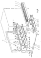
- the storage facility shown in FIG. 1 contains an order-picking device 1 which can be moved along honeycomb shelves 2.
- Fig. 1 only one of these shelves 2 is shown.
- the construction of the honeycomb racks 2 is generally known.
- the stored goods 3 are located in cassettes 4 known per se, only one of which is shown in FIG. 1.
- This cassette 4 is located in one of the end regions of the movement path of the order-picking device 1, from where it can be picked up by the order-picking device 1 and then supplied to one of the shelves 2 in a corresponding compartment.
- two bases 5 and 6 are shown, which stand next to shelf 2.
- On the first base 5 there is the cassette 4 filled with stored goods 3, which is to be supplied in the frame 2.
- An empty cassette 4, which has been removed from the frame 2, can be placed on the second base 6.
- bars, pipes, rails, etc. can be used as storage goods 3.
- the order-picking device 1 moves along the honeycomb racks 2 on rails 7, the end parts of these rails 7 being provided with bumper blocks 8.
- the buffer blocks 8 are opposed to limit switches 9 on the order-picking device 1.
- the order-picking device 1 contains a support frame 10 which extends like a portal between the rails 7. Below are the legs 11 and 12 of the frame 10 in a foot 13 and 14, respectively anchored which parts of a chassis of the order picking device represent.
- the respective foot 13 or 14 is provided with the limit switches 9 and with wheels 15 and 16 which roll on the rails 7.
- the upper parts of the legs 11 and 12 are connected to one another by means of a bar 17.
- a lifting platform 20 extends between the legs 11 and 12.
- This lifting platform 20 has an approximately U-shaped support 21, the legs 22 and 23 of which are hollow.
- the vertical legs 11 and 12 of the support frame 10 pass through the cavities of the legs 22 and 23.
- the legs 11 and 12 and the beam 17 are hollow, so that ropes, rollers and hydraulic lifting cylinders can be accommodated in them, with the aid of which the stage 20 can be moved vertically. By combining the movements in the vertical direction and in the horizontal direction, the lifting platform 20 can reach the desired compartment of the shelves 2.
- the lifting platform 20 also has a cell 25 in or on which the individual devices or devices of the order-picking device 1 are attached.
- This cell 25 contains two frame-shaped cheeks 26 and 27, each of which is fastened to the lifting platform support 21 in the vicinity of the vertical legs 11 and 12.
- the lower front corners of the cheeks 26 and 27 are connected to one another by means of a rigid connecting piece 24.
- the upper vertical sections 28 and .29 of the cheeks 26 and 27 are provided with projecting extensions 31 and 32 which extend in the direction of movement of the order-picking device 1.
- Both the upper sections 28 and 29 and the extensions 31 and 32 of the same are hollow and slotted, so that they can serve as guides for a crane-like device 30 for displacing stored goods 3 in the direction of the movement path of the order-picking device 1.
- the lift is functionally divided into two areas, namely a work platform 35 and a storage goods section 40. These areas extend between the mentioned cheeks 26 and 27 and their length is greater than the length of the longest piece of material stored in the shelves 2.
- the person operating the picking device 1 can be on the work platform 35.
- the actuating elements required for operating the order-picking device 1 can also be located in this area. These are combined in control panels 36 (FIG. 2), one of which is located at least in the respective end region of the work platform 35.
- the floor 65 of the working platform 35 is advantageously designed as a grating. The area of this working platform 35 borders on the lifting platform support 21 in the embodiment of the order-picking device 1 shown in FIG. 1.
- the stored goods section 40 of the lifting platform 20 has a device 45 for handling stored goods 3 and a device 50 for storing stored goods 3.
- the handling device 45 includes the already mentioned crane 30 and a device 41 for moving cassettes 4.
- the crane 30 has a main traverse 33, the end parts of which are mounted in the horizontal parts 28 and 31 and 29 and 32 of the cell 25 and can also be displaced therein.
- Lift cylinders 34 pass through the main cross member 33 and an auxiliary cross member 37 is attached to the piston thereof. From the auxiliary cross member 37, grippers 38 hang down for the individual items 3 to be stored.
- These grippers 38 can be designed as electromagnets, suction elements or simply as hooks for chains or ropes.
- the cassette displacement device 41 contains sets of rollers 43 with a ring distributed along hollow horizontal spacers 42, onto which one of the cassettes 4 can be brought by means of a mechanism 44 known per se. With the aid of the same displacement mechanism 44, the cassette 4 can be removed from such a guideway 43 for the cassettes 4.
- the guideway 43 for the cassettes 4 can also be regarded as one of the components of the storage device 50.
- the storage device 50 also contains a support device 55 for the individual pieces 3 of stored goods and a device 60 for receiving commissions.
- the support device 55 is, as shown in FIG. 1, on the inside of the front wall of the cell 25, while the receiving device 60 is attached to the outside of said front wall.
- These two devices 55 and 60 are designed as storage surfaces which have upwardly directed tines 51.
- These tines 51 form rows which extend parallel to the longitudinal direction of the cell 25 and thus, for example, also to the cross members 33 and 37 and which divide the width of the respective storage surface 55 or 60 into compartments 58 in which the individual commissions or at least the components the same can be kept temporarily.
- the storage surfaces 55 and 60 are formed by support arms 52 protruding from the cell wall, the upper side of which is provided with the prongs 51.
- the intermediate store 70 contains conveyor belts 71 arranged side by side, the outside of which is also provided with tines 51. The distance of these tines 51 from one another is the same as the distance between the tines in the storage area 55 or 60.
- the conveyor belts 71 are mounted on a frame 72, the height of which is selected such that the commissions are easily handled by a standing person can.
- the frame 72 also includes a rail 73 which extends transversely to the direction of movement of the order-picking device 1 and along which a bundling device 75 can be moved.
- the conveyor belts 71 are arranged such that they lie between the support arms 52 of the receiving device 60.
- the commissions that have not yet been bundled can thus simply be placed on the conveyor belts 71, it only being necessary to ensure that the tines 51 of the conveyor belts 71 lie in a row with the tines 51 on the support arms 52. With the help of conveyor belts 71, the respective commission can be brought to the end of the same.
- the person operating the intermediate store 70 can now bind the pieces of material from the commission together with a band from the bundling device 75 as often as required by moving the bundling device 75 along the rail 73.
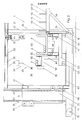
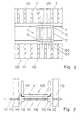
- FIG. 2 shows the order-picking device 1 in a completely lowered position.
- the front posts of the cheeks 26 and 27 are connected to one another at a distance from the bottom region 65 of the cell 25 by means of a further connecting piece 53.
- the inner ends of the support arms 52 are connected to this connecting piece 53, while the outer end parts of the support arms 52 are supported by struts 54 which adjoin the lower connecting piece 24.
- the guideway 43 for the cassette 4 is located directly on the inside of the front wall 53 of the lifting platform cell 25.
- the support device 55 contains rollers 56, the axis of which are approximately perpendicular to the longitudinal direction of the side wall 46.
- the rollers 56 are mounted in brackets 57 and fastened to the side wall 46 with the aid of these. A number of said rollers 56, which are practically at the same height, are distributed over the length of the side wall 46.
- the control panel 36 already mentioned can be attached to the end wall of one or more consoles 57.
- the gripper 38 of the crane 30 above the support device 55 is designed as a hook, the second embodiment of the gripper 38 as an electromagnet also being shown on the right in FIG. 2.
- Cable winches 61 are connected to the main crossbeam 33 of this crane 30, with the aid of which the electromagnets 38 can be lowered to the respective piece of material 3 in order to grip and displace it. From FIG. 2 it can also be seen that the end section of the main crossbeam 33 is connected to carriages 62 which can move inside the upper sections 28 and 31 or 29 and 32 of the cell 25.
- the extension pieces 31 and 32 protrude so far that the crane 30 can also move over the entire length of the receiving device 60, in order to be able to place 60 pieces for a commission even in the most distant compartment 58 of this device.
- the guideway 43 and the support device 55 rest on a plate 63 which is supported on the bottom 65 of the cell 25 by pressure cells 64.
- the control panel 36 is provided with a corresponding display instrument (not shown) from which the weight of the material pieces 3 located on the guideway 43 and the support device 55 can be read.
- FIG. 2 also shows rollers 66 which are located inside the support legs 22 and 23 and which ensure easy guidance of the lifting platform 20 along the legs 11 and 12 of the support frame 10.
- the support device 55 is actually located in the area of the lifting platform 20 which is intended for the person operating the picking device 1.
- the support device 55 can be arranged above the guideway 43, as shown in FIG. 3.
- a support device arranged at this point would, however, hinder access to the inside of the cassette 4 by the crane 30. Therefore, the support device 55 is designed to be horizontally displaceable, so that it extends forward from the region of the guideway 43, ie. H. out of the interior of the cell 25. This can be accomplished with the aid of horizontal hollow rails 68 which are fastened to the inside of the cheeks 26 and 27 at a corresponding height above the floor 65.
- the displacement of the support device 55 can be carried out by hand. In its forward position, the support device is in no way in the way because the crane 30 is above it and because, if necessary, this device 55 can also be moved relative to the compartments 58 defined by the tines 51.
- the device 60 for the temporary reception of unbundled commissions can be removably attached to the cell 25 of the order-picking device 1.
- the device 60 can be fastened, for example, with the aid of screws 69.
- This version of the order-picking device can be of particular advantage if the size of the compartments 58 in the receiving device 60 is to be changed frequently.
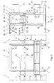
- FIGS. 4 and 5 Another embodiment of the present The system is shown in FIGS. 4 and 5.
- the order-picking device 1 has a work platform 35, the height of which can be set independently of the height of the storage goods section 40.
- the support frame 10 has two frame-shaped parts 96 and 97, which extend perpendicular to the direction of movement of the operating device 1. These frames 96 and 97 are connected at the bottom to the frame feet 13 and 14 and at the top they are connected to one another by means of ties 98.
- the guide track 43 for a cassette 4 is located between the frames 96 and 97, the receiving device 60 together with the extensions 31 projecting from the front of the lift cell.
- the guideway 43 and the receiving device 60 can be moved with the aid of ropes 76 which are guided over deflection rollers 77 which are also located in the supporting frame 10.
- the force required for this is generated either by a cable winch 78 (FIG. 5) or by hydraulic cylinders 79 in the carrier legs 11 and 12.
- the working platform 35 is located on the rear outer side of the support frame 10 and it has the floor 65, to which a railing 82 connects.
- the inside of the platform 35 is provided with a vertically extending support part 83, via which the platform 35 is connected to the support frame 10.
- the platform 35 is provided with rollers 84 and 85, which can be moved in a guided manner on the legs 11 and 12 of the frame 10.
- a drive device 81 is provided which enables the platform 35 to be brought to the desired height. Such drive devices are generally known and therefore this drive device 81 need not be described in more detail here. 5, the platform 351 is also shown in one of its upper layers.
- the platform 35 is provided with a trough 86, in which the individual pieces 3 of stored goods can be pulled in by hand from the honeycomb compartments of the frames 2 and from which the individual pieces 3 can be transferred into the receiving device 60 with the aid of the crane 30. Since it is expected that only individual items will be transported with the aid of the platform 35, the drive 81 of the platform 35 can be designed in such a way that it moves up and down relatively quickly. This saves time in comparison with the case in which, because of individual pieces of stored goods, the stored goods section 40 together with the handling device 45 assigned to it has to be set in motion. The independently movable platform 35 thus enables greater efficiency in the work of the storage facility.
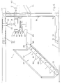
- the measure shown in FIG. 6 leads to a further improvement in the degree of utilization of the storage device.
- the commissioning device 1 has the frame 10, in which the platform 35 and the storage goods section 40 form a whole.
- a staircase 87 which makes it possible to enter or leave the platform 35 and thus also the entire lifting platform at every height adjustment thereof.
- This staircase 87 is connected to the floor 65 of the platform 35 by means of joints 88.
- the cheeks 89 of the stairs 87 are designed as trusses.
- the tread 90 is also articulated to the slope 91 of the respective step 92 below.
- the lower end of the stairs 92 is provided with wheels 93 which can roll on the floor of the warehouse.
- the staircase 87 thus offers the possibility of immediately removing individual items of stored goods from the platform 35 instead of waiting until the entire order-picking device 1 reaches its end position. The same applies in the event that one or more individual items of stored goods are to be stored in the racks.
- the storage goods section 40 of such an order-picking device 1 is provided with the guideway 43 for a cassette 4, which is also provided with the pull-out and pull-in device 44 for handling the cassettes.
- a cassette 4 which is also provided with the pull-out and pull-in device 44 for handling the cassettes.
- On the side wall 46 of the guideway 43 several obliquely extending arms 95 are attached one above the other, which form compartments for the individual items of stored goods.
- Several types of individual pieces can be temporarily stored here. With the help of the crane 30, these individual pieces can also be transferred into the receiving device 60.
- This storage facility is designed in such a way that the desired commissions automatically, i. H. controlled by a computer, can be put together. Such a control works extremely quickly, so that the conditions for a very quick commissioning are given.
- these requirements cannot be sufficiently used in the system described above, because the movements of the order picking device and its components can only be slow due to the large mass of the same.
- the following design of this system eliminates this disadvantage.
- the storage system shown in FIG. 7 contains the order-picking device 1, which can be moved along honeycomb racks 2. Only one of these shelves 2 is shown in FIG. 7, although it should also be said that only part of the rack frame 2 is shown in FIG. 7. Because the honeycomb shelf 2 is usually much longer than shown.
- the stored goods 3 are located in cassettes 4 known per se, of which only three cassettes 4 are shown in FIG. 7. Two of these cassettes 4 are located in the picking device 1, while the third cassette 4 is accommodated in the frame 2. There is only one cassette 4 in each compartment of the frame 2. For example, bars, tubes, rails, etc. can be used as storage goods 3.
- the order-picking device 1 moves along the honeycomb rack 2 on rollers 19 and rails 7.
- the order-picking device 1 contains a support frame 100 which is located between the rails 7 extends.
- This support frame 100 has two portal-like sections 101 and 102 which extend between the rails 7 and which are parallel to one another. Each of these portals 101 and 102 has vertically extending legs 11 and 12 which are connected to one another by a bar 17.
- the portals 101 and 102 are connected at the top by means of a yoke 103, the longitudinal direction of which practically coincides with the direction of movement of the order-picking device 1.
- Below the legs 11 and 12 of the frame 100 are anchored in a foot 13 in which the wheels 19 are located.
- the respective portals 101 and 102 are each assigned a hoist 20 and 201 which extend between the legs 11 and 12 of the relevant portals 101 and 102.
- the respective portal 101 or 102 is provided with drive means (not shown) known per se for the lifting platforms 20 and 201, so that one lifting platform can move independently of the other lifting platform in the vertical direction, ie. H. can move along the legs 11 and 12.
- Fig. 7 the left lift 20 is shown in its lowest position.
- the lifting platform 201 shown on the right in FIG. 7 is shown in one of its upper positions, where it faces one of the compartments 105 of the frame 2.
- the lifting platforms 20 and 201 have an approximately U-shaped and horizontally extending support 21, the legs 22 of which are hollow.
- the vertical legs 11 and 12 of the support frame 100 pass through the cavities in these legs 22.
- the legs 11 and 12, the beams 17 and the yokes 103 are hollow, so that ropes, rollers and hydraulic lifting cylinders can be accommodated in them, with the aid of which the platforms 20 and 201 can be moved in the vertical direction.
- the respective lifting platform 20 or 201 has a cell 25, in or on which the individual devices or devices thereof are attached.
- the cell 25 contains two frame-shaped cheeks 26. That vertical section 106 of the frame 26 which is in the vicinity of the respective leg 22 is fastened to the latter, so that the frame 26 can be moved with the carrier 21 in the vertical direction.
- the lower horizontal sections of the frames 26 are connected to one another by means of a floor 65 of the lifting platform 20.
- the upper horizontal sections 28 of the cheeks 26 are provided with protruding extensions 31 which extend in the direction of movement of the order-picking device 1.
- Both the upper sections 28 of the respective frame 26 and the extensions 31 thereof are hollow and slotted, so that they can serve as guides for a crane-like device 30 for displacing stored goods 3 in the direction of the path of movement of the picking device 1.
- the respective lifting platform 20 is functionally divided into two areas, namely a work platform 35 and a storage goods section 40. These areas extend between the mentioned cheeks 26 and the length of these areas is greater than the length of the longest piece of material 3 stored in the shelves 2 .
- the person operating the picking device 1 can be on the work platform 35.
- the actuating elements required for operating the order-picking device 1 can also be located in this area. These are combined in control panels (not shown), one of which is located at least in the respective end region of the work platform 35.
- the floor 65 of the working platform 35 is advantageously designed as a grating.
- a device 41 for handling cassettes 4 which can be of a type known per se. It has rollers on which the respective cassette 4 can move.
- the device 41 also contains means for pulling out a cassette 4 and for inserting the same.
- the guideway 41 for the cassette 4 is located directly on the inside of the front wall of the lift cell 25.
- the stored goods section 40 of the lifting platform 20 has a device for handling stored goods 3 and a device 50 for storing stored goods 3.
- the handling device includes the crane 30 already mentioned.
- the storage device 50 contains arms 52 for receiving commissions 3 which are attached to the outside of the cell 25 of the lifting platform 20. These arms 52 have storage surfaces which are provided with upwardly directed tines 51. These tines 51 form rows which extend parallel to the longitudinal direction of the cell 25 and which divide the width of the respective storage area into compartments 58 in which the individual commissions 3 or at least components thereof can be temporarily stored.
- the rack frame 2 has posts 110 which form rows, as can be seen clearly from FIG. 8. These posts 110 are connected to one another in the horizontal direction in a manner known per se in such a way that they form the skeleton of an approximately rectangular storage rack 2. Between the posts 110 of adjacent rows of posts there are floors 111 arranged one above the other, on which the respective cassette 4 rests when it is in one of the compartments 105. A compartment 105 thus comprises the respective floor 111 and the cavity above, in which a cassette 4 can be located.
- FIG. 9 shows the essential parts of a shelf compartment 105.
- the end parts of shafts 112 are supported on the posts 110.
- rollers 113 In the area of the end part of the respective shaft 112 there are rollers 113 with a ring 114, the The collar 114 is closer to the post 110 than the cylindrical portion 115 of the respective roller 113.
- the cassette 4 rests on the cylindrical portion 115 of the rollers 113, which are located on successive and horizontally arranged shafts 112.
- the collar 114 prevents the Cassette 4 comes into contact with the post 110. Because this would result in a malfunction of the operation of the storage facility.
- the cassette 4 itself has standing U-pieces 116, which are distributed over the entire length of the cassette 4.
- the lower corner parts of the U-pieces 116 are connected by means of angle iron 117, which extend over the entire length of the cassette 4.
- a lock 125 is implemented in the central area of the frame 2. This lock 125 arises from the fact that the compartments 105 are left out in a specific area of the shelf 2.
- the correspondingly shortened posts 110 are supported on a horizontal support 126.
- the lock 125 there are known devices (not shown) on which the cassettes 4 can be placed if they are to be introduced into or removed from the bearing. This can be the case if empty cassettes 4 are to be refilled or the like.
- the lock 125 in FIG. 7 is made wider than will be the case in practice. Because such a wide lock 125 makes it possible to present the individual parts of the lifting platform 20 in a more manageable manner.
- the width of the lock 125 should actually only correspond to the width of the work platforms 35 of the two lifting platforms 20 and 201 in order to achieve the largest possible volume of the frame 2.
- one of the lifting platforms 20 or 201 moves in the vertical direction in such a way that it reaches the height of the compartment 105 from which the required pieces of material 3 are to be removed.
- the order-picking device 1 also moves towards said compartment 105 in the horizontal direction, if necessary.
- the cassette 4 is pulled out of the compartment 105 and it then rests in the lifting platform on the sliding device 41.
- the operator can use the crane 30 to store the required pieces 3 in the required number 3 in the individual compartments 58 of the device 50. Such work takes a certain amount of time.
- the order picker 1 and the other of the lifting platforms can move so that these other lift f another bearing ach reaches 105 to be removed from the material 3 and in which a cassette 4 is located in this lift is to be deposited.
- cassettes 4 can be loaded or unloaded per unit of time and possibly also brought in through locks than was the case with the known storage facilities.
Claims (13)
Priority Applications (1)
| Application Number | Priority Date | Filing Date | Title |
|---|---|---|---|
| AT86810314T ATE39341T1 (de) | 1985-08-07 | 1986-07-15 | Lageranlage. |
Applications Claiming Priority (4)
| Application Number | Priority Date | Filing Date | Title |
|---|---|---|---|
| CH338185A CH667064A5 (de) | 1985-08-07 | 1985-08-07 | Lageranlage. |
| CH3381/85 | 1985-08-07 | ||
| CH4539/85 | 1985-10-22 | ||
| CH453985A CH667865A5 (de) | 1985-10-22 | 1985-10-22 | Lageranlage. |
Publications (2)
| Publication Number | Publication Date |
|---|---|
| EP0213070A1 EP0213070A1 (fr) | 1987-03-04 |
| EP0213070B1 true EP0213070B1 (fr) | 1988-12-21 |
Family
ID=25692869
Family Applications (1)
| Application Number | Title | Priority Date | Filing Date |
|---|---|---|---|
| EP19860810314 Expired EP0213070B1 (fr) | 1985-08-07 | 1986-07-15 | Dispositif de stockage |
Country Status (2)
| Country | Link |
|---|---|
| EP (1) | EP0213070B1 (fr) |
| DE (1) | DE3661474D1 (fr) |
Families Citing this family (9)
| Publication number | Priority date | Publication date | Assignee | Title |
|---|---|---|---|---|
| DE3707655C1 (de) * | 1987-03-10 | 1988-01-14 | Heinz Dipl-Ing Dornieden | Langmateriallagereinrichtung |
| AT399325B (de) * | 1991-06-12 | 1995-04-25 | Filzmoser Franz | Vorrichtung zum handhaben von langgut |
| US5354169A (en) * | 1991-11-12 | 1994-10-11 | Advanced Technik Gmbh | Storage system for rods |
| EP3018079B1 (fr) * | 2013-07-03 | 2017-03-15 | Sinase Alfonso S.A. | Système automatisé de préparation de commandes d'éléments allongés |
| DE102016101674B4 (de) | 2016-01-29 | 2020-09-17 | Keuro Besitz Gmbh & Co. Edv-Dienstleistungs Kg | Wabenlager sowie Kommissioniereinrichtung und Kommissionierwagen für ein Wabenlager |
| FR3063986B1 (fr) * | 2017-03-16 | 2021-06-18 | Cyrus Bruno Hassan Moini | Tour de stockage automatisee pour elements de type profile et methode associee |
| CN107628078A (zh) * | 2017-08-30 | 2018-01-26 | 新乡市巨能合成材料有限公司 | 一种多功能仓储 |
| CN108545662A (zh) * | 2018-07-02 | 2018-09-18 | 湖州维欧瑞自动化机械设备有限公司 | 一种仓储设备货物存放用升降装置 |
| CN115744342B (zh) * | 2022-10-21 | 2023-06-27 | 北京中投润天环保科技有限公司 | 膏体状物料储存输送设备 |
Family Cites Families (3)
| Publication number | Priority date | Publication date | Assignee | Title |
|---|---|---|---|---|
| DE2154709C3 (de) * | 1971-11-04 | 1981-04-09 | Erwin Mehne GmbH & Co, 7100 Heilbronn | Regalförderzeug |
| EP0116152A3 (fr) * | 1982-12-14 | 1985-12-04 | GOLDBECKBAU GMBH & CO. KG | Dispositif pour stocker et retirer des profilés |
| DE3306673A1 (de) * | 1983-02-25 | 1984-09-06 | Schlosserei Klaus Matthiessen GmbH, 2374 Fockbek | Regalanordnung |
-
1986
- 1986-07-15 EP EP19860810314 patent/EP0213070B1/fr not_active Expired
- 1986-07-15 DE DE8686810314T patent/DE3661474D1/de not_active Expired
Also Published As
| Publication number | Publication date |
|---|---|
| DE3661474D1 (en) | 1989-01-26 |
| EP0213070A1 (fr) | 1987-03-04 |
Similar Documents
| Publication | Publication Date | Title |
|---|---|---|
| EP0458021B1 (fr) | Entrepôt avec rayonnages pour matériel recueilli dans des cassettes autoporteuses | |
| EP1695925B1 (fr) | Magasin à rayonnage et procédé pour transférer d'articles dans un magasin à rayonnage | |
| EP0268965B1 (fr) | Dispositif de stockage | |
| EP1716060A1 (fr) | Procede et systeme pour se servir d'un rayon dans un dispositif de preparation des commandes | |
| EP0407703A1 (fr) | Procédé et dispositif pour stocker et déstocker des caissons contenant des matériaux en forme de bâton ou de plaque dans un magasin à rayonnage | |
| DE4213542A1 (de) | Regalanordnung | |
| DE102018117096A1 (de) | Transporteinheit für ein Hochregallager | |
| EP2145842B1 (fr) | Rayonnage | |
| EP0029073B1 (fr) | Magasin pour le stockage de marchandises de détail | |
| EP0589844B1 (fr) | Magasin à haute performance avec des moyens pour stocker et prélever des marchandises | |
| CH680212A5 (en) | Shelf service equipment for high level shelf storage - enables bundles to circulate on intermediate storage conveyor which allows access to other bundles behind them | |
| EP0213070B1 (fr) | Dispositif de stockage | |
| EP2746193B1 (fr) | Véhicule pour entrepôt, transstockeur, entrepôt et procédé correspondant | |
| EP0213289A1 (fr) | Dispositif pour stocker et déstocker des marchandises d'un rayonnage en nid d'abeilles | |
| EP0116152A2 (fr) | Dispositif pour stocker et retirer des profilés | |
| DE102015101948A1 (de) | System aus Regaleinrichtung und korrespondierendem teleskopierbarem Lastaufnahmemittel ohne Breitenverstellung | |
| EP0379688A1 (fr) | Dispositif pour la prise en stock et la remise en stock de colis | |
| DE202018102035U1 (de) | Regalbediengerät und Regallager mit einem solchen Regalbediengarät | |
| EP0798238B1 (fr) | Système d'entreposage pour palettes pour objets longs | |
| DE4010905C2 (fr) | ||
| DE4142355A1 (de) | Verfahrbare krananlage | |
| CH667865A5 (de) | Lageranlage. | |
| CH667064A5 (de) | Lageranlage. | |
| EP0013033A1 (fr) | Dispositif de prélèvement, en particulier pour prélever un matériau en barres ou analogue, des cassettes d'un rayonnage | |
| DE2540252A1 (de) | Einrichtung zum lagern von palettierten, sowie flaechen- und stabfoermigen teilen |
Legal Events
| Date | Code | Title | Description |
|---|---|---|---|
| PUAI | Public reference made under article 153(3) epc to a published international application that has entered the european phase |
Free format text: ORIGINAL CODE: 0009012 |
|
| AK | Designated contracting states |
Kind code of ref document: A1 Designated state(s): AT BE CH DE FR GB IT LI LU NL SE |
|
| 17P | Request for examination filed |
Effective date: 19870902 |
|
| 17Q | First examination report despatched |
Effective date: 19880518 |
|
| GRAA | (expected) grant |
Free format text: ORIGINAL CODE: 0009210 |
|
| AK | Designated contracting states |
Kind code of ref document: B1 Designated state(s): AT BE CH DE FR GB IT LI LU NL SE |
|
| PG25 | Lapsed in a contracting state [announced via postgrant information from national office to epo] |
Ref country code: IT Free format text: LAPSE BECAUSE OF FAILURE TO SUBMIT A TRANSLATION OF THE DESCRIPTION OR TO PAY THE FEE WITHIN THE PRE;WARNING: LAPSES OF ITALIAN PATENTS WITH EFFECTIVE DATE BEFORE 2007 MAY HAVE OCCURRED AT ANY TIME BEFORE 2007. THE CORRECT EFFECTIVE DATE MAY BE DIFFERENT FROM THE ONE RECORDED.SCRIBED TIME-LIMIT Effective date: 19881221 Ref country code: GB Free format text: LAPSE BECAUSE OF NON-PAYMENT OF DUE FEES Effective date: 19881221 Ref country code: BE Effective date: 19881221 |
|
| REF | Corresponds to: |
Ref document number: 39341 Country of ref document: AT Date of ref document: 19890115 Kind code of ref document: T |
|
| REF | Corresponds to: |
Ref document number: 3661474 Country of ref document: DE Date of ref document: 19890126 |
|
| ET | Fr: translation filed | ||
| GBV | Gb: ep patent (uk) treated as always having been void in accordance with gb section 77(7)/1977 [no translation filed] | ||
| PG25 | Lapsed in a contracting state [announced via postgrant information from national office to epo] |
Ref country code: LU Free format text: LAPSE BECAUSE OF NON-PAYMENT OF DUE FEES Effective date: 19890731 |
|
| GBV | Gb: ep patent (uk) treated as always having been void in accordance with gb section 77(7)/1977 [no translation filed] | ||
| PLBE | No opposition filed within time limit |
Free format text: ORIGINAL CODE: 0009261 |
|
| STAA | Information on the status of an ep patent application or granted ep patent |
Free format text: STATUS: NO OPPOSITION FILED WITHIN TIME LIMIT |
|
| 26N | No opposition filed | ||
| EAL | Se: european patent in force in sweden |
Ref document number: 86810314.4 |
|
| PGFP | Annual fee paid to national office [announced via postgrant information from national office to epo] |
Ref country code: FR Payment date: 19950717 Year of fee payment: 10 |
|
| PGFP | Annual fee paid to national office [announced via postgrant information from national office to epo] |
Ref country code: NL Payment date: 19950731 Year of fee payment: 10 Ref country code: AT Payment date: 19950731 Year of fee payment: 10 |
|
| PGFP | Annual fee paid to national office [announced via postgrant information from national office to epo] |
Ref country code: DE Payment date: 19950908 Year of fee payment: 10 |
|
| PGFP | Annual fee paid to national office [announced via postgrant information from national office to epo] |
Ref country code: CH Payment date: 19951013 Year of fee payment: 10 |
|
| PG25 | Lapsed in a contracting state [announced via postgrant information from national office to epo] |
Ref country code: AT Effective date: 19960715 |
|
| PGFP | Annual fee paid to national office [announced via postgrant information from national office to epo] |
Ref country code: SE Payment date: 19960719 Year of fee payment: 11 |
|
| PG25 | Lapsed in a contracting state [announced via postgrant information from national office to epo] |
Ref country code: CH Effective date: 19960731 Ref country code: LI Effective date: 19960731 |
|
| PG25 | Lapsed in a contracting state [announced via postgrant information from national office to epo] |
Ref country code: NL Effective date: 19970201 |
|
| REG | Reference to a national code |
Ref country code: CH Ref legal event code: PL |
|
| PG25 | Lapsed in a contracting state [announced via postgrant information from national office to epo] |
Ref country code: FR Effective date: 19970328 |
|
| NLV4 | Nl: lapsed or anulled due to non-payment of the annual fee |
Effective date: 19970201 |
|
| PG25 | Lapsed in a contracting state [announced via postgrant information from national office to epo] |
Ref country code: DE Effective date: 19970402 |
|
| REG | Reference to a national code |
Ref country code: FR Ref legal event code: ST |
|
| PG25 | Lapsed in a contracting state [announced via postgrant information from national office to epo] |
Ref country code: SE Effective date: 19970716 |
|
| EUG | Se: european patent has lapsed |
Ref document number: 86810314.4 |