EP0457955B1 - Procédé pour éviter le maculage et appareil pour utilisation avec les cylindres de retournement des machines rotatives d'impression de feuilles - Google Patents
Procédé pour éviter le maculage et appareil pour utilisation avec les cylindres de retournement des machines rotatives d'impression de feuilles Download PDFInfo
- Publication number
- EP0457955B1 EP0457955B1 EP90114866A EP90114866A EP0457955B1 EP 0457955 B1 EP0457955 B1 EP 0457955B1 EP 90114866 A EP90114866 A EP 90114866A EP 90114866 A EP90114866 A EP 90114866A EP 0457955 B1 EP0457955 B1 EP 0457955B1
- Authority
- EP
- European Patent Office
- Prior art keywords
- covering
- sheet
- press
- set forth
- coating
- Prior art date
- Legal status (The legal status is an assumption and is not a legal conclusion. Google has not performed a legal analysis and makes no representation as to the accuracy of the status listed.)
- Expired - Lifetime
Links
Images


Classifications
-
- B—PERFORMING OPERATIONS; TRANSPORTING
- B41—PRINTING; LINING MACHINES; TYPEWRITERS; STAMPS
- B41F—PRINTING MACHINES OR PRESSES
- B41F22/00—Means preventing smudging of machine parts or printed articles
Definitions
- This invention relates to printing presses, and more particularly, to an anti-marking method and apparatus for preventing the marking and marring of printed sheets in a high speed, sheet-fed multicolor rotary printing press of the type having a perfecting cylinder for permitting either one sided or two sided printing.
- the perfecting cylinder is adjustably timed with respect to the storage drum such that the perfecting cylinder either transfers the sheet, leading edge first, to the second printing station where a second color ink is applied to the same side previously printed (referred to as one sided or non-perfector mode printing), or the sheet is reversed and transferred to the second printing station trailing or tail edge first for printing on the reverse side (referred to as perfector mode printing).
- sheet grippers carried by the perfecting cylinder which project radially from a longitudinal opening formed along the length of the cylinder, are timed to grip the tail edge of the sheet from the storage drum after the leading edge of the sheet on the storage drum has passed through the nip between the perfecting cylinder and the storage drum, and to pull the sheet from the storage drum with the non-printed side supported by the surface of the perfecting cylinder.
- the leading edge of the sheet is gripped by the grippers of the perfecting cylinder at the nip, and pulled from the storage drum with the wet inked side facing and supported by the surface of the perfecting cylinder.
- the storage drum typically is sized to have a diameter twice that of the perfecting cylinder, and carries two sets of diametrically opposed sheet gripper mechanisms, each set comprising sheet grippers for the leading edge of the sheet and sheet grippers for the tail edge of the sheet. Since the perfecting cylinder must allow the leading edge of the sheet carried by the storage drum to pass through the nip when the press is used in the perfector mode, the supporting surface of the perfecting cylinder is provided with a series of longitudinally spaced circumferential channels or grooves which allow the leading edge sheet grippers of the storage drum to pass through the nip.
- the perfecting cylinder operates to reverse the sheet so that the non-inked side of the sheet is carried by the supporting surface of the perfecting cylinder, and marking and marring of the freshly printed sheet can not occur.
- marking and marring of the freshly printed sheet has been found to occur when the press is used in the non-perfector mode since the perfecting cylinder merely acts as a conventional press transfer cylinder with the printed side of the sheet carried against the supporting surface of the perfecting cylinder during the transfer and the grooved surface does not provide uniform sheet support.
- the loosely mounted net attaches and clings to the wet inked side of the freshly printed sheet as the sheet is supported by the transfer cylinder such that any relative motion between the sheet and the cylinder takes place between the surface of the net and the low friction coated surface of the cylinder so that marking and marring of the freshly printed surface does not occur.
- the method and apparatus of the present invention prevents marking and marring of the freshly printed sheets during use of a press in the non-perfector mode of operation by removably mounting a smooth, substantially rigid, low friction coated covering over the grooved support surface of the perfecting cylinder, and to which an anti-marking net can be attached.
- mounting means are provided which clamp the covering directly to the existing pillow blocks supporting the gripper mechanism of the perfecting cylinder so that no boring or other modifications are required to be made to the perfecting cylinder or its gripper mechanism.
- the covering is formed as a generally C-shaped member having lateral and longitudinal side edges dimensioned to overlie the supporting surface of the perfecting cylinder, and the coating, which preferably is polytetrafluoroethylene, is formed on the radially outer face of the covering facing the sheet.
- the mounting means comprise specially designed retainer clips which include hook portions for releasably engaging elongated rods attached to the longitudinal side edges of the covering to clamp the covering in position over the perfecting cylinder.
- the covering is formed as a laminate with a base portion made from a generally rigid plastic material such as polystyrene, and a tightly woven fabric web to one side of which is bonded the friction reducing coating.
- a fastening strip preferably VELCRO, is secured over the coating along the lateral and longitudinal side edges of the covering, and functions to permit the anti-marking net to be removably attached to the covering.
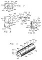
- the perfecting cylinder 10 is positioned in a press to receive a sheet which has been printed on one side in a conventional first printing station, herein generally designated by the reference numeral 12, and convey that sheet to a conventional second printing station, generally designated by the reference numeral 14.
- each printing station 12 and 14 includes a plate cylinder 16; a blanket cylinder 18; an impression cylinder 20; and a transfer cylinder 22, and the initial printing station 12 is provided with a sheet feed roller 24 which feeds individual sheets one at a time from a conventional feeder 26 to the initial impression cylinder for printing.
- Each of the impression cylinders 20, and transfer cylinders 22, as well as the sheet feed roller 24 is provided with a sheet gripper mechanism, generally designated 28, which grips the leading edge of the sheet to pull the sheet around the cylinder in the direction of the associated arrows shown.
- the function and operation of the cylinders and associated grippers of the printing stations 12 and 14 are believed to be well known to those familiar with multicolor sheet fed presses, and need not be described further except to note that the impression cylinders 20 function to press the sheets against the blanket cylinders 18 which apply ink to the sheets, and the transfer cylinders 22 convey the sheets away from the impression cylinders with the wet inked sides facing the support surfaces of the transfer cylinders.
- marking and marring of the freshly printed sheet during use of the press in the non-perfector mode of operation is prevented by removably mounting a smooth, relatively rigid, low friction covering, generally designated by reference numeral 62 in Fig. 2, over the grooved support surface 44 of the perfecting cylinder 10.
Claims (28)
- Presse d'impression rotative à feuille du type comportant un cylindre de retournement pour permettre à la presse de fonctionner pour une impression de la feuille en recto ou en recto-verso, le cylindre de retournement comportant une surface de support généralement cylindrique comprenant des rainures circonférentielles espacées dans le sens longitudinal formées le long de celle-ci dans le sens axial et prévu pour supporter le côté non encré d'une feuille imprimée lorsque ladite presse fonctionne en mode d'impression recto-verso et pour supporter le côté encré humide d'une feuille imprimée lorsque ladite presse fonctionne en mode d'impression recto, caractérisée en ce que
lorsque ladite presse fonctionne dans ledit mode d'impression recto, celle-ci comprend :
un habillage sensiblement rigide, généralement en forme de C comportant des bords de côtés latéraux et longitudinaux espacés, dimensionnés pour recouvrir ladite surface de support de feuille dudit cylindre de retournement et comportant une couche de revêtement de diminution du frottement sensiblement uniforme sur l'une de ses faces,
des moyens pour monter de manière détachable ledit habillage sur ladite surface de support de feuille dudit cylindre de retournement, ladite couche de revêtement étant disposée en orientation externe dans le sens radial vers ladite feuille, d'où il résulte que, lorsque ladite presse fonctionne dans ledit mode d'impression recto, ledit côté imprimé humide de ladite feuille imprimée est supporté de manière uniforme par ledit habillage sensiblement rigide. - Presse selon la revendication 1, dans laquelle lesdits moyens de montage comprennent des dispositifs de retenue fixés de manière permanente sur ledit cylindre de retournement et en ce que ledit habillage est fixé de manière détachable sur ladite surface de support par lesdits dispositifs de retenue.
- Presse selon la revendication 1, dans laquelle un filet de tissu anti-maculage est fixé de manière détachable audit habillage sur ladite couche de revêtement.
- Presse selon la revendication 1, dans laquelle ledit habillage est formé à partir d'une matière plastique généralement rigide.
- Presse selon la revendication 4, dans laquelle ladite couche de revêtement est formée sur un substrat stratifié sur ladite face dudit habillage.
- Presse selon la revendication 5, dans laquelle ladite couche de revêtement est en polytétrafluoroéthylène fixé audit substrat.
- Presse selon la revendication 2, dans laquelle ledit habillage comprend des tiges s'étendant dans le sens axial fixées à auxdits bords de côtés longitudinaux et lesdits dispositifs de retenue comprennent des parties de crochet s'engageant avec lesdites tiges de manière détachable.
- Presse selon la revendication 7, dans laquelle un filet de tissu anti-maculage est fixé de manière détachable audit habillage sur ladite couche de revêtement.
- Presse selon la revendication 8, dans laquelle ledit habillage est formé à partir d'une matière plastique généralement rigide.
- Presse selon la revendication 9, dans laquelle ladite couche de revêtement est en polytétrafluoroéthylène.
- Presse selon la revendication 10, dans laquelle ladite couche de revêtement est formée sur un tissu stratifié sur ladite face de ladite matière plastique.
- Presse selon la revendication 11, dans laquelle une bande de fixation est fixée audit habillage sur ladite couche de revêtement le long desdits bords de côtés latéraux et longitudinaux.
- Presse d'impression rotative à feuilles du type comportant un cylindre de retournement pour permettre à la presse de fonctionner en impression de feuille recto ou recto-verso, le cylindre de retournement comportant une surface de support de feuille dans laquelle sont formées des rainures circonférentielles espacées dans le sens longitudinal en suivant son sens axial et qui est prévu pour supporter le côté non encré de ladite feuille lorsque ladite presse fonctionne en mode d'impression recto-verso et pour supporter le côté encré humide de ladite feuille lorsque ladite presse fonctionne en mode d'impression recto et comportant un canal allongé s'étendant dans le sens axial formé dans la surface de support à l'intérieur de laquelle est monté un mécanisme de transport de feuilles à pinces supporté par des blocs de palier fixés par boulons au cylindre de retournement à l'intérieur dudit canal, un dispositif pour empêcher le maculage et le gâchage des feuilles imprimées par ledit cylindre de retournement lorsque ladite presse fonctionne dans ledit mode d'impression recto comprenant :
un habillage sensiblement rigide généralement en forme de C comportant des bords de côtés latéraux et longitudinaux dimensionnés pour recouvrir lesdites surfaces de support dudit cylindre de retournement et comportant une couche de revêtement de diminution du frottement sur sa face radialement externe,
un filet de tissu anti-maculage fixé de manière détachable audit habillage sur ladite couche de revêtement de diminution du frottement, et
des moyens pour monter de manière détachable ledit habillage sur ladite surface de support de feuille rainurée, ledit filet anti-maculage étant disposé en regard de ladite feuille, ce qui permet que lorsque ladite presse fonctionne dans ledit mode d'impression recto, ledit côté encré humide de ladite feuille imprimée soit engagé avec ledit filet et soit supporté sur ledit habillage sensiblement rigide. - Appareil selon la revendication 13, dans lequel lesdits moyens de montage comprennent des dispositifs de retenue fixés de manière permanente par lesdits boulons sur lesdits blocs de palier et dans lequel ledit habillage est couplé de manière détachable auxdits dispositifs de retenue.
- Appareil selon la revendication 14, dans lequel ledit habillage est formé à partir d'une matière plastique généralement rigide.
- Appareil selon la revendication 15, dans lequel ladite couche de revêtement est en polytétrafluoroéthylène.
- Appareil selon la revendication 13, dans lequel ledit habillage est formé d'une feuille en matière plastique généralement rigide et dans lequel ladite couche de revêtement est formée sur un substrat stratifié au recto de ladite feuille plastique.
- Appareil selon la revendication 17, dans lequel ladite matière de feuille plastique est en polystyrène.
- Appareil selon la revendication 18, dans lequel ladite couche de revêtement est formée à partir de polytétrafluoroéthylène collé audit substrat.
- Appareil selon la revendication 19, dans lequel ledit filet est fixé audit habillage par une bande de fixation fixée sur ladite couche de revêtement autour desdits bords de côtés latéraux et longitudinaux.
- Habillage destiné à être utilisé avec un cylindre de retournement dans une presse d'impression rotative à feuilles du type apte à imprimer des feuilles soit recto soit recto-verso, le cylindre de retournement comportant une surface de support rainurée destinée à supporter le côté non encré de la feuille imprimée lorsque la presse fonctionne en mode retournement pour une impression recto-verso et pour supporter le côté encré humide de la feuille lorsque la presse fonctionne en mode non retournement pour impression recto, ledit habillage comprenant :
une base en forme de C sensiblement rigide formée d'une matière plastique généralement rigide et comportant des bords de côtés latéraux et longitudinaux dimensionnés pour recouvrir ladite surface de support rainurée dudit cylindre de retournement,
une couche de revêtement de diminution du frottement formée sur ladite face radialement externe de ladite base en forme de C, et
des moyens couplés à ladite base pour fixer de manière détachable ladite base sur ledit cylindre de retournement au-dessus de ladite surface de support rainurée. - Habillage selon la revendication 21, dans lequel lesdits moyens pour fixer de manière détachable ladite base comprennent des tiges allongées couplées auxdits bords de côtés longitudinaux.
- Habillage selon la revendication 21, dans lequel ladite matière plastique est de polystyrène.
- Habillage selon la revendication 21, dans lequel ladite couche de revêtement est formée sur un substrat stratifié sur ladite base.
- Habillage selon la revendication 24, dans lequel ladite couche de revêtement est en polytétrafluoroéthylène.
- Habillage selon la revendication 25, dans lequel ladite matière plastique est de polystyrène.
- Procédé pour empêcher le maculage et le gâchage du côté encre humide d'une feuille imprimée pendant le passage de la feuille sur la surface de support de feuille rainurée d'un cylindre de retournement dans une presse d'impression rotative à feuilles du type apte à être utilisée pour une impression de feuille recto ou recto-verso lorsque la presse fonctionne en mode d'impression recto, comprenant les étapes consistant à :
réaliser un habillage sensiblement rigide dimensionné pour recouvrir la surface de support du cylindre de retournement et comportant une couche de revêtement de diminution du frottement sur l'une de ses faces,
positionner ledit habillage sur la surface de support rainurée du cylindre de retournement, ladite couche de revêtement de diminution du frottement étant disposée en regard de la feuille, et
fixer de manière détachable ledit habillage audit cylindre de retournement de façon à recouvrir presque entièrement la surface de support rainurée. - Procédé selon la revendication 27, comprenant en outre l'étape consistant à fixer de manière amovible un filet de tissu anti-maculage sur ledit habillage au-dessus de ladite couche de revêtement de diminution du frottement.
Applications Claiming Priority (2)
| Application Number | Priority Date | Filing Date | Title |
|---|---|---|---|
| US07/516,523 US5042384A (en) | 1990-04-30 | 1990-04-30 | Anti-marking method and apparatus for use with perfector cylinders of rotary sheet-fed printing presses |
| US516523 | 1990-04-30 |
Publications (2)
| Publication Number | Publication Date |
|---|---|
| EP0457955A1 EP0457955A1 (fr) | 1991-11-27 |
| EP0457955B1 true EP0457955B1 (fr) | 1994-06-29 |
Family
ID=24055961
Family Applications (1)
| Application Number | Title | Priority Date | Filing Date |
|---|---|---|---|
| EP90114866A Expired - Lifetime EP0457955B1 (fr) | 1990-04-30 | 1990-08-02 | Procédé pour éviter le maculage et appareil pour utilisation avec les cylindres de retournement des machines rotatives d'impression de feuilles |
Country Status (6)
| Country | Link |
|---|---|
| US (1) | US5042384A (fr) |
| EP (1) | EP0457955B1 (fr) |
| JP (1) | JP2567157B2 (fr) |
| CA (1) | CA2021854C (fr) |
| DD (1) | DD299165A5 (fr) |
| DE (1) | DE69010323T2 (fr) |
Families Citing this family (15)
| Publication number | Priority date | Publication date | Assignee | Title |
|---|---|---|---|---|
| US6192800B1 (en) | 1994-06-14 | 2001-02-27 | Howard W. DeMoore | Method and apparatus for handling printed sheet material |
| US6119597A (en) * | 1994-06-14 | 2000-09-19 | Howard W. DeMoore | Method and apparatus for handling printed sheet material |
| US5907998A (en) * | 1995-12-29 | 1999-06-01 | Howard W. Demoore | Anti-static, anti-smearing pre-stretched and pressed flat, precision-cut striped flexible coverings for transfer cylinders |
| US5660108A (en) * | 1996-04-26 | 1997-08-26 | Presstek, Inc. | Modular digital printing press with linking perfecting assembly |
| US5979322A (en) * | 1996-05-07 | 1999-11-09 | Demoore; Howard Warren | Environmentally safe, ink repellent, anti-marking flexible jacket covering having alignment stripes, centering marks and pre-fabricated reinforcement strips for attachment onto transfer cylinders in a printing press |
| US5842412A (en) * | 1997-03-07 | 1998-12-01 | Bba Nonwovens Simpsonville, Inc. | Anti-marking covering for printing press transfer cylinder |
| DE19949412A1 (de) * | 1999-10-13 | 2001-04-19 | Heidelberger Druckmasch Ag | Einrichtung zum Wenden von Bogen in einer Bogenrotationsdruckmaschine |
| US6811863B2 (en) | 2001-07-20 | 2004-11-02 | Brite Ideas, Inc. | Anti-marking coverings for printing presses |
| US6748863B2 (en) * | 2002-06-11 | 2004-06-15 | Mark Miller | Method and apparatus for transferring printed sheets |
| EP1589855B1 (fr) * | 2003-01-30 | 2014-07-16 | Joseph Rocco Pacione | Feuille d'ancrage |
| EP1514683B1 (fr) * | 2003-09-09 | 2013-06-05 | Koenig & Bauer Aktiengesellschaft | Procédé pour faire fonctionner une machine à imprimer |
| JP4644615B2 (ja) * | 2006-03-16 | 2011-03-02 | 篠田商事株式会社 | インキ汚れ防止シート |
| US20070235923A1 (en) * | 2006-04-05 | 2007-10-11 | Keller James J | Sheet feeder, feed roller system and method |
| WO2007133715A2 (fr) * | 2006-05-12 | 2007-11-22 | Printguard, Inc. | dispositif de serrage pour couvertures antimarquage pour presses d'impression |
| JP2022048678A (ja) * | 2020-09-15 | 2022-03-28 | 富士フイルムビジネスイノベーション株式会社 | 胴部材及び画像形成装置 |
Family Cites Families (15)
| Publication number | Priority date | Publication date | Assignee | Title |
|---|---|---|---|---|
| US2085845A (en) * | 1934-09-19 | 1937-07-06 | Carborundum Co | Printing apparatus |
| US2285060A (en) * | 1940-03-16 | 1942-06-02 | Schmutz Mfg Co | Flexible printing plate |
| US3261288A (en) * | 1964-06-08 | 1966-07-19 | Henry R Dickerson | Antismear jacket for transfer drum |
| DE2914362C3 (de) * | 1979-04-09 | 1984-12-20 | Heidelberger Druckmaschinen Ag, 6900 Heidelberg | Bogentransporttrommel an Rotationsdruckmaschinen |
| DK40181A (da) * | 1980-03-31 | 1981-10-01 | Heidelberger Druckmasch Ag | Arkoverfoeringscylinder for rotationstrykmaskine |
| JPS57108942U (fr) * | 1980-12-26 | 1982-07-05 | ||
| US4402267A (en) * | 1981-03-11 | 1983-09-06 | Printing Research Corporation | Method and apparatus for handling printed sheet material |
| JPS6022343U (ja) * | 1983-07-25 | 1985-02-15 | 株式会社小森コーポレーション | 輪転印刷機のブランケツト咥え装置 |
| DE3413158C2 (de) * | 1984-04-07 | 1986-02-27 | Heidelberger Druckmaschinen Ag, 6900 Heidelberg | Bogenrotationsdruckmaschine zur Herstellung von einseitigem Mehrfarbendruck oder Schön- und Widerdruck |
| DE3419762A1 (de) * | 1984-05-26 | 1985-11-28 | Heidelberger Druckmaschinen Ag, 6900 Heidelberg | Bogen-rotationsdruckmaschine in reihenbauart der druckwerke |
| JPS6131740U (ja) * | 1984-07-30 | 1986-02-26 | 百城 須藤 | 回転胴取付け用インキ汚れ防止シ−ト |
| US4694750A (en) * | 1985-11-21 | 1987-09-22 | Greene Joe A | Printing press cylinder with axially adjustable cord anti-smear devices |
| US4691632A (en) * | 1986-07-08 | 1987-09-08 | Demoore Howard W | Method and apparatus for attaching anti-smear net to printing press transfer cylinder |
| JP2656771B2 (ja) * | 1987-08-06 | 1997-09-24 | ダブリュー デムーア ハワード | 汚れ防止布ウェブ取付け方法及び装置 |
| JP3031546U (ja) * | 1996-05-09 | 1996-11-29 | 新日本製鐵株式会社 | 曲げ加工機 |
-
1990
- 1990-04-30 US US07/516,523 patent/US5042384A/en not_active Expired - Lifetime
- 1990-07-24 CA CA002021854A patent/CA2021854C/fr not_active Expired - Fee Related
- 1990-08-02 DE DE69010323T patent/DE69010323T2/de not_active Expired - Fee Related
- 1990-08-02 EP EP90114866A patent/EP0457955B1/fr not_active Expired - Lifetime
- 1990-10-01 DD DD90344325A patent/DD299165A5/de unknown
-
1991
- 1991-03-28 JP JP3064971A patent/JP2567157B2/ja not_active Expired - Fee Related
Also Published As
| Publication number | Publication date |
|---|---|
| JPH04229266A (ja) | 1992-08-18 |
| EP0457955A1 (fr) | 1991-11-27 |
| US5042384A (en) | 1991-08-27 |
| DE69010323T2 (de) | 1994-12-08 |
| CA2021854C (fr) | 1994-05-31 |
| CA2021854A1 (fr) | 1991-10-31 |
| DE69010323D1 (de) | 1994-08-04 |
| JP2567157B2 (ja) | 1996-12-25 |
| DD299165A5 (de) | 1992-04-02 |
Similar Documents
| Publication | Publication Date | Title |
|---|---|---|
| EP0457955B1 (fr) | Procédé pour éviter le maculage et appareil pour utilisation avec les cylindres de retournement des machines rotatives d'impression de feuilles | |
| EP0059944B1 (fr) | Procédé et dispositif de manipulation de feuilles imprimées | |
| US3296673A (en) | Printing blanket edging and anchoring means | |
| US4815379A (en) | Sheet transfer cylinder between printing units of a rotary printing machine | |
| EP0412236B1 (fr) | Dispositif à rouleaux de transfert pour machine d'impression et matière textile pour ceux-ci | |
| US5176077A (en) | Coating apparatus for sheet-fed, offset rotary printing presses | |
| US5205217A (en) | Vacuum transfer apparatus for rotary sheet-fed printing presses | |
| US5435242A (en) | Plate cylinder for a printing press having plate material in a cartridge within the plate cylinder | |
| CA2185525A1 (fr) | Presse d'impression a plusieurs couleurs | |
| CA2148737A1 (fr) | Presse lithographique a distorsion reduite | |
| US5088404A (en) | Delivery apparatus for printing press | |
| CA2227178A1 (fr) | Rotative offset a feuilles | |
| CA2116353A1 (fr) | Mecanisme a pinces servant au transfert des feuilles lors del'impression sur presse offset a couloirs multiples | |
| EP0491110B1 (fr) | Dispositif de transport à dépression pour une machine d'impression rotative pour feuilles | |
| JPH0433275B2 (fr) | ||
| US4694750A (en) | Printing press cylinder with axially adjustable cord anti-smear devices | |
| WO2012106162A2 (fr) | Chemises anti-marquages réversibles et procédés d'utilisation | |
| CA2024597A1 (fr) | Devidoir de toile protectrice pour cylindres de transport ou de reception d'une presse rotative | |
| US4691632A (en) | Method and apparatus for attaching anti-smear net to printing press transfer cylinder | |
| US6655270B2 (en) | Printing unit having screen printing cylinders and transfer cylinders forming printing nip | |
| CA1202523A (fr) | Porte-cylindres pour rotative d'impression offset alimentee feuille par feuille | |
| US5390597A (en) | Offset press | |
| CA2352854C (fr) | Mecanisme d'enroulement a double plaque dote d'un reglage de tension | |
| US5131326A (en) | Cover mounting for a printing press | |
| JP2918491B2 (ja) | リソグラフ印刷プレート用クランプアセンブリ |
Legal Events
| Date | Code | Title | Description |
|---|---|---|---|
| PUAI | Public reference made under article 153(3) epc to a published international application that has entered the european phase |
Free format text: ORIGINAL CODE: 0009012 |
|
| AK | Designated contracting states |
Kind code of ref document: A1 Designated state(s): CH DE FR GB IT LI SE |
|
| 17P | Request for examination filed |
Effective date: 19920408 |
|
| 17Q | First examination report despatched |
Effective date: 19930910 |
|
| GRAA | (expected) grant |
Free format text: ORIGINAL CODE: 0009210 |
|
| AK | Designated contracting states |
Kind code of ref document: B1 Designated state(s): CH DE FR GB IT LI SE |
|
| REF | Corresponds to: |
Ref document number: 69010323 Country of ref document: DE Date of ref document: 19940804 |
|
| ET | Fr: translation filed | ||
| ITF | It: translation for a ep patent filed |
Owner name: ORGANIZZAZIONE D'AGOSTINI |
|
| EAL | Se: european patent in force in sweden |
Ref document number: 90114866.8 |
|
| PLBE | No opposition filed within time limit |
Free format text: ORIGINAL CODE: 0009261 |
|
| STAA | Information on the status of an ep patent application or granted ep patent |
Free format text: STATUS: NO OPPOSITION FILED WITHIN TIME LIMIT |
|
| 26N | No opposition filed | ||
| REG | Reference to a national code |
Ref country code: GB Ref legal event code: IF02 |
|
| PGFP | Annual fee paid to national office [announced via postgrant information from national office to epo] |
Ref country code: GB Payment date: 20040728 Year of fee payment: 15 |
|
| PGFP | Annual fee paid to national office [announced via postgrant information from national office to epo] |
Ref country code: SE Payment date: 20040819 Year of fee payment: 15 Ref country code: FR Payment date: 20040819 Year of fee payment: 15 |
|
| PGFP | Annual fee paid to national office [announced via postgrant information from national office to epo] |
Ref country code: CH Payment date: 20040823 Year of fee payment: 15 |
|
| PGFP | Annual fee paid to national office [announced via postgrant information from national office to epo] |
Ref country code: DE Payment date: 20040930 Year of fee payment: 15 |
|
| PG25 | Lapsed in a contracting state [announced via postgrant information from national office to epo] |
Ref country code: IT Free format text: LAPSE BECAUSE OF NON-PAYMENT OF DUE FEES Effective date: 20050802 Ref country code: GB Free format text: LAPSE BECAUSE OF NON-PAYMENT OF DUE FEES Effective date: 20050802 |
|
| PG25 | Lapsed in a contracting state [announced via postgrant information from national office to epo] |
Ref country code: SE Free format text: LAPSE BECAUSE OF NON-PAYMENT OF DUE FEES Effective date: 20050803 |
|
| PG25 | Lapsed in a contracting state [announced via postgrant information from national office to epo] |
Ref country code: LI Free format text: LAPSE BECAUSE OF NON-PAYMENT OF DUE FEES Effective date: 20050831 Ref country code: CH Free format text: LAPSE BECAUSE OF NON-PAYMENT OF DUE FEES Effective date: 20050831 |
|
| PG25 | Lapsed in a contracting state [announced via postgrant information from national office to epo] |
Ref country code: DE Free format text: LAPSE BECAUSE OF NON-PAYMENT OF DUE FEES Effective date: 20060301 |
|
| REG | Reference to a national code |
Ref country code: CH Ref legal event code: PL |
|
| EUG | Se: european patent has lapsed | ||
| GBPC | Gb: european patent ceased through non-payment of renewal fee |
Effective date: 20050802 |
|
| PG25 | Lapsed in a contracting state [announced via postgrant information from national office to epo] |
Ref country code: FR Free format text: LAPSE BECAUSE OF NON-PAYMENT OF DUE FEES Effective date: 20060428 |
|
| REG | Reference to a national code |
Ref country code: FR Ref legal event code: ST Effective date: 20060428 |