EP0457731B1 - Spender für Toilettenpapierrollen - Google Patents
Spender für Toilettenpapierrollen Download PDFInfo
- Publication number
- EP0457731B1 EP0457731B1 EP91810360A EP91810360A EP0457731B1 EP 0457731 B1 EP0457731 B1 EP 0457731B1 EP 91810360 A EP91810360 A EP 91810360A EP 91810360 A EP91810360 A EP 91810360A EP 0457731 B1 EP0457731 B1 EP 0457731B1
- Authority
- EP
- European Patent Office
- Prior art keywords
- roll
- holder
- dispenser
- basic element
- dispenser according
- Prior art date
- Legal status (The legal status is an assumption and is not a legal conclusion. Google has not performed a legal analysis and makes no representation as to the accuracy of the status listed.)
- Expired - Lifetime
Links
Images


Classifications
-
- A—HUMAN NECESSITIES
- A47—FURNITURE; DOMESTIC ARTICLES OR APPLIANCES; COFFEE MILLS; SPICE MILLS; SUCTION CLEANERS IN GENERAL
- A47K—SANITARY EQUIPMENT; ACCESSORIES THEREFOR, e.g. TOILET ACCESSORIES
- A47K10/00—Body-drying implements; Toilet paper; Holders therefor
- A47K10/24—Towel dispensers; Toilet paper dispensers
- A47K10/32—Dispensers for paper towels or toilet paper
- A47K10/34—Dispensers for paper towels or toilet paper dispensing from a web, e.g. with mechanical dispensing means
- A47K10/38—Dispensers for paper towels or toilet paper dispensing from a web, e.g. with mechanical dispensing means the web being rolled-up
- A47K10/3836—Dispensers for paper towels or toilet paper dispensing from a web, e.g. with mechanical dispensing means the web being rolled-up with roll spindles which are supported at one side
-
- A—HUMAN NECESSITIES
- A47—FURNITURE; DOMESTIC ARTICLES OR APPLIANCES; COFFEE MILLS; SPICE MILLS; SUCTION CLEANERS IN GENERAL
- A47K—SANITARY EQUIPMENT; ACCESSORIES THEREFOR, e.g. TOILET ACCESSORIES
- A47K10/00—Body-drying implements; Toilet paper; Holders therefor
- A47K10/24—Towel dispensers; Toilet paper dispensers
- A47K10/32—Dispensers for paper towels or toilet paper
- A47K2010/324—Jumbo rolls
Definitions
- the present invention relates to a toilet paper dispenser, in a roll, comprising a basic element provided with means for being fixed against a wall, a bowl-shaped cover provided with an opening on its lateral surface for the exit of the paper and a roller holder, the side surface of the cover is provided with a housing inside which is a latch arranged to collaborate with corresponding means of the side surface of the base element to ensure the locking of the dispenser after assembly of the cover on the base element, said housing and latch are provided with means allowing unlocking only by means of a key, thus preventing inadvertent or unauthorized disassembly of the cover and the base element.
- the dispenser in question is intended for toilets in public places.
- Such a dispenser intended for toilets in public places must, on the one hand, prevent the theft of paper rolls and, on the other hand, allow a sufficient supply of toilet paper in order to avoid the obligation to refill the dispenser at relatively frequent intervals. short.
- DE-A-38 21 176 is described such a toilet paper dispenser for a single roll of paper and provided with means preventing its unauthorized or untimely opening.
- rollers of relatively small diameter usually used in Europe which run out relatively quickly, hence the need to have at least two rolls in a toilet paper dispenser and rolls of a much larger diameter, and in this case only one roll is sufficient for normal use of a public place.
- the present invention aims to provide a toilet paper dispenser which like that described in DE-A-38 21 176 is provided with locking means preventing its inadvertent or unauthorized opening but, in addition, by its construction, makes it possible to use it with at least two small diameter rollers.
- the dispenser is designed so that it can also be used with a large diameter roller.
- the hygienic dispenser according to the invention is characterized in that the base element and the bowl are provided with complementary means allowing their rapid assembly, that the roll holder is a disc carrying at least two pins arranged symmetrically to support said rollers, mounted in a cylindrical housing of the base element, that the cylindrical housing is provided on its upper periphery with at least two projections perpendicular to the cylindrical wall and directed towards the interior of the housing intended to prevent inadvertent exit of the roller holder, that said roller holder is provided on its periphery with at least one notch of shape complementary to that of said projections to allow assembly of the roller holder in said cylindrical housing as well as disassembly.
- the advantage of the dispenser according to the invention is that the roll holder is provided with at least two pins so to be able to put at least two rolls of paper, preferably three, on the roll holder which has the shape of a disc provided with means for being rotatably mounted inside a cylindrical housing of the basic element.
- the assembly is done quickly and easily, the cylindrical housing being provided with projections directed towards the interior of the housing, intended to prevent the exit of the roller holder, which is provided with at least one notch on its periphery of conjugate shape. to that of a projection in order to allow the assembly and disassembly of the roller holder on the base element.
- the base element and the cover are provided with means to allow rapid assembly of the bayonet type.
- the roll holder is indexed so that it stops when a roll of paper is facing the opening of the dispenser. This result is obtained by latching means formed respectively on the roller holder and the base element.
- the same distributor can also be used for a single large diameter roller by removing the multiple roller holder and placing on an pivot integral with the basic element an arm on which is a spindle for receiving the large roller.
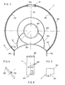
- Figure 1 is a plan view of the base member.
- Figure 2 is a section on II-II of Figure 1.
- Figure 3 is a plan view of the cover.
- FIG. 4 is a section on IV-IV of a detail in FIG. 3.
- Figure 5 is a plan view of a three-pin roll holder.
- Figure 6 is a section of Figure 5 along VI / VI.
- Figure 7 is a side and sectional view of a roll holder for a single roll.
- Figure 8 is a plan view of the lock.
- Figure 9 is a side view of the device preventing rotation of the roll holder when a roll is not empty.
- the preferred embodiment which we will describe comprises a base element 1 (fig. 1, 2) and a bowl-shaped cover 2 (fig. 3, 4) arranged so that they can be assembled quickly.
- the basic element 1 is in the form of a circular plate and it comprises the following elements: a first circular plate 101 surmounted on its periphery by a cylindrical wall 102 having on its upper peripheral edge four projections 103 directed towards the geometric center of the room. An annular surface 104 located at the same height as the upper edge of the cylindrical surface 102 ends in a second cylindrical wall 105.
- This cylindrical wall 105 has over approximately 3/4 of the periphery an extra thickness 106 in which a groove is formed 107 preferably of triangular section intended to receive and guide the corresponding edge of the cover 2.
- the cylindrical wall 105 extends beyond the annular surface 104 and forms a cylindrical wall 108
- the upper edge of the wall 108 is provided with regularly spaced L-shaped notches 109 which will be used to assemble the base element with the cover 2.
- the wall 108 is interrupted in a zone 110 provided for locking. from the distributor.
- the annular surface 104 also has four openings 111 provided in extra thicknesses or recesses 112 of the annular surface 104 intended for fixing the base element against a wall.
- the annular surface 104 also has a recess 113 intended to receive a plug-in device subsequently preventing the roller holder from rotating until a roller is not completely empty.
- the circular plate 101 has a housing 114 intended to receive a tongue 115 secured to a blade 116, the ends of which bear against two lugs 117 and 118, to form, in collaboration with notches 306 of the roller holder 3 (fig. 5 , 6) the latching device
- the plate 101 is also provided with a pin 119 intended to receive the roller holder for the use of the dispenser with a single roller of large diameter.
- the cover 2 (fig. 3, 4) is formed by a circular plate 201 having on one part a cutout 202 corresponding to the opening of the dispenser for the exit of the toilet paper and provided with two projections 203, 204 intended to facilitate the tearing of the paper.
- the plate 201 is provided on its inner face with reinforcing ribs 205, 206, as well as an opening 207 forming a window for visually controlling the quantity of paper available inside the dispenser.
- the window 207 is in principle closed by a transparent cover.
- the cylindrical wall 208 On the inner surface of the cylindrical wall 208 are arranged four pins 210 intended to collaborate with the notches 109 of the base element for a bayonet connection of the cover 2 with the base element.
- a housing 211 On the lateral surface opposite to the part 202 serving to open the dispenser, there is a housing 211 intended to house the lock which, after assembly of the dispenser, will ensure its locking to avoid inadvertent or unauthorized opening.
- the roller holder 3 comprises a circular plate 301 carrying three pins 302, arranged symmetrically, intended to support the rolls of toilet paper.
- the plate 301 is provided under its periphery with a flange 303 opposite the pins 302 and provided on its periphery with a circular rib 304.
- the diameter of the rib 304 is equal to or slightly less than the diameter of the plate 101 of the element basic.
- the rib 304 has a notch 305 of shape complementary to that of the projections 103 of the base element 1 to allow the positioning of the roller holder 3 in the housing formed by the base plate 101 and the cylindrical wall 102 of the 'basic element 1.
- the notch 305 is positioned opposite one of the projections 103 of the basic element and, taking advantage of the flexibility of the plate 301, it is slid under the projection 103 and the roller holder is rotated by 360 ° until the entire circular rib 304 passes under the four projections 103. From this moment, the roller holder cannot come out so untimely.
- you want to remove the roll holder you proceed in a similar way, that is to say, position the notch 305 facing one of the projections 103, the notch is brought out above the projection 103 and one begins to rotate the roller holder 3 by 360 ° until all of the rib 304 is above the projections 103.
- the rim 303 is provided with three notches 306, regularly spaced and intended to collaborate with the tongue 115 of the base element so that the roller holder stabilizes in a position when a spindle carrying a roller comes opposite the opening from the distributor.
- you want to rotate the roll holder simply press the spindle facing the dispenser opening clockwise, which advances the roller until it clicks into place. next, that is to say when the tongue 115 is in the next notch 306 of the roller holder.
- an L-shaped plug-in element 6 (fig. 9) has been provided. so that the part 602 comes to plug into the zone 113 of the base element and the part 601 projects towards the inside of the dispenser.
- the part 601 is dimensioned so that the roll holder cannot be turned 1/3 of a turn if a spindle 302 facing the opening of the dispenser still contains a roll with a few millimeters of paper. In this way, paper waste is avoided, the roll holder being able to be actuated only if a spindle contains practically no more paper.
- a sliding part 4 provided with a projection 401 intended to be inserted in the zone 110 of the base element 1 after the assembly of the cover on the base element for prevent disassembly by reverse rotation of the cover 2.
- the part 4 has on its upper part a head 402 located outside the housing 211 and serving as a limit stop during locking.
- the device is provided with a blocking system consisting of the following elements: on the surface of the lock 4 are provided three rectangular holes 403 intended to receive in the locked position three projections of corresponding shape and dimensions located at the end of the three elastic tabs integral with a wall of the housing 211 or of an attached part forming with the external wall 211a of the housing 211 drawer in which slides the lock 4.
- the locked position of the lock 4 that is to say when the head 402 bears against the housing 211, the three heads of the elastic tabs come into the three holes 403 preventing the lock 4 from sliding outside the housing 211 even if the head 402 is pulled hard.
- a key To be able to unlock, a key must be available in the form of a plate provided with e three spaced teeth corresponding to the three holes 403.
- the lateral surface 211a of the housing 211 has a rectangular window giving access to the three housings 403 both in the locked position of the lock 4 and in the open position thus allowing when the lock is blocked to introduce through this window the opening key to push the heads of the three tabs towards the inside of the dispenser and at the same time pull on the head 402 to obtain the unlocking and allow the cover 2 to be removed by turning it in the reverse direction of assembly to disengage the pins 210 from the notches 109 and be able to remove the cover.
- the dispenser for some reason must at some point be used with rollers of large diameters, i.e. use the dispenser with a single roll instead of three rollers as described above, remove the holder -rolls 3 as explained above and there is a part 5 comprising a pin 501 mounted at the end of an arm 502 provided with a cylindrical housing 503 intended to be fixed in the pin 119 of the part of the element base by a fixing device, for example a pin snap into the pin 119 or any other conventional means. In this way the spindle 501 comes approximately to the center of the plate 101 and the large diameter roller can be arranged.
- the articulation of the housing 503 on the pin 119 is made so that the part 502 can rotate around the swirl 119 thus pulling on the roller, the part 5 and in particular the spindle 501 tilts on the side where the paper is unwound and the roller will come to bear against the cylindrical surface 102 which will thus act as a brake on the large roller.
Landscapes
- Health & Medical Sciences (AREA)
- Public Health (AREA)
- Sanitary Thin Papers (AREA)
- Unwinding Webs (AREA)
- Winding Of Webs (AREA)
- Details Of Rigid Or Semi-Rigid Containers (AREA)
- Toilet Supplies (AREA)
- Containers And Packaging Bodies Having A Special Means To Remove Contents (AREA)
Claims (9)
- Spender für Toilettenpapier in Rollen, mit einem Grundelement (1), das Befestigungsmittel (111, 112) aufweist zur Befestigung an einer Wand, mit einem schüsselförmigen Deckel (2), der an seiner seitlichen Fläche eine Oeffnung zur Ausgabe des Papiers aufweist, und mit einem Rollenträger (3), wobei die seitliche Fläche des Deckels ein Gehäuse (211) aufweist, in dessen Inneren sich ein Riegel (4) befindet, welcher angeordnet ist um mit entsprechenden Mitteln (110) der seitlichen Fläche des Grundelements (1) zusammenzuwirken, um die Verriegelung des Spenders nach Zusammenbau des Deckels (2) auf dem Grundelement (1) zu gewährleisten, wobei das Gehäuse (211) und der Riegel (4) Entriegelungsmittel (403, 211a) aufweisen, die die Entriegelung nur mittels eines Schlüssels erlauben, und dadurch das ungewollte oder nicht erlaubte Abmontieren des Deckels (2) und des Grundelementes (1) verhindern, dadurch gekennzeichnet, dass das Grundelement (1) und die Schüssel (2) komplementäre Mittel aufweisen, die ihr schnelles Zusammenmontieren erlauben, dass der Rollenträger (3) eine Scheibe (301) ist, die wenigstens zwei symmetrisch angeordnete Spiesse (302) trägt, um die Rollen zu tragen und die in einem zylindrischen Gehäuse (101, 102) des Grundelements (1) montiert ist, dass das zylindrische Gehäuse (101, 102) an seinem oberen Rand wenigstens zwei zur zylindrischen Wand (102) senkrecht und nach dem Innern des Gehäuses gerichtete Vorsprünge aufweist, um das ungewollte Entweichen des Rollenträgers (3) zu verhindern, dass der besagte Rollenträger (3) an seinem Rand wenigstens einen Einschnitt (305) aufweist, dessen Form derjenigen der Vorsprünge (103) komplementär entspricht um den Zusammenbau des Rollenträgers (3) in dem zylindrischen Gehäuse (101, 102) sowie das Abmontieren zu gestatten.
- Spender nach Anspruch 1, dadurch gekennzeichnet, dass die Platte (101) des Grundelementes (1) eine Randrinne (107) aufweist, dessen Form derjenigen des oberen Randes (209) der Schüssel (2) entspricht, wobei die Randrinne zur Führung der Schüssel (2) beim Zusammenbau dient.
- Spender nach einem der Ansprüche 1 oder 2, dadurch gekennzeichnet, dass das Grundelement (1) in der Nähe seines Randes L-förmige Einschnitte (109) aufweist, um mit Vorsprüngen (210) zusammenzuwirken, welche auf der inneren Wand der seitlichen Fläche (208) der Schüssel (2) angeordnet sind, um einen schnellen, bajonettartigen Zusammenbau zu erlauben.
- Spender nach einem der Ansprüche 1 bis 3, dadurch gekennzeichnet, dass der Rollenträger zum Tragen von wenigstens zwei Rollen vorgesehen ist und dass er schwenkbar auf dem Grundelement montiert ist.
- Spender nach einem der Ansprüche 1 oder 4, dadurch gekennzeichnet, dass der Rollenträger (3) und das Grundelement (1) zusätzliche Mittel (306, 115) aufweisen, um das Indexieren des Rollenträgers (3) zu gestatten, damit der Rollenträger stoppt, wenn eine Papierrolle sich gegenüber der Oeffnung des Spenders befindet.
- Spender nach Anspruch 5, dadurch gekennzeichnet, dass die besagten Mittel (306, 115) eine Einklinkevorrichtung bilden.
- Spender nach einem der Ansprüche 3 bis 6, dadurch gekennzeichnet, dasss das Grundelement (1) einen Anschlag (6) aufweist, der das Drehen des Rollenträgers (3) verhindert, solange eine Rolle mit Toilettenpapier sich gegenüber der Oeffnung des Spenders befindet.
- Spender nach einem der Ansprüche 1 bis 7, dadurch gekennzeichnet, dass jeder Spiess (302) eine Vorrichtung aufweist, die das freie Drehen der Rolle des entsprechenden Spiesses des Rollenträgers verhindert.
- Spender nach einem der Ansprüche 1 bis 3, dadurch gekennzeichnet, dass der Spender eine einzige Papierrolle tragen kann und dass er aus einem Spiess (501) besteht, der senkrecht am Ende eines Armes (502) montiert ist, welcher an seinem anderen Ende um einen Zapfen (119) des Grundelements (1) artikuliert ist, welcher nach der Abnahme des Rollenträgers (3) erscheint.
Applications Claiming Priority (2)
| Application Number | Priority Date | Filing Date | Title |
|---|---|---|---|
| CH1657/90A CH683148A5 (fr) | 1990-05-16 | 1990-05-16 | Distributeur de papier hygiénique en rouleau. |
| CH1657/90 | 1990-05-16 |
Publications (2)
| Publication Number | Publication Date |
|---|---|
| EP0457731A1 EP0457731A1 (de) | 1991-11-21 |
| EP0457731B1 true EP0457731B1 (de) | 1993-10-20 |
Family
ID=4215583
Family Applications (1)
| Application Number | Title | Priority Date | Filing Date |
|---|---|---|---|
| EP91810360A Expired - Lifetime EP0457731B1 (de) | 1990-05-16 | 1991-05-10 | Spender für Toilettenpapierrollen |
Country Status (7)
| Country | Link |
|---|---|
| EP (1) | EP0457731B1 (de) |
| AT (1) | ATE95997T1 (de) |
| CH (1) | CH683148A5 (de) |
| DE (1) | DE69100521T2 (de) |
| DK (1) | DK0457731T3 (de) |
| ES (1) | ES2046879T3 (de) |
| PT (1) | PT8713T (de) |
Families Citing this family (1)
| Publication number | Priority date | Publication date | Assignee | Title |
|---|---|---|---|---|
| US6910579B2 (en) | 2002-05-28 | 2005-06-28 | Georgia-Pacific Corporation | Refillable flexible sheet dispenser |
Family Cites Families (6)
| Publication number | Priority date | Publication date | Assignee | Title |
|---|---|---|---|---|
| US3104844A (en) * | 1963-09-24 | Device for dispensing sheet material | ||
| CH599777A5 (de) * | 1976-12-17 | 1978-05-31 | Moelnlycke Gmbh | |
| BE880103A (fr) * | 1979-11-16 | 1980-03-17 | 2A S N C | Appareil pour le reglage automatique de l'extraction d'un materiau en rouleau, en particulier de papier absorbant pour essuie-mains |
| EP0103659A1 (de) * | 1982-09-16 | 1984-03-28 | Paperplan Hygiene Limited | Papierspender |
| NL8602194A (nl) * | 1986-08-28 | 1988-03-16 | Edet Nederland | Papierrolhouder. |
| DE3821176C2 (de) * | 1988-06-23 | 1999-06-10 | Feldmuehle Gmbh Scott | Halter für Papierrollen |
-
1990
- 1990-05-16 CH CH1657/90A patent/CH683148A5/fr not_active IP Right Cessation
-
1991
- 1991-05-10 ES ES199191810360T patent/ES2046879T3/es not_active Expired - Lifetime
- 1991-05-10 AT AT91810360T patent/ATE95997T1/de not_active IP Right Cessation
- 1991-05-10 DE DE91810360T patent/DE69100521T2/de not_active Expired - Fee Related
- 1991-05-10 DK DK91810360.7T patent/DK0457731T3/da not_active Application Discontinuation
- 1991-05-10 EP EP91810360A patent/EP0457731B1/de not_active Expired - Lifetime
-
1993
- 1993-02-26 PT PT8713U patent/PT8713T/pt not_active Application Discontinuation
Also Published As
| Publication number | Publication date |
|---|---|
| PT8713T (pt) | 1993-08-31 |
| DE69100521D1 (de) | 1993-11-25 |
| DK0457731T3 (da) | 1994-03-07 |
| ES2046879T3 (es) | 1994-02-01 |
| EP0457731A1 (de) | 1991-11-21 |
| ATE95997T1 (de) | 1993-11-15 |
| DE69100521T2 (de) | 1994-05-11 |
| CH683148A5 (fr) | 1994-01-31 |
Similar Documents
| Publication | Publication Date | Title |
|---|---|---|
| FR2721060A1 (fr) | Loquet à levier avec patte ayant une action d'éjection. | |
| FR2680162A1 (fr) | Ensemble indicateur pour boite aux lettres. | |
| WO2010003637A1 (fr) | Element de fermeture d'un recipient en particulier fait dans un materiau de type feuille | |
| FR2544296A1 (fr) | Enrouleur portable pour tuyauterie souple, notamment pour vehicules automobiles, caravanes, autobus, bateaux, terrasses et petits jardins | |
| WO1996006557A1 (fr) | Appareil distributeur de materiaux d'essuyage pouvant etre distribues sous forme pliee ou non pliee | |
| EP1593780B1 (de) | Verriegelungsvorrichtung für Schachtrahmen | |
| WO1995026157A1 (fr) | Appareil distributeur de materiaux d'essuyage pouvant etre distribues sous forme pliee ou non pliee | |
| CA2215450A1 (fr) | Dispositif de chargement pour appareil distributeur de materiaux d'essuyage | |
| FR2703578A1 (fr) | Charnière pour le montage d'un ensemble siège-couvercle sur une cuvette de cabinet. | |
| EP0457731B1 (de) | Spender für Toilettenpapierrollen | |
| EP1910626B2 (de) | Vorrichtung zur gelenksverbindung eines stopfens oder deckels mit einem rahmen, v.a. eines mannloches | |
| EP3046453B1 (de) | Spender für vorgeschnittenes, aufgerolltes bahnmaterial mit horizontal oder vertikal positionierter rollspule | |
| EP1463431A1 (de) | Vorrichtung zur steuerung und neupositionierung einer wischmaterialrolle in einem automatischen schneidspender | |
| EP1117320B1 (de) | Abwischmaterialspender mit frontaler spulenposition | |
| EP0681066B1 (de) | Vorrichtung zur gelenkigen Verbindung eines Deckels auf einem Rahmen, nämlich zum Schliessen einer Öffnung in einer Fahrbahn | |
| BE1010326A3 (fr) | Dispositif de rangement pour support d'informations. | |
| EP0060794A2 (de) | Papierkorb | |
| EP0511130B1 (de) | Drehbare Durchfahrtsperre | |
| EP1106774A1 (de) | Vorrichtung zum Fixieren eines Antriebs, und Betätigungsmechanismus einer Schliess- oder Sonnenschutzeinrichtung mit solcher Vorrichtung | |
| FR2615024A1 (fr) | Dispositif de support d'information, notamment publicitaire, pour chariot de supermarche | |
| EP0657129B1 (de) | Geschirr wie ein Tablett, Untertasse oder Teller für die Presentation einer Rechnung | |
| FR2629856A1 (de) | ||
| FR2504797A1 (fr) | Siege water-closet | |
| FR2630169A1 (fr) | Installation pour l'amenagement amovible et verrouillable de tout mobilier | |
| EP0038253B1 (de) | Alarmgehäuse |
Legal Events
| Date | Code | Title | Description |
|---|---|---|---|
| PUAI | Public reference made under article 153(3) epc to a published international application that has entered the european phase |
Free format text: ORIGINAL CODE: 0009012 |
|
| AK | Designated contracting states |
Kind code of ref document: A1 Designated state(s): AT BE DE DK ES FR GB IT NL SE |
|
| 17P | Request for examination filed |
Effective date: 19920226 |
|
| 17Q | First examination report despatched |
Effective date: 19920707 |
|
| GRAA | (expected) grant |
Free format text: ORIGINAL CODE: 0009210 |
|
| AK | Designated contracting states |
Kind code of ref document: B1 Designated state(s): AT BE DE DK ES FR GB IT NL SE |
|
| REF | Corresponds to: |
Ref document number: 95997 Country of ref document: AT Date of ref document: 19931115 Kind code of ref document: T |
|
| REF | Corresponds to: |
Ref document number: 69100521 Country of ref document: DE Date of ref document: 19931125 |
|
| ITF | It: translation for a ep patent filed | ||
| GBT | Gb: translation of ep patent filed (gb section 77(6)(a)/1977) |
Effective date: 19931213 |
|
| REG | Reference to a national code |
Ref country code: ES Ref legal event code: FG2A Ref document number: 2046879 Country of ref document: ES Kind code of ref document: T3 |
|
| REG | Reference to a national code |
Ref country code: DK Ref legal event code: T3 |
|
| PGFP | Annual fee paid to national office [announced via postgrant information from national office to epo] |
Ref country code: AT Payment date: 19940516 Year of fee payment: 4 |
|
| PGFP | Annual fee paid to national office [announced via postgrant information from national office to epo] |
Ref country code: SE Payment date: 19940517 Year of fee payment: 4 |
|
| PGFP | Annual fee paid to national office [announced via postgrant information from national office to epo] |
Ref country code: NL Payment date: 19940531 Year of fee payment: 4 |
|
| PLBE | No opposition filed within time limit |
Free format text: ORIGINAL CODE: 0009261 |
|
| 26N | No opposition filed | ||
| EAL | Se: european patent in force in sweden |
Ref document number: 91810360.7 |
|
| PG25 | Lapsed in a contracting state [announced via postgrant information from national office to epo] |
Ref country code: AT Effective date: 19950510 |
|
| PG25 | Lapsed in a contracting state [announced via postgrant information from national office to epo] |
Ref country code: SE Effective date: 19950511 |
|
| PG25 | Lapsed in a contracting state [announced via postgrant information from national office to epo] |
Ref country code: NL Effective date: 19951201 |
|
| NLV4 | Nl: lapsed or anulled due to non-payment of the annual fee |
Effective date: 19951201 |
|
| EUG | Se: european patent has lapsed |
Ref document number: 91810360.7 |
|
| PGFP | Annual fee paid to national office [announced via postgrant information from national office to epo] |
Ref country code: FR Payment date: 19990421 Year of fee payment: 9 |
|
| PGFP | Annual fee paid to national office [announced via postgrant information from national office to epo] |
Ref country code: DE Payment date: 19990424 Year of fee payment: 9 |
|
| PGFP | Annual fee paid to national office [announced via postgrant information from national office to epo] |
Ref country code: GB Payment date: 19990512 Year of fee payment: 9 Ref country code: DK Payment date: 19990512 Year of fee payment: 9 |
|
| PGFP | Annual fee paid to national office [announced via postgrant information from national office to epo] |
Ref country code: ES Payment date: 19990524 Year of fee payment: 9 |
|
| PGFP | Annual fee paid to national office [announced via postgrant information from national office to epo] |
Ref country code: BE Payment date: 19990728 Year of fee payment: 9 |
|
| PG25 | Lapsed in a contracting state [announced via postgrant information from national office to epo] |
Ref country code: GB Free format text: LAPSE BECAUSE OF NON-PAYMENT OF DUE FEES Effective date: 20000510 Ref country code: DK Free format text: LAPSE BECAUSE OF NON-PAYMENT OF DUE FEES Effective date: 20000510 |
|
| PG25 | Lapsed in a contracting state [announced via postgrant information from national office to epo] |
Ref country code: ES Free format text: THE PATENT HAS BEEN ANNULLED BY A DECISION OF A NATIONAL AUTHORITY Effective date: 20000511 |
|
| PG25 | Lapsed in a contracting state [announced via postgrant information from national office to epo] |
Ref country code: BE Free format text: LAPSE BECAUSE OF NON-PAYMENT OF DUE FEES Effective date: 20000531 |
|
| BERE | Be: lapsed |
Owner name: S.A. STEINER CY INTERNATIONAL Effective date: 20000531 |
|
| GBPC | Gb: european patent ceased through non-payment of renewal fee |
Effective date: 20000510 |
|
| REG | Reference to a national code |
Ref country code: DK Ref legal event code: EBP |
|
| PG25 | Lapsed in a contracting state [announced via postgrant information from national office to epo] |
Ref country code: FR Free format text: LAPSE BECAUSE OF NON-PAYMENT OF DUE FEES Effective date: 20010131 |
|
| PG25 | Lapsed in a contracting state [announced via postgrant information from national office to epo] |
Ref country code: DE Free format text: LAPSE BECAUSE OF NON-PAYMENT OF DUE FEES Effective date: 20010301 |
|
| REG | Reference to a national code |
Ref country code: FR Ref legal event code: ST |
|
| REG | Reference to a national code |
Ref country code: ES Ref legal event code: FD2A Effective date: 20020304 |
|
| PG25 | Lapsed in a contracting state [announced via postgrant information from national office to epo] |
Ref country code: IT Free format text: LAPSE BECAUSE OF NON-PAYMENT OF DUE FEES;WARNING: LAPSES OF ITALIAN PATENTS WITH EFFECTIVE DATE BEFORE 2007 MAY HAVE OCCURRED AT ANY TIME BEFORE 2007. THE CORRECT EFFECTIVE DATE MAY BE DIFFERENT FROM THE ONE RECORDED. Effective date: 20050510 |