EP0457399B1 - Wärme-Kraft-System mit Stirling-Motor - Google Patents
Wärme-Kraft-System mit Stirling-Motor Download PDFInfo
- Publication number
- EP0457399B1 EP0457399B1 EP91201114A EP91201114A EP0457399B1 EP 0457399 B1 EP0457399 B1 EP 0457399B1 EP 91201114 A EP91201114 A EP 91201114A EP 91201114 A EP91201114 A EP 91201114A EP 0457399 B1 EP0457399 B1 EP 0457399B1
- Authority
- EP
- European Patent Office
- Prior art keywords
- engine
- heat exchanger
- cogeneration system
- heat
- cooling
- Prior art date
- Legal status (The legal status is an assumption and is not a legal conclusion. Google has not performed a legal analysis and makes no representation as to the accuracy of the status listed.)
- Expired - Lifetime
Links
Images


Classifications
-
- F—MECHANICAL ENGINEERING; LIGHTING; HEATING; WEAPONS; BLASTING
- F02—COMBUSTION ENGINES; HOT-GAS OR COMBUSTION-PRODUCT ENGINE PLANTS
- F02G—HOT GAS OR COMBUSTION-PRODUCT POSITIVE-DISPLACEMENT ENGINE PLANTS; USE OF WASTE HEAT OF COMBUSTION ENGINES; NOT OTHERWISE PROVIDED FOR
- F02G1/00—Hot gas positive-displacement engine plants
- F02G1/04—Hot gas positive-displacement engine plants of closed-cycle type
- F02G1/043—Hot gas positive-displacement engine plants of closed-cycle type the engine being operated by expansion and contraction of a mass of working gas which is heated and cooled in one of a plurality of constantly communicating expansible chambers, e.g. Stirling cycle type engines
- F02G1/053—Component parts or details
-
- F—MECHANICAL ENGINEERING; LIGHTING; HEATING; WEAPONS; BLASTING
- F02—COMBUSTION ENGINES; HOT-GAS OR COMBUSTION-PRODUCT ENGINE PLANTS
- F02G—HOT GAS OR COMBUSTION-PRODUCT POSITIVE-DISPLACEMENT ENGINE PLANTS; USE OF WASTE HEAT OF COMBUSTION ENGINES; NOT OTHERWISE PROVIDED FOR
- F02G1/00—Hot gas positive-displacement engine plants
- F02G1/04—Hot gas positive-displacement engine plants of closed-cycle type
- F02G1/043—Hot gas positive-displacement engine plants of closed-cycle type the engine being operated by expansion and contraction of a mass of working gas which is heated and cooled in one of a plurality of constantly communicating expansible chambers, e.g. Stirling cycle type engines
- F02G1/044—Hot gas positive-displacement engine plants of closed-cycle type the engine being operated by expansion and contraction of a mass of working gas which is heated and cooled in one of a plurality of constantly communicating expansible chambers, e.g. Stirling cycle type engines having at least two working members, e.g. pistons, delivering power output
-
- F—MECHANICAL ENGINEERING; LIGHTING; HEATING; WEAPONS; BLASTING
- F02—COMBUSTION ENGINES; HOT-GAS OR COMBUSTION-PRODUCT ENGINE PLANTS
- F02G—HOT GAS OR COMBUSTION-PRODUCT POSITIVE-DISPLACEMENT ENGINE PLANTS; USE OF WASTE HEAT OF COMBUSTION ENGINES; NOT OTHERWISE PROVIDED FOR
- F02G1/00—Hot gas positive-displacement engine plants
- F02G1/04—Hot gas positive-displacement engine plants of closed-cycle type
- F02G1/043—Hot gas positive-displacement engine plants of closed-cycle type the engine being operated by expansion and contraction of a mass of working gas which is heated and cooled in one of a plurality of constantly communicating expansible chambers, e.g. Stirling cycle type engines
- F02G1/045—Controlling
- F02G1/05—Controlling by varying the rate of flow or quantity of the working gas
-
- F—MECHANICAL ENGINEERING; LIGHTING; HEATING; WEAPONS; BLASTING
- F02—COMBUSTION ENGINES; HOT-GAS OR COMBUSTION-PRODUCT ENGINE PLANTS
- F02G—HOT GAS OR COMBUSTION-PRODUCT POSITIVE-DISPLACEMENT ENGINE PLANTS; USE OF WASTE HEAT OF COMBUSTION ENGINES; NOT OTHERWISE PROVIDED FOR
- F02G1/00—Hot gas positive-displacement engine plants
- F02G1/04—Hot gas positive-displacement engine plants of closed-cycle type
- F02G1/043—Hot gas positive-displacement engine plants of closed-cycle type the engine being operated by expansion and contraction of a mass of working gas which is heated and cooled in one of a plurality of constantly communicating expansible chambers, e.g. Stirling cycle type engines
- F02G1/053—Component parts or details
- F02G1/055—Heaters or coolers
-
- F—MECHANICAL ENGINEERING; LIGHTING; HEATING; WEAPONS; BLASTING
- F02—COMBUSTION ENGINES; HOT-GAS OR COMBUSTION-PRODUCT ENGINE PLANTS
- F02G—HOT GAS OR COMBUSTION-PRODUCT POSITIVE-DISPLACEMENT ENGINE PLANTS; USE OF WASTE HEAT OF COMBUSTION ENGINES; NOT OTHERWISE PROVIDED FOR
- F02G5/00—Profiting from waste heat of combustion engines, not otherwise provided for
- F02G5/02—Profiting from waste heat of exhaust gases
- F02G5/04—Profiting from waste heat of exhaust gases in combination with other waste heat from combustion engines
-
- F—MECHANICAL ENGINEERING; LIGHTING; HEATING; WEAPONS; BLASTING
- F24—HEATING; RANGES; VENTILATING
- F24D—DOMESTIC- OR SPACE-HEATING SYSTEMS, e.g. CENTRAL HEATING SYSTEMS; DOMESTIC HOT-WATER SUPPLY SYSTEMS; ELEMENTS OR COMPONENTS THEREFOR
- F24D18/00—Small-scale combined heat and power [CHP] generation systems specially adapted for domestic heating, space heating or domestic hot-water supply
-
- F—MECHANICAL ENGINEERING; LIGHTING; HEATING; WEAPONS; BLASTING
- F24—HEATING; RANGES; VENTILATING
- F24D—DOMESTIC- OR SPACE-HEATING SYSTEMS, e.g. CENTRAL HEATING SYSTEMS; DOMESTIC HOT-WATER SUPPLY SYSTEMS; ELEMENTS OR COMPONENTS THEREFOR
- F24D5/00—Hot-air central heating systems; Exhaust gas central heating systems
-
- F—MECHANICAL ENGINEERING; LIGHTING; HEATING; WEAPONS; BLASTING
- F02—COMBUSTION ENGINES; HOT-GAS OR COMBUSTION-PRODUCT ENGINE PLANTS
- F02G—HOT GAS OR COMBUSTION-PRODUCT POSITIVE-DISPLACEMENT ENGINE PLANTS; USE OF WASTE HEAT OF COMBUSTION ENGINES; NOT OTHERWISE PROVIDED FOR
- F02G2254/00—Heat inputs
- F02G2254/30—Heat inputs using solar radiation
-
- F—MECHANICAL ENGINEERING; LIGHTING; HEATING; WEAPONS; BLASTING
- F02—COMBUSTION ENGINES; HOT-GAS OR COMBUSTION-PRODUCT ENGINE PLANTS
- F02G—HOT GAS OR COMBUSTION-PRODUCT POSITIVE-DISPLACEMENT ENGINE PLANTS; USE OF WASTE HEAT OF COMBUSTION ENGINES; NOT OTHERWISE PROVIDED FOR
- F02G2254/00—Heat inputs
- F02G2254/60—Heat inputs using air preheaters
-
- F—MECHANICAL ENGINEERING; LIGHTING; HEATING; WEAPONS; BLASTING
- F02—COMBUSTION ENGINES; HOT-GAS OR COMBUSTION-PRODUCT ENGINE PLANTS
- F02G—HOT GAS OR COMBUSTION-PRODUCT POSITIVE-DISPLACEMENT ENGINE PLANTS; USE OF WASTE HEAT OF COMBUSTION ENGINES; NOT OTHERWISE PROVIDED FOR
- F02G2256/00—Coolers
- F02G2256/50—Coolers with coolant circulation
-
- F—MECHANICAL ENGINEERING; LIGHTING; HEATING; WEAPONS; BLASTING
- F02—COMBUSTION ENGINES; HOT-GAS OR COMBUSTION-PRODUCT ENGINE PLANTS
- F02G—HOT GAS OR COMBUSTION-PRODUCT POSITIVE-DISPLACEMENT ENGINE PLANTS; USE OF WASTE HEAT OF COMBUSTION ENGINES; NOT OTHERWISE PROVIDED FOR
- F02G2260/00—Recuperating heat from exhaust gases of combustion engines and heat from cooling circuits
-
- F—MECHANICAL ENGINEERING; LIGHTING; HEATING; WEAPONS; BLASTING
- F02—COMBUSTION ENGINES; HOT-GAS OR COMBUSTION-PRODUCT ENGINE PLANTS
- F02G—HOT GAS OR COMBUSTION-PRODUCT POSITIVE-DISPLACEMENT ENGINE PLANTS; USE OF WASTE HEAT OF COMBUSTION ENGINES; NOT OTHERWISE PROVIDED FOR
- F02G2270/00—Constructional features
- F02G2270/20—Plural piston swash plates
-
- F—MECHANICAL ENGINEERING; LIGHTING; HEATING; WEAPONS; BLASTING
- F02—COMBUSTION ENGINES; HOT-GAS OR COMBUSTION-PRODUCT ENGINE PLANTS
- F02G—HOT GAS OR COMBUSTION-PRODUCT POSITIVE-DISPLACEMENT ENGINE PLANTS; USE OF WASTE HEAT OF COMBUSTION ENGINES; NOT OTHERWISE PROVIDED FOR
- F02G2280/00—Output delivery
- F02G2280/20—Rotary generators
-
- F—MECHANICAL ENGINEERING; LIGHTING; HEATING; WEAPONS; BLASTING
- F24—HEATING; RANGES; VENTILATING
- F24D—DOMESTIC- OR SPACE-HEATING SYSTEMS, e.g. CENTRAL HEATING SYSTEMS; DOMESTIC HOT-WATER SUPPLY SYSTEMS; ELEMENTS OR COMPONENTS THEREFOR
- F24D2101/00—Electric generators of small-scale CHP systems
- F24D2101/80—Electric generators driven by external combustion engines, e.g. Stirling engines
-
- F—MECHANICAL ENGINEERING; LIGHTING; HEATING; WEAPONS; BLASTING
- F24—HEATING; RANGES; VENTILATING
- F24D—DOMESTIC- OR SPACE-HEATING SYSTEMS, e.g. CENTRAL HEATING SYSTEMS; DOMESTIC HOT-WATER SUPPLY SYSTEMS; ELEMENTS OR COMPONENTS THEREFOR
- F24D2103/00—Thermal aspects of small-scale CHP systems
- F24D2103/10—Small-scale CHP systems characterised by their heat recovery units
- F24D2103/13—Small-scale CHP systems characterised by their heat recovery units characterised by their heat exchangers
-
- Y—GENERAL TAGGING OF NEW TECHNOLOGICAL DEVELOPMENTS; GENERAL TAGGING OF CROSS-SECTIONAL TECHNOLOGIES SPANNING OVER SEVERAL SECTIONS OF THE IPC; TECHNICAL SUBJECTS COVERED BY FORMER USPC CROSS-REFERENCE ART COLLECTIONS [XRACs] AND DIGESTS
- Y02—TECHNOLOGIES OR APPLICATIONS FOR MITIGATION OR ADAPTATION AGAINST CLIMATE CHANGE
- Y02E—REDUCTION OF GREENHOUSE GAS [GHG] EMISSIONS, RELATED TO ENERGY GENERATION, TRANSMISSION OR DISTRIBUTION
- Y02E20/00—Combustion technologies with mitigation potential
- Y02E20/14—Combined heat and power generation [CHP]
-
- Y—GENERAL TAGGING OF NEW TECHNOLOGICAL DEVELOPMENTS; GENERAL TAGGING OF CROSS-SECTIONAL TECHNOLOGIES SPANNING OVER SEVERAL SECTIONS OF THE IPC; TECHNICAL SUBJECTS COVERED BY FORMER USPC CROSS-REFERENCE ART COLLECTIONS [XRACs] AND DIGESTS
- Y02—TECHNOLOGIES OR APPLICATIONS FOR MITIGATION OR ADAPTATION AGAINST CLIMATE CHANGE
- Y02T—CLIMATE CHANGE MITIGATION TECHNOLOGIES RELATED TO TRANSPORTATION
- Y02T10/00—Road transport of goods or passengers
- Y02T10/10—Internal combustion engine [ICE] based vehicles
- Y02T10/12—Improving ICE efficiencies
Definitions
- the present invention relates to a cogeneration system and more particularly to a cogeneration system employing a Stirling cycle engine for driving an electric generator wherein the "waste" heat is used to provide space heating or hot water service.
- Cogeneration is a process whereby a consumer in need of either hot water and/or heat for a residence or a small business, instead of merely burning fuel to produce heat, can burn fuel to drive an electric generator and utilize the cycle heat and the waste heat from the drive means, generator and exhaust to produce the needed hot water or hot air.
- the electricity generated can be used on site with any surplus electric energy directed to the utility's electric grid and sold to the utility. Numerous efficiencies can be achieved with such a cogeneration system.
- thermodynamics states that the quality of energy can change only in one direction, energy losses its capacity to do useful work, ultimately reaching the point of zero usefulness. As available work is consumed, the quality of energy is degraded, however, the quantity of energy remains the same. Hence, good energy saving practice strives to harness energy of the highest quality possible, that is to avoid unwanted degradation.
- the Stirling cycle engine is well suited for cogeneration applications. This is due in part to qualities of the Stirling engine such as quiet running, primary heat rejection by cooling water, long life, low emissions, and low maintenance.
- the invention relates to a cogeneration system as described in the pre-characterising part of claim 1.
- EP-A-0268726 describes a cogeneration system comprising an engine and a generator driven by said engine.
- the engine and the generator are cooled by a cooling liquid which is circulated through a heat exchanger.
- a latent heat recovery apparatus including a vessel wherein water is supplied and showered at the upper end of said vessel. Exhausted gas from a gas engine is introduced into the lower end of said vessel to heat the water in direct contact with the water in order to produce warm water by recovering the latent heat of the exhausted gas.
- the invention is characterised by the measures mentioned in the characterising part of claim 1.
- Stirling engines may be powered directly by any source of heat such as from solar energy sources, combusted gases, liquid fuels, solid fuels etc.
- the preferred type of Stirling engine for use in small cogeneration systems incorporates multiple gas combustors that are integrated into the structure of the engine to provide a compact and efficient energy conversion machine. This system eliminates the requirement of a separate heat pipe or other heat transport systems for transferring heat from a remote source. Individual combustors are provided for each cylinder of a multiple cylinder Stirling engine.
- the output shaft of the Stirling engine is coupled to an electric generator to drive the generator.
- the generator is enclosed in the pressure hull of the engine reducing the complexity of the drive shaft coupling and seals.
- the electric power generated is consumed on the premises with any surplus electric energy being fed to the electric grid and sold to the local utility.
- the engine and generator are cooled by cooling water.
- the water is further heated in a condensing heat exchanger by the hot engine exhaust gases.
- the hot water is then used for space heating or to provide hot water service to the building.
- the water can be fed to hot water radiators or used to heat air for forced air space heating.
- an air conditioner can be included with the cogeneration system with the electricity produced used to power the air conditioning compressor.
- the cooling water is routed to a radiator outside of the building for rejection of waste heat from the Stirling engine and generator.
- a cogeneration system In addition to providing more efficient use of fuels, a cogeneration system also reduces CO2 emissions. Coal combustion, often used for producing electric energy at a power plant, produces much more CO2 than natural gas combustion that is most often burned for residential and light commercial building heating purposes. Thus, electricity produced by cogeneration will reduce the amount of CO2 emissions. Furthermore, since the electricity can be used at or near its site of production, transmission line losses can be reduced. This reduces the amount of electric power which must be generated, thereby reducing the amount of fuel burned and emissions produced.
- Figure 1 is a longitudinal, partially cross sectional and partially elevational view of a Stirling engine with integrated gas combustors and an electric generator in accordance with this invention.
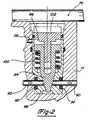
- Figure 2 is an enlarged cross sectional view of the short circuit valve assembly shown in Figure 1;
- Figure 3 is a schematic view of a hot water cogeneration system
- Figure 4 is a graph showing electric energy production, hot water production and electric energy efficiency of the cogeneration system shown in Figure 3;
- Figure 5 is a schematic of a cogeneration system used for producing hot water for space heating
- Figure 6 is a schematic of cogeneration system for use in providing forced air for space heating.
- Figure 7 is a modification of the cogeneration system of Figure 6 in which an air conditioning system has been included.
- Engine 10 includes four substantially parallel piston cylinders 12 which are disposed in a square cluster about a central axis within drive mechanism housing 14. Associated with each piston cylinder 12 and located on an end surface of drive mechanism housing 14 are heat transfer stacks 15 comprising cooler 16, regenerator 18, and heat exchanger 20. Cooler 16, regenerator 18, and heat exchanger 20 are arranged end-to-end to form a cylindrical column. Each heat exchanger 20 communicates with a separate piston cylinder 12 by one of four connecting ducts 22 each connected to one end of a cylinder 12. The other end of each cylinder 12 is connected to a cooler 16 of another of the four heat stacks 15 by duct 21.
- each piston cylinder 12 Located within each piston cylinder 12 is a movable piston 24 and a connecting rod 26 rigidly fixed thereto. Connecting rods 26 are attached to swashplate 28 to convert the reciprocating axial motion of pistons 24 to rotary motion of output shaft 30. Output shaft 30 is coupled to an electric generator 32 to drive the generator. Generator 32 is enclosed in the pressure hull 34 of the Stirling engine. Pressure hull 34 and drive mechanism housing 14 are cooled by water circulating around the pressure hull within water jacket 36.
- Heat is inputted to Stirling engine 10 through separate combustor assemblies 40 associated with each of the heat exchangers 20.
- heat exchangers 20 are comprised of a plurality of relatively thin and flexible tubes 42 through which the working fluid, such as helium or hydrogen of Stirling engine 10 flows.
- the working fluid flowing through tubes 42 collects at annular manifold 44 which communicates with connecting duct 22.
- Each combustor assembly 40 includes a combustion chamber tube 46 which has a plurality of air inlets 48.
- a combustible gas is introduced into combustion chamber tubes 46 through gas nozzles 50.
- Air inlets 48 and gas nozzles 50 are designed to provide a highly turbulent combustible gas flow within combustion chamber tubes 46 which provides for efficient and clean combustion.
- Ignition plug 52 is provided to initiate combustion.
- the Stirling engine working fluid within heat exchanger 20 expands due to the heat. This increases the pressure in ducts 22 and cylinder 12 to force piston 24 toward swashplate 28. As the pistons move, they displace working fluid from coolers 16 through regenerators 18 to heat exchanger 20 in an adjacent heat transfer stack 15.
- Heat exchanger wall 54 surrounds engine 10 and serves to confine hot gases from combustion chamber tubes 46 within exchangers 20. Radially outside of wall 54 are counterflow heat exchangers 56. As shown by the phantom line arrows 57, exhaust gases are permitted to flow through heat exchangers 56 and escape between walls 54 and 58. Inlet air also passes through heat exchangers 56 from air inlet 60 formed between annular walls 58 and 62 as shown by full line arrows 63. The counterflow heat exchangers 56 thus serve as a preheater to heat inlet air with the hot exhaust gases to provide enhanced thermal efficiency of engine 10.
- the region between wall 62 and outer housing 64 is packed with a thermal insulating material 66.
- the exhaust gases are collected in a manifold and directed to a condensing heat exchangers where the heat is transferred to the engine cooling water.
- the cooled exhaust gases are then exhausted from the building in which the cogeneration system is installed. This will be described in greater detail below.
- the Stirling engine is provided with an exhaust bypass valve 80 to direct the hot combustion gases directly to the condensing heat exchanger without first preheating the intake combustion air.
- Bypass valve 80 is disposed in exhaust outlet 82. When valve 80 is opened, hot exhaust gases from heat exchangers 20 flow through exhaust outlet 82 as indicated by the phantom line arrows 84.
- By-pass valve 80 can be regulated at any position between fully open and fully closed to regulate the heat supplied to the water depending on the heat demand.
- Swashplate housing 36 contains lubricating oil for the swashplate and drive mechanism.
- the lubricating oil is sealed from the piston cylinders 12 by cap seal assemblies 68 at the end of the piston cylinders 12.
- Oil pump module 70 houses a lubrication oil pump that is directly driven by the engine shaft. Internal passages direct the oil to galleries to provide lubrication of the drive mechanism moving parts.
- Stirling engine 10 is started by operating generator 32 as a motor to drive engine shaft 30.
- Stirling engine 10 includes a short circuit valve assembly 76 which is used to connect the lower portions 78 of piston cylinders 12 with one another. With the cylinders connected, as pistons 24 are moved, there is no compression of the working gas. Details of short circuit valve assembly 76 are shown in the enlarged view of Figure 2.
- Valve assembly 76 includes valve seat housing 88 through which passes four conduits 90 leading to lower portion 78 of each cylinder 12.
- the conduits 90 intersect one another at the center of valve seat housing 88.
- O-ring seals 92 around conduits 90 seal the juncture of valve seat housing 88 with drive mechanism housing 14 to prevent loss of the Stirling engine working gas.
- Valve member 94 is shown in the seated position in which valve member 94 closes the intersection of the conduits 90 to separate each cylinder 12 from one another. After the engine has been warmed to from one another. After the engine has been warmed to operating temperature, valve member 94 is held in the closed position by lubricating oil in chamber 96 from oil passage 98.
- spring 100 moves valve member 94 against valve support 102 to open conduits 90 until the engine is started again.
- Spring 100 has a spring rate so that engine 10 will be heated to operating temperature when the oil pressure in chamber 96 is sufficient to close valve 76.
- Coolers 16 include a plurality of cooling tubes (not shown) similar to tubes 42 in heaters 20, through which the engine working fluid passes.
- the cooling tubes are connected to the lower portion 78 of a cylinder 12 by ducts 21.
- Engine cooling water circulates through coolers 16 around pipes 43 to remove heat from the working fluid. Cooling water enters the engine and generator through fitting 35 in water jacket 36.
- FIG. 3 shows a schematic of a cogeneration system 110 according to the present invention used to produce hot water.
- the exhaust gases from engine 10 are directed through exhaust pipe 122, condensing heat exchanger 118 and to a chimney or other outlet.
- the engine and generator 32 are cooled by a cooling liquid, in this case water, which enters the engine and generator through inlet 123.
- the water is warmed by the engine and generator and leaves the engine through pipe 124.
- the water is further heated in heat exchanger 118 by the engine exhaust gases. Once heated, the water flows through pipe 126 to storage tank 128 for use as hot water when needed.
- Stirling engine 10 is operated with a mean temperature of heat exchangers 20 of 800°C.
- the coolers 16 are maintained at a mean temperature of 80°C.
- the engine size is determined such that the "waste" heat from the Stirling cycle, friction, generator and exhaust is sufficient to provide the needed heat under peak conditions.
- a single size engine can be used in a standard cogeneration package with the engine working fluid mean pressure set at different values to vary the heat output depending on heating need.
- the efficiency of cogeneration system 110 is shown by the following example. Studies indicate that a small commercial building, such as a modest restaurant, needs about 19305 l (5100 gallons) of hot water per day with a temperature rise of 29°C (85°F). This requires a heat input of 42kW thermal. Calculations have been made using a Stirling engine such as engine 10 shown in Figure 1 having four cylinders, each with a 120cm3 swept volume. The following parameters were kept constant:
- Q tot 10.35kW th
- an additional 8.8kW th is delivered to the hot water in the heat exchanger.
- Figure 4 is a graph showing the electric energy, hot water heat and energy efficiency for various mean pressures of the engine working gas.
- the electric energy produced is shown by line 202.
- Electric energy output increases with increased mean pressure.
- Solid line 204 represents the thermal energy delivered to the hot water with by-pass valve 80 closed i.e. with the intake air being preheated. When extra hot water is needed, by-pass valve 80 is opened and the energy delivered to the hot water increases, as shown by broken line 206.
- Solid line 208 represents the efficiency of electric energy production with by-pass valve 80 closed while broken line 210 represents the electric energy production efficiency with valve 80 open. With the by-pass value open, the heat to the hot water is increased while the efficiency is decreased.
- FIG. 5 illustrates a cogeneration system 112 which is similar to system 110.
- System 112 is used to produce hot water for space heating.
- System 112 eliminates water storage tank 128 and instead, directs the hot water from heat exchanger outlet pipe 126 to water fed radiators (not shown) for space heating.
- Cold water is returned from the radiators to engine 10 by cold water return pipe 132.
- FIG. 6 illustrates cogeneration system 114 in which the hot water is used to heat air for forced air space heating.
- Outlet pipe 126 directs the hot water to a water to air heat exchanger 133.
- Heat exchanger 133 is disposed in an air outlet duct 135 from blower 137.
- Blower inlet duct 139 supplies fresh air and/or cold return air form the space being heated. Air from the blower passes through heat exchanger 133 to warm the air for space heating. The water, once cooled in heat exchanger 133, returns to engine 10 through pipe 141.
- System 114 can be modified as shown by cogeneration system 116 in Figure 7 to include air conditioning for use during the summer.
- system 116 during winter, when space heating is required, the system functions identically to cogeneration system 114 described with respect to Figure 6.
- a one way check valve 172 is included in pipe 126 to ensure proper flow direction in the pipe.
- an air conditioning compressor 150 is installed outside of the building in which the Stirling engine, generator and air blower are installed.
- a refrigerant, typically Freon, is conveyed from compressor 150 through conduit 152 to a refrigerant heat exchanger 154 in the blower outlet duct 135. The refrigerant is returned through conduit 156 to compressor 150.
- Heat exchanger 154 is thus used to cool air from blower 137 to provide cool air for air conditioning.
- Valve 156 in water pipe 124 is used to direct cooling water to radiator 160 located outside of the building through pipe 162.
- Return pipe 164 directs the water back to return pipe 141 through valve 158.
- Radiator 160 is used to remove heat from the engine coolant water and is cooled by a fan 166 driven by electric motor 168.
- compressor 150 and motor 168 are powered by electricity produced by generator 32. Any excess electric energy is directed to the power grid and sold to the utility company.
- a coolant reservoir 170 is used to store coolant which has evaporated from condensing heat exchanger 118 by the combustion gases from Stirling engine 10.
- Different strategies can be used for siting the cogeneration system to a building.
- One strategy is to operate the system at a constant power output selling excess electricity to the utility and using the heat as needed. Excess heat is dumped while cycling losses and partial load operating losses are low.
- Another strategy follows the electric load of the building with no sale back to the utility. The system is often operated at partial loads and considerable heat is dumped.
- the cogeneration system of this invention may be best used as a furnace to supply necessary space heating based on the building thermal needs. Other sizing strategies are also possible.
- the cogeneration system of the present invention utilizing a Stirling cycle engine, provides numerous advantages over the currently used large scale cogeneration systems employing reciprocating internal combustion engines.
- the Stirling engine when used in a small cogeneration system for use in small commercial or residential buildings has a much lower maintenance cost, a longer life, quieter operation and fewer emissions than a reciprocating internal combustion engine. This makes the Stirling engine much more attractive for use in a small cogeneration system.
- the Stirling engine In a cogeneration system, the Stirling engine is used to power an electric generator for production of electric energy. "Waste" heat from the engine and generator is used to provide hot water and/or space heating for the building, resulting in efficient use of fuel.
- the amount of extra fuel used in a cogeneration system to produce both electricity and heat, as compared to the fuel required for producing an equivalent amount of heat, is less than the electric energy produced resulting in a comparison fuel efficiency of over 100% for the production of electricity.
- Cogeneration is further advantageous in that the electric energy may be used close to the point of production such that the transmission line losses are reduced, resulting in less electric energy being produced and thereby less fuel consumed.
- the fuel most often burned in small commercial and residential buildings is natural gas which produces less CO2 then a coal fired electric generating plant.
Claims (16)
- System zur gemeinsamen Erzeugung von Prozeßwärme für geeignete Zwecke und von elektrischer Energie miteinem elektrischen Generator (32);einer Stirlingmaschine (10) mit einer Ausgangswelle, die zum Antrieb des Generators (32) mit diesem gekoppelt ist und mindestens einen Brenner (40) zum Verbrennen von Brennstoff aufweist;Einrichtungen (123) zum Umwälzen einer Kühlflüssigkeit um die Maschine (10), um hiervon Wärme abzuziehen;einem mit der Maschine (10) gekoppelten Abzugssystem (122) zum Abziehen von Verbrennungsgasen von der Maschine, das einen Wärmetauscher (118) zum Kühlen der Verbrennungsgase aufweist;Einrichtungen (124) zum Leiten einer Kühlflüssigkeit um den Wärmetauscher (118), um hiervon Wärme abzuziehen; und Einrichtungen (126, 128) zum Ableiten der erhitzten Kühlflüssigkeit für geeignete Zwecke, dadurch gekennzeichnet, daß die Einrichtungen zum Umwälzen der Kühlflüssigkeit um die Maschine die Kühlflüssigkeit auch um den Generator (33) zum Abziehen von Wärme hiervon und um den Wärmetauscher des Abzugssystems zum Abziehen von Wärme hiervon umwälzen und daß der Wärmetauscher ein Kondensationswärmetauscher (118) zum Kühlen der Verbrennungsgase unter die Kondensationstemperatur des Wasserdampfes in den abgezogenen Gasen ist.
- System nach Anspruch 1, bei dem die Maschine (10) ein Gehäuse (34) aufweist und der elektrische Generator (32) innerhalb des Gehäuses (34) angeordnet ist.
- System nach Anspruch 1 oder 2, bei dem die Maschine (10) einen Gegenstromwärmetauscher (56) aufweist, durch den die abgezogenen Gase zwischen den Brennern (40) und dem Kondensationswärmetauscher (118) strömen und durch den eindringende Verbrennungsluft so strömt, daß sie vorerhitzt wird.
- System nach einem der vorangehenden Ansprüche, bei dem das Abzugssystem der Maschine Einrichtungen (80, 82) zum Umgehen des Gegenstromwärmetauschers (56) aufweist, um die Verbrennungsgase von den Brennern (40) direkt zum Kondensationswärmetauscher (118) zu leiten, und bei dem Umgehungseinrichtungen Ventileinrichtungen (80) zum Regeln des Durchflusses der Verbrennungsgase durch die Umgehungseinrichtungen aufweisen.
- System nach einem der vorangehenden Ansprüche, bei dem der Generator (32) als Motor betrieben werden kann, um die Ausgangswelle (30) der Maschine (10) während des Startens der Maschine zu drehen.
- System nach Anspruch 5, bei dem die Maschine (10) des weiteren eine Vielzahl von Zylindern (12) umfaßt, die jeweils einen Kolben (24) und ein Arbeitsmittel für die Stirlingmaschine enthalten, und bei dem Einrichtungen (78) wahlweise betätigbar sind, um eine Strömungsmittelverbindung zwischen den Zylindern (12) vorzusehen, so daß eine Bewegung der Kolben (24) in den Zylindern (12) keine Kompression des Arbeitsmittels bewirkt, wodurch das zum Drehen der Ausgangswelle während des Startens der Maschine erforderliche Drehmoment reduziert wird.
- System nach einem der vorangehenden Ansprüche, bei dem die Kühlflüssigkeit Wasser ist.
- System nach Anspruch 7, bei dem die Ableiteinrichtungen für die Kühlflüssigkeit einen Speichertank (128) zum Speichern des Wassers für einen späteren Einsatz als Heißwasser aufweisen.
- System nach einem der vorangehenden Ansprüche, bei dem die Ableiteinrichtungen für die Kühlflüssigkeit Einrichtungen (126, 132) in Form eines geschlossenen Kreises zum Fördern der Flüssigkeit zu einem Raum zur Erhitzung desselben und zum Rückführen der Flüssigkeit zur Maschine (10) umfassen.
- System nach einem der Ansprüche 1 bis 8, das des weiteren umfaßt:
Gebläseinrichtungen (137) zum Blasen von Luft in einen zu erhitzenden Raum und zum Abziehen von kalter Luft von dem Raum, wobei die Ableiteinrichtungen für die Flüssigkeit einen Flüssigkeits/Luft-Wärmetauscher (133) umfassen, um den das Gebläse (137) die Luft bläst, um Wärme aus der Flüssigkeit abzuziehen und die Luft zu erhitzen. - System nach Anspruch 10, bei dem die Ableiteinrichtungen (124) für die Kühlflüssigkeit des weiteren Ventileinrichtungen (156) zum wahlweisen Leiten der Flüssigkeit zu Radiatoreinrichtungen (160) umfassen, um die Flüssigkeit nicht zum Wärmetauscher (133) zu leiten, sondern statt dessen Wärme vom System abzugeben, und Einrichtungen (154) zum Kühlen der von den Gebläseeinrichtungen (137) abgeblasenen Luft vorgesehen sind.
- System nach Anspruch 11, bei dem die Kühleinrichtungen einen Kompressor (150) für ein Kältemittel, einen kühlenden Wärmetauscher (154), der im Strom der von den Gebläseeinrichtungen (137) abgeblasenen Luft angeordnet ist, und
Einrichtungen (152, 156) zum Umwälzen des Kältemittels vom Kompressor (150) zum kühlenden Wärmetauscher (154) und zum Zurückführen des Kältemittels zum Kompressor (150), so daß die vom Gebläse (137) abgeblasene Luft vom Kältemittel gekühlt wird, umfassen. - System nach einem der vorangehenden Ansprüche, das des weiteren Einrichtungen zum Verwenden der Kühlflüssigkeit zur Raumerhitzung aufweist.
- System nach einem der vorangehenden Ansprüche, bei dem die Kühlflüssigkeit Wasser ist und das Wasser als Heißwasser verwendet wird.
- System nach einem der vorangehenden Ansprüche, bei dem die Kühlflüssigkeit beim Verlassen der Maschine (10) eine mittlere Temperatur von etwa 80°C besitzt.
- System nach einem der vorangehenden Ansprüche, bei dem die Maschine (10) des weiteren mindestens eine Anordnung (15) zur Wärmeübertragung mit einem Kühler (16), einem Regenerator (18) und einem Wärmetauscher (20) sowie dem Brenner (40), wobei der Brenner (40) den Wärmetauscher (20) erhitzen kann, ein Arbeitsgas innerhalb der Wärmeübertragungsanordnung (15), Einrichtungen zum Verdrängen des Gases zwischen dem Wärmetauscher (20) und dem Kühler (16) durch den Regenerator (18) und Einrichtungen zum Kühlen des Kühlers umfaßt, um eine Temperaturdifferenz zwischen dem Kühler (16) und dem Wärmetauscher (20) zum Betreiben der Stirlingmaschine (10) aufrechtzuerhalten.
Applications Claiming Priority (2)
| Application Number | Priority Date | Filing Date | Title |
|---|---|---|---|
| US522588 | 1990-05-14 | ||
| US07/522,588 US5074114A (en) | 1990-05-14 | 1990-05-14 | Congeneration system with a stirling engine |
Publications (3)
| Publication Number | Publication Date |
|---|---|
| EP0457399A2 EP0457399A2 (de) | 1991-11-21 |
| EP0457399A3 EP0457399A3 (en) | 1992-09-02 |
| EP0457399B1 true EP0457399B1 (de) | 1996-01-31 |
Family
ID=24081474
Family Applications (1)
| Application Number | Title | Priority Date | Filing Date |
|---|---|---|---|
| EP91201114A Expired - Lifetime EP0457399B1 (de) | 1990-05-14 | 1991-05-08 | Wärme-Kraft-System mit Stirling-Motor |
Country Status (3)
| Country | Link |
|---|---|
| US (1) | US5074114A (de) |
| EP (1) | EP0457399B1 (de) |
| DE (1) | DE69116727T2 (de) |
Cited By (1)
| Publication number | Priority date | Publication date | Assignee | Title |
|---|---|---|---|---|
| WO2006135260A1 (en) * | 2005-06-13 | 2006-12-21 | Whisper Tech Limited | Cogeneration system with bypass exhaust passage |
Families Citing this family (77)
| Publication number | Priority date | Publication date | Assignee | Title |
|---|---|---|---|---|
| JP2888717B2 (ja) * | 1992-04-06 | 1999-05-10 | 公生 石丸 | エネルギー供給システム |
| DE4340872A1 (de) * | 1993-12-01 | 1994-06-16 | Heinz Dr Ing Mueller | Antriebseinheit (Kraftmaschine) in Form einer Kombination von Verbrennungsmotor mit Stirlingmotor zur Verbesserung des Wirkungsgrades und der Ökologie |
| US5590526A (en) * | 1995-05-08 | 1997-01-07 | Lg Electronics Inc. | Burner for stirling engines |
| US5771694A (en) * | 1996-01-26 | 1998-06-30 | Stirling Thermal Motors, Inc. | Crosshead system for stirling engine |
| US5642618A (en) * | 1996-07-09 | 1997-07-01 | Stirling Technology Company | Combination gas and flexure spring construction for free piston devices |
| NO962895D0 (no) * | 1996-07-10 | 1996-07-10 | Nyfotek As | Anordning ved stirlingmotor |
| US5813229A (en) * | 1996-10-02 | 1998-09-29 | Gaiser; Randall Robert | Pressure relief system for stirling engine |
| US6093504A (en) | 1996-12-03 | 2000-07-25 | Bliesner; Wayne Thomas | Electro-chemical-thermal rechargeable energy storage cell (ECT cell) |
| NL1005182C2 (nl) | 1997-02-04 | 1998-08-06 | Stichting Energie | Verwarmingsinrichting op basis van een Stirlingsysteem. |
| US5778832A (en) * | 1997-04-14 | 1998-07-14 | Kohler Co. | Modular radiator for an engine-generator set |
| US6282895B1 (en) * | 1997-07-14 | 2001-09-04 | Stm Power, Inc. | Heat engine heater head assembly |
| CN1104554C (zh) * | 1997-07-15 | 2003-04-02 | 新动力概念有限公司 | 悬臂曲轴斯德林循环机组 |
| DE19746838A1 (de) * | 1997-10-23 | 1999-04-29 | Bosch Gmbh Robert | Verfahren und Vorrichtung zum Betreiben einer nach einem regenerativen Gaskreisprozeß arbeitenden Wärme- und Kältemaschine |
| US6041598A (en) * | 1997-11-15 | 2000-03-28 | Bliesner; Wayne Thomas | High efficiency dual shell stirling engine |
| US6263671B1 (en) | 1997-11-15 | 2001-07-24 | Wayne T Bliesner | High efficiency dual shell stirling engine |
| US6526750B2 (en) | 1997-11-15 | 2003-03-04 | Adi Thermal Power Corp. | Regenerator for a heat engine |
| CA2320274C (en) * | 1998-02-09 | 2008-11-04 | Whisper Tech Limited | Improvements in co-generation systems |
| US7469760B2 (en) * | 2000-03-02 | 2008-12-30 | Deka Products Limited Partnership | Hybrid electric vehicles using a stirling engine |
| US6536207B1 (en) | 2000-03-02 | 2003-03-25 | New Power Concepts Llc | Auxiliary power unit |
| US7111460B2 (en) | 2000-03-02 | 2006-09-26 | New Power Concepts Llc | Metering fuel pump |
| US7308787B2 (en) | 2001-06-15 | 2007-12-18 | New Power Concepts Llc | Thermal improvements for an external combustion engine |
| US7007469B2 (en) * | 2001-07-13 | 2006-03-07 | Bliesner Wayne T | Dual shell Stirling engine with gas backup |
| US20030213246A1 (en) * | 2002-05-15 | 2003-11-20 | Coll John Gordon | Process and device for controlling the thermal and electrical output of integrated micro combined heat and power generation systems |
| US6598397B2 (en) * | 2001-08-10 | 2003-07-29 | Energetix Micropower Limited | Integrated micro combined heat and power system |
| GB0130380D0 (en) * | 2001-12-19 | 2002-02-06 | Bg Intellectual Pty Ltd | A heat appliance |
| AU2003239866A1 (en) * | 2002-05-24 | 2003-12-12 | Stm Power Inc. | Multiple cylinder stiriling engine for electrical power generation |
| US6755021B2 (en) | 2002-09-18 | 2004-06-29 | Stm Power, Inc. | On-board hydrogen gas production system for stirling engines |
| US8069676B2 (en) | 2002-11-13 | 2011-12-06 | Deka Products Limited Partnership | Water vapor distillation apparatus, method and system |
| US8511105B2 (en) | 2002-11-13 | 2013-08-20 | Deka Products Limited Partnership | Water vending apparatus |
| CA2506269C (en) | 2002-11-13 | 2012-08-14 | Deka Products Limited Partnership | Pressurized vapor cycle liquid distillation |
| US6751955B1 (en) | 2003-03-20 | 2004-06-22 | Stm Power, Inc. | Stirling engine with swashplate actuator |
| US6978611B1 (en) | 2003-09-16 | 2005-12-27 | The United States Of America As Represented By The Administrator Of The National Aeronautics And Space Administration | MEMS closed chamber heat engine and electric generator |
| GB2406619A (en) * | 2003-10-02 | 2005-04-06 | Rolls Royce Plc | An appliance in combination with a co-generation system incorporating a Stirling engine |
| US7040544B2 (en) | 2003-11-07 | 2006-05-09 | Climate Energy, Llc | System and method for warm air space heating with electrical power generation |
| US7284709B2 (en) | 2003-11-07 | 2007-10-23 | Climate Energy, Llc | System and method for hydronic space heating with electrical power generation |
| US7279800B2 (en) * | 2003-11-10 | 2007-10-09 | Bassett Terry E | Waste oil electrical generation systems |
| GB2408112A (en) | 2003-11-14 | 2005-05-18 | Microgen Energy Ltd | Domestic Heat and Power System |
| US7310945B2 (en) | 2004-02-06 | 2007-12-25 | New Power Concepts Llc | Work-space pressure regulator |
| US7007470B2 (en) | 2004-02-09 | 2006-03-07 | New Power Concepts Llc | Compression release valve |
| EP1756475B1 (de) | 2004-05-06 | 2012-11-14 | New Power Concepts LLC | Brenner für gasförmigen brennstoff |
| US7208846B2 (en) * | 2005-04-12 | 2007-04-24 | Chao-Hsiung Liang | Method and apparatus for generating electricity by waste airflow of air conditioning equipment |
| US20070044468A1 (en) * | 2005-09-01 | 2007-03-01 | Stm Power, Inc. | Energy recovery system for combustible vapors |
| JP4584110B2 (ja) * | 2005-10-18 | 2010-11-17 | リンナイ株式会社 | コージェネレーションシステム |
| US11826681B2 (en) | 2006-06-30 | 2023-11-28 | Deka Products Limited Partneship | Water vapor distillation apparatus, method and system |
| US20080110175A1 (en) * | 2006-11-14 | 2008-05-15 | Graham Robert G | Cowling for connecting a hot gas source to a stirling engine or a turbine |
| CN105020049B (zh) | 2007-04-23 | 2017-04-12 | 新动力概念有限公司 | 斯特林循环机器和用于机器的驱动机构 |
| US8763391B2 (en) | 2007-04-23 | 2014-07-01 | Deka Products Limited Partnership | Stirling cycle machine |
| US11884555B2 (en) | 2007-06-07 | 2024-01-30 | Deka Products Limited Partnership | Water vapor distillation apparatus, method and system |
| JP5490685B2 (ja) | 2007-06-07 | 2014-05-14 | デカ・プロダクツ・リミテッド・パートナーシップ | 水蒸気蒸留の装置、方法およびシステム |
| US7690107B2 (en) * | 2007-06-15 | 2010-04-06 | The Boeing Company | Method for aligning and installing flexible circuit interconnects |
| DE102007039517B4 (de) | 2007-08-21 | 2010-04-29 | Waechter-Spittler, Freiherr von, Hartmut | Rotierende Hubkolbenmaschine |
| KR20100069663A (ko) * | 2007-09-04 | 2010-06-24 | 휘스퍼 테크 리미티드 | 흡착 요소를 포함하는 밀봉식 엔진/압축기 하우징 |
| ITBO20080079A1 (it) * | 2008-02-06 | 2009-08-07 | Tradewave Ag | Apparecchiatura per la cogenerazione di calore ed energia elettrica |
| DE102008008832A1 (de) * | 2008-02-13 | 2009-08-27 | Dynatronic Gmbh | Strom produzierendes Heizsystem |
| EP2281111A4 (de) * | 2008-04-25 | 2014-01-15 | New Power Concepts Llc | System zur rückgewinnung von wärmeenergie |
| US8359877B2 (en) | 2008-08-15 | 2013-01-29 | Deka Products Limited Partnership | Water vending apparatus |
| CN105863874B (zh) * | 2009-02-11 | 2018-03-30 | 斯特林能源股份有限公司 | 斯特林发动机 |
| WO2010117282A1 (en) * | 2009-04-07 | 2010-10-14 | Whisper Tech Limited | Low pollutant emission cogeneration system |
| US8881520B2 (en) | 2009-05-07 | 2014-11-11 | S. Grant Emigh | Linear roller bearing assembly and sub-assembly and reciprocating machinery incorporating the same |
| WO2010129924A2 (en) * | 2009-05-07 | 2010-11-11 | Emigh S Grant | Linear roller bearing assembly and sub-assembly and reciprocating machinery incorporating the same |
| US9797341B2 (en) | 2009-07-01 | 2017-10-24 | New Power Concepts Llc | Linear cross-head bearing for stirling engine |
| US9828940B2 (en) | 2009-07-01 | 2017-11-28 | New Power Concepts Llc | Stirling cycle machine |
| US8344528B2 (en) * | 2009-07-01 | 2013-01-01 | Terry Edgar Bassett | Waste oil electrical generation systems |
| EP2449244B1 (de) * | 2009-07-01 | 2016-05-04 | New Power Concepts LLC | Stirling-zyklus-maschine |
| US9822730B2 (en) | 2009-07-01 | 2017-11-21 | New Power Concepts, Llc | Floating rod seal for a stirling cycle machine |
| BR112012001645A2 (pt) * | 2009-07-24 | 2017-11-14 | Getas Ges Fuer Thermodynamische Antriebssysteme Mbh | motor de pistão axial, método para operar um motor de pistão axial e método para fabricação de um trocador de calor de um motor de pistão axial |
| ITAN20100080A1 (it) * | 2010-05-13 | 2011-11-14 | S Tra Te G I E Srl | Apparato per autoproduzione istantanea, in una imbarcazione, di acqua dolce da dissalazione di acqua salmastra |
| US20130192216A1 (en) * | 2011-09-20 | 2013-08-01 | Light Sail Energy Inc. | Compressed gas energy storage system using turbine |
| ITCS20110038A1 (it) * | 2011-12-14 | 2012-03-14 | Ungaro Srl | Stufa a combustione combinata con motore stirling per la produzione di energia elettrica o per pompa di calore |
| WO2014018896A1 (en) | 2012-07-27 | 2014-01-30 | Deka Products Limited Partnership | Control of conductivity in product water outlet for evaporation apparatus |
| AT515125B1 (de) * | 2014-01-08 | 2015-06-15 | Vaillant Group Austria Gmbh | Kraft-Wärme-Kopplungssystem mit umschaltbarer Luftvorwärmung |
| FR3022304B1 (fr) | 2014-06-16 | 2016-07-08 | Larminat Alain De | Systeme de cogeneration |
| US10676373B2 (en) | 2015-01-05 | 2020-06-09 | Husham Al-Ghizzy | Thermal utilization system and methods |
| RU2603504C1 (ru) * | 2015-06-17 | 2016-11-27 | Талгат Хайдарович Гарипов | Двухтактный двигатель внутреннего нагревания |
| US9745867B1 (en) * | 2016-07-25 | 2017-08-29 | Loren R. Eastland | Compound energy co-generation system |
| WO2020128023A1 (en) * | 2018-12-20 | 2020-06-25 | Swedish Stirling Ab | Recovery of energy in residue gases |
| CN110552810B (zh) * | 2019-08-13 | 2023-09-08 | 华电电力科学研究院有限公司 | 一种减少斯特林发电机吸热器温差的综合能源利用系统及方法 |
Citations (1)
| Publication number | Priority date | Publication date | Assignee | Title |
|---|---|---|---|---|
| EP0343867A2 (de) * | 1988-05-23 | 1989-11-29 | Shinko Denki Kabushiki Kaisha | Motorabgas benutzendes Warmwasser-Lieferungssystem |
Family Cites Families (7)
| Publication number | Priority date | Publication date | Assignee | Title |
|---|---|---|---|---|
| US3906728A (en) * | 1974-10-04 | 1975-09-23 | Ford Motor Co | Auxiliary water pump |
| WO1980002178A1 (en) * | 1979-04-04 | 1980-10-16 | H Crede | Process for the purification of a diesel engine exhaust gas and for the utilization of its heat,engine used for driving a heat pump heating device |
| DE2946074C2 (de) * | 1979-11-15 | 1984-07-12 | Wilhelm Ing.(grad.) 7449 Neckartenzlingen Mack | Energieversorgungsystem |
| US4510756A (en) * | 1981-11-20 | 1985-04-16 | Consolidated Natural Gas Service Company, Inc. | Cogeneration |
| US4736111A (en) * | 1984-10-03 | 1988-04-05 | Linden Craig L | Cogeneration system |
| US4680478A (en) * | 1984-12-31 | 1987-07-14 | Wicks Frank E | Efficient fuel utilization system |
| EP0298164A1 (de) * | 1987-07-07 | 1989-01-11 | Robert Atwood Sisk | Wärme- und Elektrizitätserzeugung |
-
1990
- 1990-05-14 US US07/522,588 patent/US5074114A/en not_active Expired - Lifetime
-
1991
- 1991-05-08 DE DE69116727T patent/DE69116727T2/de not_active Expired - Fee Related
- 1991-05-08 EP EP91201114A patent/EP0457399B1/de not_active Expired - Lifetime
Patent Citations (1)
| Publication number | Priority date | Publication date | Assignee | Title |
|---|---|---|---|---|
| EP0343867A2 (de) * | 1988-05-23 | 1989-11-29 | Shinko Denki Kabushiki Kaisha | Motorabgas benutzendes Warmwasser-Lieferungssystem |
Cited By (1)
| Publication number | Priority date | Publication date | Assignee | Title |
|---|---|---|---|---|
| WO2006135260A1 (en) * | 2005-06-13 | 2006-12-21 | Whisper Tech Limited | Cogeneration system with bypass exhaust passage |
Also Published As
| Publication number | Publication date |
|---|---|
| US5074114A (en) | 1991-12-24 |
| EP0457399A2 (de) | 1991-11-21 |
| DE69116727T2 (de) | 1996-09-19 |
| DE69116727D1 (de) | 1996-03-14 |
| EP0457399A3 (en) | 1992-09-02 |
Similar Documents
| Publication | Publication Date | Title |
|---|---|---|
| EP0457399B1 (de) | Wärme-Kraft-System mit Stirling-Motor | |
| EP1016775B1 (de) | Abhitzewiedergewinnung in einem organischen Energiewandler mittels einem Zwischenflüssigkeitskreislauf | |
| US4321790A (en) | Process for increasing the capacity and/or energetic efficiency of pressure-intensifying stations of hydrocarbon pipelines | |
| CN1317486C (zh) | 集成微型联合热电系统 | |
| EP0713561B1 (de) | Dampfkraftmaschine | |
| US4441028A (en) | Apparatus and method for multiplying the output of a generating unit | |
| CN100378414C (zh) | 热电联产系统及其废气热交换器装置 | |
| US3974642A (en) | Hybrid cycle power plant with heat accumulator for storing heat exchange fluid transferring heat between cycles | |
| US6484501B1 (en) | Method of heat transformation for generating heating media with operationally necessary temperature from partly cold and partly hot heat loss of liquid-cooled internal combustion piston engines and device for executing the method | |
| HU220427B (hu) | Kompressziós és expanziós kamrás hőerőgép | |
| US4637212A (en) | Combined hot air turbine and steam power plant | |
| EP0960270A1 (de) | Heizungsinstallation auf einem stirling-process basierend | |
| SU1309918A3 (ru) | Установка дл утилизации вне цикла компрессии низкопотенциального отработанного тепла от компрессорной станции | |
| CA2288632A1 (en) | Device for converting thermal energy to electrical energy | |
| KR100383559B1 (ko) | 열병합 발전을 이용한 소규모 지역난방 시스템 | |
| GB2351323A (en) | Heat and power generation plant. | |
| WO1998030786A1 (en) | Method and apparatus for converting thermal energy into work | |
| CA1166025A (en) | Electric regeneration system for gas turbine | |
| RU2125171C1 (ru) | Способ эксплуатации энергетической установки и установка для его осуществления | |
| RU2163684C1 (ru) | Автономная комбинированная установка для одновременного производства электроэнергии и тепла | |
| GB2093917A (en) | Gas powered engine | |
| RU2196243C2 (ru) | Комбинированная стирлинг-установка для одновременного производства электроэнергии и тепла | |
| RU2162533C1 (ru) | Автономная теплоэнергетическая система для одновременного производства электроэнергии и тепла | |
| EP4176163B1 (de) | Abwärmerückgewinnungssystem als backupsystem für eine maschine zur energieerzeugung | |
| GB2294315A (en) | Combined heat and power sources |
Legal Events
| Date | Code | Title | Description |
|---|---|---|---|
| PUAI | Public reference made under article 153(3) epc to a published international application that has entered the european phase |
Free format text: ORIGINAL CODE: 0009012 |
|
| AK | Designated contracting states |
Kind code of ref document: A2 Designated state(s): DE FR GB IT SE |
|
| PUAL | Search report despatched |
Free format text: ORIGINAL CODE: 0009013 |
|
| AK | Designated contracting states |
Kind code of ref document: A3 Designated state(s): DE FR GB IT SE |
|
| 17P | Request for examination filed |
Effective date: 19930301 |
|
| 17Q | First examination report despatched |
Effective date: 19940513 |
|
| RAP1 | Party data changed (applicant data changed or rights of an application transferred) |
Owner name: STIRLING THERMAL MOTORS INC. |
|
| GRAA | (expected) grant |
Free format text: ORIGINAL CODE: 0009210 |
|
| AK | Designated contracting states |
Kind code of ref document: B1 Designated state(s): DE FR GB IT SE |
|
| PG25 | Lapsed in a contracting state [announced via postgrant information from national office to epo] |
Ref country code: IT Free format text: LAPSE BECAUSE OF FAILURE TO SUBMIT A TRANSLATION OF THE DESCRIPTION OR TO PAY THE FEE WITHIN THE PRE;WARNING: LAPSES OF ITALIAN PATENTS WITH EFFECTIVE DATE BEFORE 2007 MAY HAVE OCCURRED AT ANY TIME BEFORE 2007. THE CORRECT EFFECTIVE DATE MAY BE DIFFERENT FROM THE ONE RECORDED.SCRIBED TIME-LIMIT Effective date: 19960131 Ref country code: FR Effective date: 19960131 |
|
| REF | Corresponds to: |
Ref document number: 69116727 Country of ref document: DE Date of ref document: 19960314 |
|
| PG25 | Lapsed in a contracting state [announced via postgrant information from national office to epo] |
Ref country code: SE Effective date: 19960430 |
|
| EN | Fr: translation not filed | ||
| PLBE | No opposition filed within time limit |
Free format text: ORIGINAL CODE: 0009261 |
|
| STAA | Information on the status of an ep patent application or granted ep patent |
Free format text: STATUS: NO OPPOSITION FILED WITHIN TIME LIMIT |
|
| 26N | No opposition filed | ||
| PGFP | Annual fee paid to national office [announced via postgrant information from national office to epo] |
Ref country code: GB Payment date: 19990505 Year of fee payment: 9 |
|
| PGFP | Annual fee paid to national office [announced via postgrant information from national office to epo] |
Ref country code: DE Payment date: 19990628 Year of fee payment: 9 |
|
| PG25 | Lapsed in a contracting state [announced via postgrant information from national office to epo] |
Ref country code: GB Free format text: LAPSE BECAUSE OF NON-PAYMENT OF DUE FEES Effective date: 20000508 |
|
| GBPC | Gb: european patent ceased through non-payment of renewal fee |
Effective date: 20000508 |
|
| PG25 | Lapsed in a contracting state [announced via postgrant information from national office to epo] |
Ref country code: DE Free format text: LAPSE BECAUSE OF NON-PAYMENT OF DUE FEES Effective date: 20010301 |