EP0456880A2 - Punktschweissgerät - Google Patents
Punktschweissgerät Download PDFInfo
- Publication number
- EP0456880A2 EP0456880A2 EP90116540A EP90116540A EP0456880A2 EP 0456880 A2 EP0456880 A2 EP 0456880A2 EP 90116540 A EP90116540 A EP 90116540A EP 90116540 A EP90116540 A EP 90116540A EP 0456880 A2 EP0456880 A2 EP 0456880A2
- Authority
- EP
- European Patent Office
- Prior art keywords
- welding
- welded
- earth
- side cable
- welder
- Prior art date
- Legal status (The legal status is an assumption and is not a legal conclusion. Google has not performed a legal analysis and makes no representation as to the accuracy of the status listed.)
- Withdrawn
Links
Images
Classifications
-
- B—PERFORMING OPERATIONS; TRANSPORTING
- B23—MACHINE TOOLS; METAL-WORKING NOT OTHERWISE PROVIDED FOR
- B23K—SOLDERING OR UNSOLDERING; WELDING; CLADDING OR PLATING BY SOLDERING OR WELDING; CUTTING BY APPLYING HEAT LOCALLY, e.g. FLAME CUTTING; WORKING BY LASER BEAM
- B23K11/00—Resistance welding; Severing by resistance heating
- B23K11/10—Spot welding; Stitch welding
- B23K11/11—Spot welding
Definitions
- This innovation relates to a spot welder comprising a welding transformer for obtaining a low voltage and a large current, and a welding tip side cable and an earth side cable connected to secondary terminals, respectively, of said welding transformer.
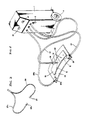
- FIG. 3 is an explanatory view of a conventional spot welder.
- reference numeral 2 designates a rectangular shaped welder body, which is provided at its lower portions with pairs of left and right large and small tires 4 and 6 so that the welder body may be moved according to the work conditions.
- a main switch 8 for turning ON and OFF of a power source for the whole welder ad adjusting knobs 10 and 12 for adjusting welding current values and the like.
- the welder body 2 ist interiorly provided with a welding transformer (not shown) for obtaining a low voltage and a large current, and a secondary side of the welding transformer is provided with a plus terminal (not shown) and a minus terminal (not shown).
- a welding transformer (not shown) for obtaining a low voltage and a large current
- a secondary side of the welding transformer is provided with a plus terminal (not shown) and a minus terminal (not shown).
- a distal end of the welding tip side cable 14 is connected to the plus terminal on the secondary side of the welding transformer, the welding tip side cable being drawn outside from the front side of the welding body 2.
- a tip holder 16 is mounted on the extreme end of the welding tip side cable 14, and a welding tip 18 is mounted on the extreme end of the tip holder 16.
- a distal end of the earth side cable 20 is connected to the minus terminal on the secondary side of the welding transformer, the earth side cable 20 being drawn outside from the front side of the welder body 2.
- a flat earth plate 22 ist mounted on the extreme end of the earth side cable 20 drawn outside from the front side of th welder body 2.
- the earth plate 22 at the extreme end of the earth side cable 20 is placed in close contact with an article to be welded 24 on the lower side by means of a vice or C-clamp (not shown) and they are electrically connected.
- the main switch 8 is turned ON, and the extreme end of the welding tip 18 on the output side is pressed against a predetermined portion of an article to be welded 2 on the upper side.
- the conventional spot welder as described has a problem in that when a portion against which the welding tip 18 is pressed is away from a part with which the earth plate 22 is placed in close contact, the voltage drop increases and the current flowing into the portion against which the welding tip 18 is pressed decreases, sometimes resulting in an incomplete welding.
- An object of the innovation is to provide a spot welder which can apply a good one-side spot welding in a short period of time without producing annealing or deformation in the vicinity of a part to be welded.
- the spot welder comprises a welding transformer for obtaining a low voltage an a large current, and a welding tip side cable and an earth side cable connected to secondary terminals, respectively, of said welding transformer, wherein at least two or more of said earth side cables are provided.
- At least two or more earth side cables are provided. Therefore, if these earth side cables are connected to an article to be welded so that said article to be welded is present therebetween, the voltage drop between the earth side cables and a part to be welded of the article to be welded decreases and the difference of electric resistance caused by the difference in the part to be almost disappears.
- the present innovation has the advantages that since at least two or more earth side cables are provided, even if the part to be welded is changed, variation of the electric resistance between the earth side cable and the part to be welded of the article to be welded can be minimized; the welding time need not be extended; the article to be welded is not denatured or deformed due to generation of heat; and accordingly, good welding can be applied.
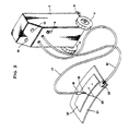
- reference numeral 2 designates a rectangular shaped welder body, which is provided at its lower portions with pairs of left and right large and small tires 4 and 6 so that the welder body may be moved according to the work conditions.
- a main switch 8 for turning ON and OFF a power source for the whole welder and adjusting knobs 10 and 12 for adjusting welding current values and the like.
- the welder body 2 is interiorly provided with a welding transformer (not shown) for obtaining a low voltage and a large current, and a secondary side of the welding transformer is provided with a plus terminal (not shown) and a minus terminal (not shown).
- a distal end of the welding tip side cable 14 is connected to the plus terminal on the secondary side of the welding transformer, the welding tip side cable 14 being drawn outside from the front side of the welding body 2.
- a tip holder 16 is mounted on the extreme end of the welding tip side cable 14, and a welding tip 18 is mounted on the extreme end of the tip holder 16.
- Distal ends of two earth side cables 20 and 20a are connected to the minus terminal (not shown) on the secondary side of the welding transformer, the earth side cables 20 and 20a being drawn outside from the front side of the welder body 2.
- Flat earth plates 22 and 22a are mounted on the extreme ends of the earth side cables 20 and 20a, respectively, drawn outside from the front side of the welder body 2.
- an article to be welded 26 on the upper side is placed on a predetermined position of an article to be welded 24 on the lower side.
- the article to be welded 26 on the upper side is located in an intermediary position of each of the earth plates 22 and 22a.
- the main switch 8 of the welder body 2 is turned ON.
- a current value is set by adjusting knobs 10 and 12, and a timer is set (0.3 to 0.4 second).
- the extreme end of the welding tip 18 is pressed against a predetermined part 28 of the article to be welded 26.
- a large current flows into the part 28 against which the welding tip 18 is pressed concentrically for a predetermined period of time to heat and weld the part 28 of the articles to be welded 24 and 26.
Landscapes
- Engineering & Computer Science (AREA)
- Mechanical Engineering (AREA)
- Resistance Welding (AREA)
Priority Applications (2)
| Application Number | Priority Date | Filing Date | Title |
|---|---|---|---|
| DE69121960T DE69121960T2 (de) | 1990-05-16 | 1991-02-18 | Punktschweissgerät und sein Benutzungsverfahren |
| EP91102251A EP0456967B1 (de) | 1990-05-16 | 1991-02-18 | Punktschweissgerät und sein Benutzungsverfahren |
Applications Claiming Priority (2)
| Application Number | Priority Date | Filing Date | Title |
|---|---|---|---|
| JP51140/90U | 1990-05-16 | ||
| JP5114090 | 1990-05-16 |
Publications (2)
| Publication Number | Publication Date |
|---|---|
| EP0456880A2 true EP0456880A2 (de) | 1991-11-21 |
| EP0456880A3 EP0456880A3 (en) | 1992-06-17 |
Family
ID=12878517
Family Applications (1)
| Application Number | Title | Priority Date | Filing Date |
|---|---|---|---|
| EP19900116540 Withdrawn EP0456880A3 (en) | 1990-05-16 | 1990-08-29 | Spot welder |
Country Status (3)
| Country | Link |
|---|---|
| EP (1) | EP0456880A3 (de) |
| JP (1) | JPH07106463B2 (de) |
| DE (1) | DE69121960T2 (de) |
Families Citing this family (1)
| Publication number | Priority date | Publication date | Assignee | Title |
|---|---|---|---|---|
| JP5554197B2 (ja) * | 2010-09-29 | 2014-07-23 | 本田技研工業株式会社 | スポット溶接方法及びその装置 |
Family Cites Families (7)
| Publication number | Priority date | Publication date | Assignee | Title |
|---|---|---|---|---|
| GB1047334A (de) * | 1900-01-01 | |||
| JPS5240189Y2 (de) * | 1973-02-26 | 1977-09-10 | ||
| JPS5742622Y2 (de) * | 1976-07-03 | 1982-09-20 | ||
| JPS59147783A (ja) * | 1983-02-14 | 1984-08-24 | Hitachi Ltd | 溶接装置の漏電流防止方法 |
| JPS6071486U (ja) * | 1983-10-19 | 1985-05-20 | 本田技研工業株式会社 | マルチスポツト溶接機 |
| JPS6281276A (ja) * | 1985-10-04 | 1987-04-14 | Nissan Motor Co Ltd | スポツト溶接ガン |
| JPS6427782A (en) * | 1987-07-20 | 1989-01-30 | Mazda Motor | Manufacture of car body panel |
-
1990
- 1990-08-29 EP EP19900116540 patent/EP0456880A3/en not_active Withdrawn
- 1990-10-23 JP JP2285482A patent/JPH07106463B2/ja not_active Expired - Lifetime
-
1991
- 1991-02-18 DE DE69121960T patent/DE69121960T2/de not_active Expired - Fee Related
Also Published As
| Publication number | Publication date |
|---|---|
| EP0456880A3 (en) | 1992-06-17 |
| DE69121960T2 (de) | 1997-03-13 |
| JPH0475785A (ja) | 1992-03-10 |
| DE69121960D1 (de) | 1996-10-17 |
| JPH07106463B2 (ja) | 1995-11-15 |
Similar Documents
| Publication | Publication Date | Title |
|---|---|---|
| US4861965A (en) | Method and apparatus for TIG welding | |
| CA2326958A1 (en) | Arc welder and torch for same | |
| CA2192891C (en) | Plasma cutting or arc welding power supply with phase staggered secondary switchers | |
| EG22208A (en) | Fuel cell operated welder | |
| EP0535343B1 (de) | Verfahren und Vorrichtung zum Punktschweissen | |
| EP0456880A2 (de) | Punktschweissgerät | |
| WO2013101870A1 (en) | Welding clamp for controlling current flow through the latter, welding system with such clamp, and method of manufacturing such clamp | |
| JPS63235081A (ja) | スポツト溶接機 | |
| JP4558227B2 (ja) | 溶接電源装置 | |
| US2221646A (en) | Soldering device | |
| US5120924A (en) | Welding method for coated metal articles | |
| ES8700106A1 (es) | Perfeccionamientos en los sistemas de control de los apara- tos de soldadura por resistencia electrica | |
| KR20090048694A (ko) | 휴대용 와이어 타입 열전대 부착장치 | |
| US3702387A (en) | Electrical connections | |
| EP0456967A2 (de) | Punktschweissgerät und sein Benutzungsverfahren | |
| JPH0394977A (ja) | パルスアーク溶接方法及びこの方法を用いたパルスアーク溶接装置 | |
| JPH04503481A (ja) | スタッド溶接装置 | |
| JP2793016B6 (ja) | 加熱器具のヒーター切換装置 | |
| JP3462304B2 (ja) | 電気溶接装置及び電気溶接方法 | |
| US20230302566A1 (en) | Spot welding method and spot welding device | |
| US394892A (en) | Portable electric-welding apparatus | |
| JPS57165178A (en) | Arc welding device | |
| US1216466A (en) | Assembling-machine. | |
| CN2142767Y (zh) | 锡焊机 | |
| CN2173134Y (zh) | 多功能焊机 |
Legal Events
| Date | Code | Title | Description |
|---|---|---|---|
| PUAI | Public reference made under article 153(3) epc to a published international application that has entered the european phase |
Free format text: ORIGINAL CODE: 0009012 |
|
| AK | Designated contracting states |
Kind code of ref document: A2 Designated state(s): DE FR GB IT |
|
| PUAL | Search report despatched |
Free format text: ORIGINAL CODE: 0009013 |
|
| AK | Designated contracting states |
Kind code of ref document: A3 Designated state(s): DE FR GB IT |
|
| STAA | Information on the status of an ep patent application or granted ep patent |
Free format text: STATUS: THE APPLICATION IS DEEMED TO BE WITHDRAWN |
|
| 18D | Application deemed to be withdrawn |
Effective date: 19920901 |