EP0456601B1 - Vorrichtung zur Steuerung einer numerisch inkrementelen Achse in einem Werkzeugmaschinenzentrum - Google Patents
Vorrichtung zur Steuerung einer numerisch inkrementelen Achse in einem Werkzeugmaschinenzentrum Download PDFInfo
- Publication number
- EP0456601B1 EP0456601B1 EP91810287A EP91810287A EP0456601B1 EP 0456601 B1 EP0456601 B1 EP 0456601B1 EP 91810287 A EP91810287 A EP 91810287A EP 91810287 A EP91810287 A EP 91810287A EP 0456601 B1 EP0456601 B1 EP 0456601B1
- Authority
- EP
- European Patent Office
- Prior art keywords
- mobile assembly
- path
- movement
- action
- drive means
- Prior art date
- Legal status (The legal status is an assumption and is not a legal conclusion. Google has not performed a legal analysis and makes no representation as to the accuracy of the status listed.)
- Expired - Lifetime
Links
Images
Classifications
-
- G—PHYSICS
- G05—CONTROLLING; REGULATING
- G05B—CONTROL OR REGULATING SYSTEMS IN GENERAL; FUNCTIONAL ELEMENTS OF SUCH SYSTEMS; MONITORING OR TESTING ARRANGEMENTS FOR SUCH SYSTEMS OR ELEMENTS
- G05B19/00—Program-control systems
- G05B19/02—Program-control systems electric
- G05B19/18—Numerical control [NC], i.e. automatically operating machines, in particular machine tools, e.g. in a manufacturing environment, so as to execute positioning, movement or co-ordinated operations by means of program data in numerical form
- G05B19/19—Numerical control [NC], i.e. automatically operating machines, in particular machine tools, e.g. in a manufacturing environment, so as to execute positioning, movement or co-ordinated operations by means of program data in numerical form characterised by positioning or contouring control systems, e.g. to control position from one programmed point to another or to control movement along a programmed continuous path
- G05B19/21—Numerical control [NC], i.e. automatically operating machines, in particular machine tools, e.g. in a manufacturing environment, so as to execute positioning, movement or co-ordinated operations by means of program data in numerical form characterised by positioning or contouring control systems, e.g. to control position from one programmed point to another or to control movement along a programmed continuous path using an incremental digital measuring device
- G05B19/23—Numerical control [NC], i.e. automatically operating machines, in particular machine tools, e.g. in a manufacturing environment, so as to execute positioning, movement or co-ordinated operations by means of program data in numerical form characterised by positioning or contouring control systems, e.g. to control position from one programmed point to another or to control movement along a programmed continuous path using an incremental digital measuring device for point-to-point control
- G05B19/231—Numerical control [NC], i.e. automatically operating machines, in particular machine tools, e.g. in a manufacturing environment, so as to execute positioning, movement or co-ordinated operations by means of program data in numerical form characterised by positioning or contouring control systems, e.g. to control position from one programmed point to another or to control movement along a programmed continuous path using an incremental digital measuring device for point-to-point control the positional error is used to control continuously the servomotor according to its magnitude
-
- G—PHYSICS
- G05—CONTROLLING; REGULATING
- G05B—CONTROL OR REGULATING SYSTEMS IN GENERAL; FUNCTIONAL ELEMENTS OF SUCH SYSTEMS; MONITORING OR TESTING ARRANGEMENTS FOR SUCH SYSTEMS OR ELEMENTS
- G05B19/00—Program-control systems
- G05B19/02—Program-control systems electric
- G05B19/18—Numerical control [NC], i.e. automatically operating machines, in particular machine tools, e.g. in a manufacturing environment, so as to execute positioning, movement or co-ordinated operations by means of program data in numerical form
- G05B19/401—Numerical control [NC], i.e. automatically operating machines, in particular machine tools, e.g. in a manufacturing environment, so as to execute positioning, movement or co-ordinated operations by means of program data in numerical form characterised by control arrangements for measuring, e.g. calibration and initialisation, measuring workpiece for machining purposes
- G05B19/4015—Numerical control [NC], i.e. automatically operating machines, in particular machine tools, e.g. in a manufacturing environment, so as to execute positioning, movement or co-ordinated operations by means of program data in numerical form characterised by control arrangements for measuring, e.g. calibration and initialisation, measuring workpiece for machining purposes going to a reference at the beginning of machine cycle, e.g. for calibration
Definitions
- the present invention relates to a control device for an incremental digital axis in a machining center.
- the numerical control devices of machining centers generally include in their program a reference point sequence which takes place when the machine is started. This sequence consists in bringing, for each axis, the carriage subjected to the impulse of this axis in a reference position from which the movements to be made during the work sequence will be counted.
- the reference position is determined on a fixed measuring device.
- the position of the moving assembly is constantly detected, both during the reference travel sequence and during the work sequences with respect to this member.
- Fixed rules carrying detection marks generally form said measuring members. They are fixed along the course of the moving parts and include several staggered reference marks, in order to allow adaptation to the particular conditions of each machine. It is therefore necessary, at the time of commissioning, to "activate" that of the reference marks that one wishes to use.
- a sensor has been used for this purpose, generally a contact switch which is placed in the vicinity of the reference mark which it is desired to activate.
- the moving part is moved until the switch is actuated.
- the reference detector is activated and, when it detects the next reference mark reference, the moving part is directed to this reference and the zero position is stored in the control device.
- patent US-3 828 318 which relates to a machine tool with which is associated a digital control system, is described (in particular in the passage between col. 5, line 57 and col. 6, line 27 ) a reference point operation on two axes X and Y for a milling operation.
- the members for measuring the real positions of the moving parts are generally high-precision racks, in which a pinion which drives a rotary encoder, or optical devices mounted on the moving part, capable of reading marks carried on the ruler .
- These tracking devices are adaptable to linear axes as well as to rotary axes.
- US Pat. No. 4,757,458 describes a known device which is applied to a rotary axis. A difference, variable with the number of turns, between the angular position given by a switch and an angular reference, gives the number of turns performed.
- the present invention aims to achieve the improvement in reliability mentioned above, with a reduction in costs, by eliminating the switch or switches necessary so far.
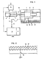
- a carriage 1 Take, for example, the movement of a carriage 1 on a slide 2 in any machining center.
- a tool holder 3 On the carriage 1 is mounted a tool holder 3 which it is not necessary to specify in more detail.
- the carriage 1 is actuated by a jack 4 whose piston 5 is connected to the carriage by a rod 6 and the cylinder 7 of which is supplied with pressurized oil from a system of valves 8, which also need not be described in detail.
- the valve 8 is controlled from a control block 9.
- a part P of block 9 symbolizes a stored program and it can be seen that block 9 is connected by a connection 10 to a signal converter 11 .
- the signal converter 11 is connected, in a manner known per se, to a sensor 12 which moves with the carriage over a series of marks 13, marked on a rule 14 associated with the slide 2.
- the marks 13 allow to determine, in block 9, the instantaneous position of the mobile assembly 1 as well as its speed and the direction of its movement, as will be seen below.
- the rule 14 also carries a series of marks 15 which constitute references.
- the marks 13 and 15 can be of any known type. They are designed according to the type of encoder and sensor used.
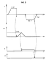
- Fig. 2 shows the mark 15 which has been chosen or, more precisely, the signal emitted by the sensor 12 when the carriage 1 is opposite this mark.
- the signals 16 and 17 made up of series of square pulses, of the same frequency and of the same width, represent the signals emitted by the encoder 11 during the movement of the carriage 1 along the rule 14.
- the phase shift ⁇ by 90 ° between the corresponding signals of the series of signals 16 and of the series of signals 17 makes it possible to determine the direction of movement, while the calculation of the number of signals emitted by the time unit makes it possible to determine the relative position and the speed.
- the third line represents, as a function of time and in synchronism with the first two lines, an activation signal E of the reference point function, therefore activation of the corresponding function in the detector 12.
- the fourth line it represents the emission of the reference signal R when the carriage passes over the reference 15 which has been activated.
- the device is in an initial position which corresponds for example to that of FIG. 1.
- the cylinder 4 is actuated so that the piston moves from right to left.
- the speed of the carriage 1 increases to a first limit value Vref1 and the movement of the carriage thus continues until the moment when its slide comes into contact with a stop 18 which limits its travel.
- Vref1 the speed of the carriage 1 increases to a first limit value
- a displacement stops and the position deviation ⁇ P which, until then, had a very low value corresponding to the determination of the displacement speed as a function of the program, takes an increasing value, the difference between the theoretical position and the actual position increasing in proportion to time.
- the program P controls, on the one hand, the reversal of the direction of movement of the piston 5 in the jack 4 and, on the other hand, the activation of the reference travel function, as indicated above.
- the speed curve of the carriage therefore has the appearance shown in the first line of FIG. 3 and, after a certain delay, increases rapidly to reach a limit value Vref2.
- the carriage 1 therefore moves from left to right with the speed Vref2 until the moment when, the detector 12 being activated, it records the passage signal on that of the markers 15 which has been preselected.
- the displacement starting from the stop it will be the first reference signal 15 or the second, or the third, etc. which will be recorded as zero reference, so that only this reference signal will be functional.
- the position of the rule 14 could be adjusted relative to that of the stop 18 so that the position of the carriage corresponding to the stop A (fig. 3) directly constitutes the reference position. For this it is necessary that the stop position, determined by the stop, be sufficiently precise.
- stop 18 is a member located at the end of the slide. Any element capable of causing, during the movement of the carriage 1, a position deviation reaching a predetermined critical value, can be used to achieve reference travel. The main thing is that it is no longer necessary to electrically connect a detection element to the electronic circuit of the control unit, as was the case until now.
Landscapes
- Engineering & Computer Science (AREA)
- Human Computer Interaction (AREA)
- Manufacturing & Machinery (AREA)
- Physics & Mathematics (AREA)
- General Physics & Mathematics (AREA)
- Automation & Control Theory (AREA)
- Control Of Position Or Direction (AREA)
- Numerical Control (AREA)
Claims (7)
- Vorrichtung zur Steuerung einer numerisch inkrementalen Achse in einem Bearbeitungszentrum, mit einem beweglichen Organ (1), das mit der Achse verbunden ist und zum Zurücklegen einer bestimmten Bahn längs einem Führungsweg (2) vorgesehen ist, mit Antriebsmitteln (4), um das Organ längs dem Weg in der einen und anderen Richtung zu verschieben, mit Steuermitteln (8, 9, 11), die zum Steuern der Antriebsmittel vorgesehen sind, um programmierte Verschiebungen des beweglichen Organes auf dem Führungsweg zu verwirklichen, mit mindestens einer Referenz (15), die an einer vorbestimmten Stelle längs des Weges angeordnet ist und mit Aktivierungsmitteln, die die Referenz im Verlaufe einer Zielverschiebung, die durch das Organ ausgeführt wird, aktivieren,dadurch gekennzeichnet, dass die Steuermittel (8, 9, 11) Mittel (11, 12, 13) zum Detektieren von tatsächlichen Stellungen des beweglichen Organes (1) umfassen und Mittel (9) zum Senden eines Abweichungssignales (ΔP) aufweisen, das aus einem Vergleich zwischen den tatsächlichen Stellungen und den programmierten Stellungen des mobilen Organes stammt,und dass die Aktivierungsmittel zum einen Teil aus einem lokalen Betätigungsmittel (18) bestehen, welches auf dem Weg an einem bestimmten Ort angeordnet ist und dazu vorgesehen ist, eine Abweichung zwischen den wirklichen und programmierten Stellungen des mobilen Organes zu erzeugen, wenn sich das letztere in der Aktionszone des Mittels (18) befindet,und zum anderen Teil Mittel zum Verarbeiten (9) des Abweichungssignales (ΔP) aufweisen, welche, sobald das letztere einem vorbestimmten kritischen Wert (Δ Pref) entspricht, eine Zielverschiebung einleiten.
- Vorrichtung nach Anspruch 1, dadurch gekennzeichnet, dass das Betätigungsmittel (18) einen Anschlag umfasst, welcher zum Blockieren der Verschiebung des beweglichen Organes unter der Wirkung seiner Antriebsmittel in einem vorbestimmten Bereich der Bahn vorgesehen ist.
- Vorrichtung nach Anspruch 1, dadurch gekennzeichnet, dass die Betätigungsmittel ein Bremsmittel umfassen, das zum Bremsen in einem vorbestimmten Bereich auf der Bahn der unter der Wirkung des Antriebsmittels hervorgerufenen Verschiebebewegung des mobilen Organes vorgesehen ist.
- Vorrichtung nach Anspruch 1 mit einer Folge von Referenzen (15), die einem festen Messorgan (14), welches längs des Weges (2) angeordnet ist, zugeordnet sind, dadurch gekennzeichnet, dass die Verarbeitungsmittel derart aufgebaut sind, dass eine aus der Serie vorausgewählte Referenz aktiviert wird, sobald die Zielverschiebung ausgelöst ist.
- Vorrichtung nach Anspruch 4, dadurch gekennzeichnet, dass die Betätigungsmittel (18) aus einem Anschlag bestehen, der dazu vorgesehen ist, die unter der Wirkung der Antriebsmittel hervorgerufene Verschiebebewegung des mobilen Organes in einem vorbestimmten Bereich dessen Weges zu blockieren und dass die Verarbeitungsmittel derart gebildet sind, dass der Anschlag physisch die Referenzposition darstellt.
- Vorrichtung nach Anspruch 1, dadurch gekennzeichnet, dass die Antriebsmittel hydraulische Mittel sind und dass das mobile Organ ein Schnittwerkzeug trägt.
- Vorrichtung nach Anspruch 1, dadurch gekennzeichnet, dass die Antriebsmittel einen Elektromotor umfassen und dass das mobile Organ ein Schnittwerkzeug trägt.
Applications Claiming Priority (2)
| Application Number | Priority Date | Filing Date | Title |
|---|---|---|---|
| CH1384/90 | 1990-04-24 | ||
| CH138490 | 1990-04-24 |
Publications (2)
| Publication Number | Publication Date |
|---|---|
| EP0456601A1 EP0456601A1 (de) | 1991-11-13 |
| EP0456601B1 true EP0456601B1 (de) | 1996-03-27 |
Family
ID=4209167
Family Applications (1)
| Application Number | Title | Priority Date | Filing Date |
|---|---|---|---|
| EP91810287A Expired - Lifetime EP0456601B1 (de) | 1990-04-24 | 1991-04-17 | Vorrichtung zur Steuerung einer numerisch inkrementelen Achse in einem Werkzeugmaschinenzentrum |
Country Status (5)
| Country | Link |
|---|---|
| US (1) | US5283751A (de) |
| EP (1) | EP0456601B1 (de) |
| JP (1) | JPH0749706A (de) |
| DE (1) | DE69118238T2 (de) |
| SG (1) | SG45447A1 (de) |
Families Citing this family (5)
| Publication number | Priority date | Publication date | Assignee | Title |
|---|---|---|---|---|
| JP2833401B2 (ja) * | 1993-03-23 | 1998-12-09 | 三菱電機株式会社 | 駆動制御装置 |
| US5676030A (en) | 1995-08-14 | 1997-10-14 | Crudgington Machine Tools, Inc. | Multi-spindle CNC lathe |
| EP0936446A1 (de) * | 1998-02-10 | 1999-08-18 | Primax Electronics Ltd | System zur Lageveränderungsmessung |
| DE10235982B3 (de) * | 2002-08-06 | 2004-01-22 | Weiler Werkzeugmaschinen Gmbh | Antrieb für linear bewegbare Bauteile einer Werkzeugmaschine |
| CN104723172B (zh) * | 2015-03-25 | 2017-07-21 | 山东钢铁股份有限公司 | 一种钢板定尺机及其定尺方法 |
Family Cites Families (12)
| Publication number | Priority date | Publication date | Assignee | Title |
|---|---|---|---|---|
| US3828318A (en) * | 1972-04-12 | 1974-08-06 | Cam Ind Inc | Operator programmed numerical control system |
| JPS5411622A (en) * | 1977-06-27 | 1979-01-27 | Ricoh Co Ltd | Control method for accurate feed |
| JPS55124632A (en) * | 1979-03-22 | 1980-09-25 | Toshiba Mach Co Ltd | Control system for opening and closing of moving mold for injection molding machine |
| DE3220628A1 (de) * | 1981-06-17 | 1983-01-05 | Renishaw Electrical Ltd., Wotton-Under-Edge, Gloucestershire | Numerisch gesteuerte werkzeugmaschine |
| JPS60230204A (ja) * | 1984-04-27 | 1985-11-15 | Toyoda Mach Works Ltd | 可動体移動制御装置における保安装置 |
| DE3426548A1 (de) * | 1984-07-19 | 1986-01-30 | Burkhardt & Weber GmbH & Co KG, 7410 Reutlingen | Werkzeugmaschine mit einer durch einen rechner unterstuetzten steuerung sowie werkzeugaufnahme und messeinheit fuer eine werkzeugmaschine |
| JPS61143803A (ja) * | 1984-12-17 | 1986-07-01 | Toshiba Corp | ロボツトの制御装置 |
| JPH0778682B2 (ja) * | 1985-08-07 | 1995-08-23 | 株式会社日立製作所 | ロボツトの制御方式 |
| JPS62103703A (ja) * | 1985-10-31 | 1987-05-14 | Yaskawa Electric Mfg Co Ltd | 位置決め制御装置の原点復帰方式 |
| JPS62239204A (ja) * | 1986-04-10 | 1987-10-20 | Shinko Electric Co Ltd | ロボツトの原点位置決め方法 |
| DE3742573C1 (en) * | 1987-12-16 | 1989-03-16 | Gildemeister Ag | Method for correcting the position of a single- or multiple-cut tool |
| DE3743717A1 (de) * | 1987-12-23 | 1989-07-06 | Alfred Dipl Ing Spitzley | Optoelektronische messvorrichtung zur automatischen vermessung der werkzeugschneidkantenlage mit handelsueblichen werkzeugvoreinstellgeraeten |
-
1991
- 1991-04-16 US US07/685,728 patent/US5283751A/en not_active Expired - Fee Related
- 1991-04-17 DE DE69118238T patent/DE69118238T2/de not_active Expired - Fee Related
- 1991-04-17 SG SG1996008907A patent/SG45447A1/en unknown
- 1991-04-17 EP EP91810287A patent/EP0456601B1/de not_active Expired - Lifetime
- 1991-04-23 JP JP3119223A patent/JPH0749706A/ja active Pending
Also Published As
| Publication number | Publication date |
|---|---|
| DE69118238T2 (de) | 1996-10-02 |
| US5283751A (en) | 1994-02-01 |
| EP0456601A1 (de) | 1991-11-13 |
| SG45447A1 (en) | 1998-01-16 |
| JPH0749706A (ja) | 1995-02-21 |
| DE69118238D1 (de) | 1996-05-02 |
Similar Documents
| Publication | Publication Date | Title |
|---|---|---|
| EP0512956B1 (de) | Numerisch gesteuerte Schleifmaschine | |
| EP0456601B1 (de) | Vorrichtung zur Steuerung einer numerisch inkrementelen Achse in einem Werkzeugmaschinenzentrum | |
| EP0141717B1 (de) | Positioniereinrichtung für Roboter | |
| FR2479453A1 (fr) | Dispositif detecteur | |
| FR2583329A1 (fr) | Detecteur acoustique de bris et d'effleurements d'outil et procede d'optimisation de ce detecteur | |
| FR2710406A1 (fr) | Transmetteur d'angle de rotation. | |
| FR2653507A1 (fr) | Dispositif d'accouplement synchrone d'elements tournants d'une machine, notamment une machine d'impression. | |
| EP0309845B1 (de) | Anlage zur Zielverfolgung | |
| CH629411A5 (fr) | Machine a usiner par etincelage erosif. | |
| FR2484887A1 (fr) | Appareil de positionnement repere permettant de faire tourner a ses reperes une table rotative | |
| FR2504838A1 (fr) | Procede de positionnement lateral d'un organe par rapport a un joint forme entre deux surfaces metalliques et presentant des discontinuites | |
| FR2484890A1 (fr) | Machine a meuler equipee d'un dispositif de detection de l'arrivee d'une meule a sa limite d'usure | |
| FR2564016A1 (fr) | Procede de recalage de la trajectoire d'un organe et dispositif pour la mise en oeuvre de ce procede | |
| EP0474603A1 (de) | Verfahren und Gerät zum Steuern einer oder mehrerer Achsen einer Werkzeugmaschine | |
| FR3028942A1 (fr) | Capteur inductif de mesure de la position d'un arbre d'un vehicule | |
| CH639191A5 (fr) | Dispositif pour definir une position de reference d'une piece mobile en translation. | |
| EP1559505B1 (de) | Verfahren zum Kalkulieren einer Positionierabweichung eines Werkzeugs zwischen einer Soll- und einer Ist-Position des Werkzeugs | |
| EP0600783B1 (de) | Verfahren und Vorrichtung zum Positionieren von Stangen in einer Drehmaschine | |
| EP2325710A1 (de) | Verfahren und System zum Ausgleichen der Abmessungsunterschiede in einer Werkzeugmaschine | |
| EP1846727B1 (de) | Optische sonde und diese verwendende einrichtung und methode | |
| FR3015706A1 (fr) | Reperage du centre outil et de l'orientation d'une sonde acoustique dans un repere de reference, par methode ultrasonore | |
| FR2684470A1 (fr) | Organe de commande manuelle a distance. | |
| EP0104113B1 (de) | Verfahren und Vorrichtung zur seitlichen Lageeinstellung eines Organes bezüglich einer zwischen zwei Metalloberflächen gebildeten und Unterbrechungen aufweisenden Spalte | |
| FR2479451A1 (fr) | Dispositif d'affichage pour la mesure de la distance parcourue par des vehicules automobiles | |
| EP0036374A1 (de) | Verfahren und Vorrichtung zum Schweissen mit automatischem Folgen der Schweissnaht |
Legal Events
| Date | Code | Title | Description |
|---|---|---|---|
| PUAI | Public reference made under article 153(3) epc to a published international application that has entered the european phase |
Free format text: ORIGINAL CODE: 0009012 |
|
| AK | Designated contracting states |
Kind code of ref document: A1 Designated state(s): CH DE FR GB IT LI |
|
| 17P | Request for examination filed |
Effective date: 19920425 |
|
| 17Q | First examination report despatched |
Effective date: 19940620 |
|
| GRAH | Despatch of communication of intention to grant a patent |
Free format text: ORIGINAL CODE: EPIDOS IGRA |
|
| GRAA | (expected) grant |
Free format text: ORIGINAL CODE: 0009210 |
|
| AK | Designated contracting states |
Kind code of ref document: B1 Designated state(s): CH DE FR GB IT LI |
|
| REG | Reference to a national code |
Ref country code: CH Ref legal event code: NV Representative=s name: BOVARD AG PATENTANWAELTE |
|
| REF | Corresponds to: |
Ref document number: 69118238 Country of ref document: DE Date of ref document: 19960502 |
|
| ITF | It: translation for a ep patent filed | ||
| GBT | Gb: translation of ep patent filed (gb section 77(6)(a)/1977) |
Effective date: 19960613 |
|
| PLBE | No opposition filed within time limit |
Free format text: ORIGINAL CODE: 0009261 |
|
| PGFP | Annual fee paid to national office [announced via postgrant information from national office to epo] |
Ref country code: FR Payment date: 19970307 Year of fee payment: 7 |
|
| 26N | No opposition filed | ||
| PGFP | Annual fee paid to national office [announced via postgrant information from national office to epo] |
Ref country code: GB Payment date: 19970319 Year of fee payment: 7 |
|
| PGFP | Annual fee paid to national office [announced via postgrant information from national office to epo] |
Ref country code: DE Payment date: 19970321 Year of fee payment: 7 |
|
| PGFP | Annual fee paid to national office [announced via postgrant information from national office to epo] |
Ref country code: CH Payment date: 19970409 Year of fee payment: 7 |
|
| PG25 | Lapsed in a contracting state [announced via postgrant information from national office to epo] |
Ref country code: GB Free format text: LAPSE BECAUSE OF NON-PAYMENT OF DUE FEES Effective date: 19980417 |
|
| PG25 | Lapsed in a contracting state [announced via postgrant information from national office to epo] |
Ref country code: LI Free format text: LAPSE BECAUSE OF NON-PAYMENT OF DUE FEES Effective date: 19980430 Ref country code: FR Free format text: THE PATENT HAS BEEN ANNULLED BY A DECISION OF A NATIONAL AUTHORITY Effective date: 19980430 Ref country code: CH Free format text: LAPSE BECAUSE OF NON-PAYMENT OF DUE FEES Effective date: 19980430 |
|
| GBPC | Gb: european patent ceased through non-payment of renewal fee |
Effective date: 19980417 |
|
| REG | Reference to a national code |
Ref country code: CH Ref legal event code: PL |
|
| PG25 | Lapsed in a contracting state [announced via postgrant information from national office to epo] |
Ref country code: DE Free format text: LAPSE BECAUSE OF NON-PAYMENT OF DUE FEES Effective date: 19990202 |
|
| REG | Reference to a national code |
Ref country code: FR Ref legal event code: ST |
|
| PG25 | Lapsed in a contracting state [announced via postgrant information from national office to epo] |
Ref country code: IT Free format text: LAPSE BECAUSE OF NON-PAYMENT OF DUE FEES;WARNING: LAPSES OF ITALIAN PATENTS WITH EFFECTIVE DATE BEFORE 2007 MAY HAVE OCCURRED AT ANY TIME BEFORE 2007. THE CORRECT EFFECTIVE DATE MAY BE DIFFERENT FROM THE ONE RECORDED. Effective date: 20050417 |