EP0456587B1 - Isolierendes Gehäuse für Miniatur-Lastschalter mit Vorassemblagemitteln - Google Patents
Isolierendes Gehäuse für Miniatur-Lastschalter mit Vorassemblagemitteln Download PDFInfo
- Publication number
- EP0456587B1 EP0456587B1 EP19910420142 EP91420142A EP0456587B1 EP 0456587 B1 EP0456587 B1 EP 0456587B1 EP 19910420142 EP19910420142 EP 19910420142 EP 91420142 A EP91420142 A EP 91420142A EP 0456587 B1 EP0456587 B1 EP 0456587B1
- Authority
- EP
- European Patent Office
- Prior art keywords
- assembly
- housing
- circuit breaker
- cover
- case
- Prior art date
- Legal status (The legal status is an assumption and is not a legal conclusion. Google has not performed a legal analysis and makes no representation as to the accuracy of the status listed.)
- Expired - Lifetime
Links
- 238000010079 rubber tapping Methods 0.000 claims description 3
- 238000005728 strengthening Methods 0.000 claims 1
- 238000003466 welding Methods 0.000 description 2
- 230000002950 deficient Effects 0.000 description 1
- 230000000694 effects Effects 0.000 description 1
- 238000007689 inspection Methods 0.000 description 1
- 238000009434 installation Methods 0.000 description 1
- 238000004519 manufacturing process Methods 0.000 description 1
- 238000000465 moulding Methods 0.000 description 1
- 230000007935 neutral effect Effects 0.000 description 1
- 230000002787 reinforcement Effects 0.000 description 1
- 230000003014 reinforcing effect Effects 0.000 description 1
Images

Classifications
-
- H—ELECTRICITY
- H01—ELECTRIC ELEMENTS
- H01H—ELECTRIC SWITCHES; RELAYS; SELECTORS; EMERGENCY PROTECTIVE DEVICES
- H01H71/00—Details of the protective switches or relays covered by groups H01H73/00 - H01H83/00
- H01H71/02—Housings; Casings; Bases; Mountings
Definitions
- the invention relates to a miniature circuit breaker with modular insulating housing constituted by the assembly of two molded elements of conjugate shapes, in particular a cover and a casing, delimiting an internal compartment for housing the phase circuit, comprising a system of separable contacts , and a control mechanism controlled by a thermomagnetic trip device having a bimetallic strip and a first adjusting screw accessible through a first opening of the housing and cooperating with the foot of the bimetallic strip to adjust the thermal triggering threshold of said trigger, the cover and the housing being traversed by fixing means allowing a final non-removable assembly of the housing (see for example FR-A-2 513 008).
- the thermal trip threshold is carried out after the final assembly, given the need for predetermined positioning of the bimetallic strip inside the housing.
- the threshold is adjusted by the first adjusting screw, and the correct tripping of the circuit breaker for the displayed threshold is checked on a test bench. In the event of inaccuracy during the trip test, the final assembly of the housing makes any subsequent disassembly impossible for inspection or repair. Defective circuit breakers that do not have the precision required by the quality criteria are then automatically discarded.
- the object of the invention is to authorize the disassembly of a miniature circuit breaker box during factory control.
- the circuit breaker according to the invention is characterized in that the housing is equipped with pre-assembly means intended to ensure a removable temporary assembly of the housing suitable for tripping control before the final assembly by the fixing means.
- the pre-assembly means comprise a second pre-assembly screw placed in the vicinity of the embedding zone of the base of the bimetallic strip.
- the bimetallic strip is then correctly positioned, and the factory trip control can be carried out safely for a predetermined overload test current.
- the second pre-assembly screw is removable, in particular of the self-tapping type, and passes through a second opening made in the cover by cooperating with a blind hole of an aligned reinforcing sleeve belonging to the casing.
- An unlockable snap system can be used in place of the preassembly screw.
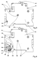
- an insulating housing 10 of a single-pole and neutral differential circuit breaker 12 comprises an intermediate casing 14 associated with two opposite covers 16, 18 to form two adjacent compartments, in particular the circuit breaker compartment 20, and the differential protection compartment 22.
- the circuit breaker compartment 20 contains the phase circuit composed of a system of separable contacts, which is controlled by a lever mechanism 24 and with a thermomagnetic trip device.
- the mechanism can be of the type described in French patent 2,628,262.
- the thermomagnetic trip device comprises a bimetallic strip 26 (FIG. 4) having a deflection movement as a function of the intensity of the current passing through the phase circuit.
- the thermal trigger threshold of the trigger is adjustable by means of a first adjusting screw 28 acting by deformation on the foot 30 of the bimetallic strip 26. The action of the screw 28 on the foot 30 makes it possible to adjust the relative position of the free end of the bimetallic strip 26 relative to the trigger bar.
- the covers 16, 18 are provided with a plurality of orifices 32 for the passage of the fixing means 34 allowing the final assembly of the housing 10 after the mechanism and the phase circuit have been put in place.
- the fixing means can be produced by insulating pins or rods integral with the casing 14, or by rivets crossing the entire width of the housing 10. The arrangement of the insulating rods in the orifices 32 facilitates positioning when the cover 16 is attached to the cover. and housing 14.
- the first screw 28 is accessible by a first opening 35 formed in the narrow lateral face of the housing 10 on the side of the circuit breaker compartment 20.
- the foot 30 of the bimetallic strip 26 is connected, on the one hand, to the contact pad of the terminal. phase (no shown) by a shunt 31, and is carried on the other hand by a support horn 33 ( Figure 4).
- a second pre-assembly screw 36 passes through a second opening 38 of the cover 16 to penetrate into a blind hole of a reinforcement bush 40 coming from molding with the casing 14 (FIG. 2).
- the second pre-assembly screw 36 is arranged in the vicinity of the embedding area of the foot 30 of the bimetallic strip 26, extending orthogonally to the first adjustment screw 28.
- the presence of the second screw 36 makes it possible to carry out the operations of adjusting and controlling the thermal trip threshold in the factory, before final assembly of the housing 10 by the fixing means 14.
- the second screw 36 is advantageously formed by a self-tapping screw , easily removable for possible repair when the test is not satisfactory.
- the provisional assembly of the circuit breaker compartment 20 by the second screw 36 is sufficient to control the thermal tripping threshold, since the tightening effect of the cover 16 against the casing 14 takes place at the foot 30 of the bimetallic strip 26 .
- the final assembly which cannot be dismantled by the fixing means 34 can thus be pushed back at the end of the manufacturing cycle, after the factory setting of the thermal release.
- the second pre-assembly screw 36 remains in place after the final fixing of the elements of the housing 10.
- the final assembly is carried out by riveting or by ultrasonic welding.
- the invention applies to any other type of modular insulating case of miniature circuit breaker with factory control of the correct functioning of the bimetallic strip or of the mechanism, in particular that where the case is formed by the assembly of two conjugate half-shells.
- the second pre-assembly screw 36 is replaced by an unlockable latching system.
Landscapes
- Breakers (AREA)
- Casings For Electric Apparatus (AREA)
- Thermally Actuated Switches (AREA)
Claims (6)
- Kleinleistungsschalter mit modularem Isolierstoffgehäuse (10), das aus zwei geometrisch aufeinander abgestimmten Formstoffleilen, insbesondere einem Deckel (16) und einem Kasten (14) zusammengesetzt ist, die ein inneres Abteil (20) zur Aufnahme des Phasenstromkreises bilden, welcher aus einer trennbaren Kontaktanordnung und einem Schaltmechanismus besteht, der über einen thermomagnetischen Auslöser mit einem Bimetall (26) und einer ersten Einstellschraube (28) angesteuert wird, die über eine im Gehäuse (10) ausgebildete erste Öffnung (35) zugänglich ist und zur Einstellung des thermischen Ansprechwerts des genannten Auslösers mit dem Fußpunkt (30) des Bimetalls (26) zusammenwirkt, wobei der Deckel (16) und der Kasten (14) von Befestigungsmitteln (34) durchquert werden, die einen endgültigen unlösbaren Zusammenbau des Gehäuse (10) ermöglichen, dadurch gekennzeichnet, daß das Gehäuse (10) Vormontagemittel (36) umfaßt, die dazu dienen, einen lösbaren, provisorischen Zusammenbau des Gehäuses (10) zu gewährleisten, der vor dem endgültigen Zusammenbau durch die Befestigungsmittel (34) die Durchführung einer Auslöseprüfung ermöglicht.
- Leistungsschalter nach Anspruch 1, dadurch gekennzeichnet, daß die Vormontagemittel eine zweite Vormontageschraube (36) umfassen, die in der Nähe des Einbauplatzes des Fußpunkts (30) des Bimetalls (26) eingesetzt ist.
- Leistungsschalter nach Anspruch 1 oder 2, dadurch gekennzeichnet, daß die zweite, insbesondere als selbstschneidende Schraube ausgeführte Vormontageschraube (36) entfernt werden kann und eine im Deckel (16) ausgebildete zweite Öffnung (38) durchragt, wobei sie mit einer Blindbohrung einer fluchtend angeordneten, am Kasten (14) angeformten Verstärkungshülse (40) zusammenwirkt.
- Leistungsschalter nach Anspruch 3, dadurch gekennzeichnet, daß die zweite Öffnung (38) und die Hülse (40) zwischen der Aufnahme einer der Anschlußklemmen und dem Boden des Gehäuses (10) angeordnet sind, und daß die erste Einstellschraube (28) rechtwinklig zur zweiten Vormontageschraube (36) sowie zu den Befestigungsmitteln (34) angeordnet ist.
- Leistungsschalter nach irgendeinem der Ansprüche 1 bis 5, dadurch gekennzeichnet, daß die Befestigungsmittel (34) des Gehäuses (10) als Isolierstoffstangen ausgeführt sind, die die zugehörigen Öffnungen (32) des Deckels (16) durchragen, fest mit dem Kasten (14) verbunden sind und beim Zusammenbau des Deckels (16) mit dem Kasten (14) als Positionierstifte dienen, um das Einsetzen der zweiten Vormontageschraube (36) zu erleichtern.
- Leistungsschalter nach Anspruch 1, dadurch gekennzeichnet, daß die Vormontagemittel (36) ein entriegelbares Schnappsystem umfassen, das fest mit dem Deckel (16) und dem Kasten (14) verbunden ist.
Applications Claiming Priority (2)
| Application Number | Priority Date | Filing Date | Title |
|---|---|---|---|
| FR9006552A FR2662018B1 (fr) | 1990-05-10 | 1990-05-10 | Boitier isolant pour un disjoncteur miniature equipe de moyens de preassemblage. |
| FR9006552 | 1990-05-10 |
Publications (2)
| Publication Number | Publication Date |
|---|---|
| EP0456587A1 EP0456587A1 (de) | 1991-11-13 |
| EP0456587B1 true EP0456587B1 (de) | 1995-08-02 |
Family
ID=9396964
Family Applications (1)
| Application Number | Title | Priority Date | Filing Date |
|---|---|---|---|
| EP19910420142 Expired - Lifetime EP0456587B1 (de) | 1990-05-10 | 1991-04-29 | Isolierendes Gehäuse für Miniatur-Lastschalter mit Vorassemblagemitteln |
Country Status (4)
| Country | Link |
|---|---|
| EP (1) | EP0456587B1 (de) |
| DE (1) | DE69111684T2 (de) |
| ES (1) | ES2077829T3 (de) |
| FR (1) | FR2662018B1 (de) |
Families Citing this family (1)
| Publication number | Priority date | Publication date | Assignee | Title |
|---|---|---|---|---|
| FR2718282B1 (fr) | 1994-03-30 | 1996-06-07 | Legrand Sa | Boîtier pour appareil électrique. |
Family Cites Families (6)
| Publication number | Priority date | Publication date | Assignee | Title |
|---|---|---|---|---|
| US3596352A (en) * | 1968-04-16 | 1971-08-03 | Smith Corp A O | Method of calibrating bimetallic elements in a thermal overload switch |
| DE7404983U (de) * | 1974-02-13 | 1975-08-14 | Siemens Ag | Schalterblock, insbesondere Hilfsschalterblock für elektromagnetische Schaltgeräte |
| DE7828060U1 (de) * | 1978-09-21 | 1979-11-29 | Licentia Patent-Verwaltungs-Gmbh, 6000 Frankfurt | Bimetallauslöser |
| DE8126893U1 (de) * | 1981-09-15 | 1982-02-11 | Brown, Boveri & Cie Ag, 6800 Mannheim | Elektrisches Installationsgerät, insbesondere Leitungsschutzschalter |
| US4595896A (en) * | 1984-10-01 | 1986-06-17 | Siemens-Allis, Inc. | Molded case circuit breaker having a reinforced housing |
| IT207990Z2 (it) * | 1986-08-04 | 1988-03-14 | Bassani Spa | Interruttore, preferibilmente manon esclusivamente bipolare ed automatico, destinato al montaggio in telaietti per scatole ad incasso di apparecchiature elettriche di serie civili. |
-
1990
- 1990-05-10 FR FR9006552A patent/FR2662018B1/fr not_active Expired - Fee Related
-
1991
- 1991-04-29 EP EP19910420142 patent/EP0456587B1/de not_active Expired - Lifetime
- 1991-04-29 ES ES91420142T patent/ES2077829T3/es not_active Expired - Lifetime
- 1991-04-29 DE DE1991611684 patent/DE69111684T2/de not_active Expired - Fee Related
Also Published As
| Publication number | Publication date |
|---|---|
| DE69111684D1 (de) | 1995-09-07 |
| EP0456587A1 (de) | 1991-11-13 |
| FR2662018B1 (fr) | 1992-07-24 |
| ES2077829T3 (es) | 1995-12-01 |
| DE69111684T2 (de) | 1996-03-21 |
| FR2662018A1 (fr) | 1991-11-15 |
Similar Documents
| Publication | Publication Date | Title |
|---|---|---|
| EP1126490B1 (de) | Schutzschalter mit in senkrechten Ebenen arbeitendem Schaltschloss und Kniehebelmechanismus | |
| US6144271A (en) | Circuit breaker with easily installed removable trip unit | |
| US5245302A (en) | Automatic miniature circuit breaker with Z-axis assemblable trip mechanism | |
| US5302787A (en) | Automatic miniature circuit breaker with Z-axis assemblable contact assembly | |
| US5250918A (en) | Automatic miniature circuit breaker with Z-axis assemblage current response mechanism | |
| FR2704354A1 (fr) | Mécanisme de commande d'un disjoncteur électrique modulaire. | |
| EP1059654A2 (de) | Thermischer Lastschalter | |
| EP1126492B1 (de) | Schnellauslöser eines Schutzschalters mit einem durch den magnetischen Kreis einer Auslöseelektronik geführten Hauptleiter | |
| ZA200300256B (en) | Ground fault current interrupter/arc fault current interrupter circuit breaker with fail safe mechanism. | |
| US6137386A (en) | Circuit breaker with trip unit mounted tripping plunger and latch therefore | |
| FR2687837A1 (fr) | Composant thermomagnetique de declenchement qui repond au faible courant. | |
| EP0456587A1 (de) | Isolierendes Gehäuse für Miniatur-Lastschalter mit Vorassemblagemitteln | |
| EP0951043B1 (de) | Hilfseinheit mit einer Anzeigevorrichtung zur Auslösung ausgerüstet mit Verschlüsselungsvorrichtung | |
| EP0514230A1 (de) | Stromschaltgerät | |
| FR2994765A1 (fr) | Disjoncteur miniature haute intensite | |
| EP0505292B1 (de) | Phasen- und Nulleiter-Leitungsschutzschalter mit reduziertem Platzbedarf | |
| EP0695459A1 (de) | Betätigungsgriff für schutzschalter | |
| JP3804345B2 (ja) | 回路遮断器 | |
| FR2723469A1 (fr) | Dispositif de declenchement magnetique pour disjoncteur et disjoncteur muni d'un tel dispositif | |
| KR102124796B1 (ko) | 평판형 온도감지 차단기 | |
| FR2553928A1 (fr) | Bilame a chauffage mixte pour declencheur thermique d'un appareil de coupure | |
| JPH0112372Y2 (de) | ||
| JP3793753B2 (ja) | 漏電遮断器 | |
| MXPA95004376A (es) | Conjunto de manija para un disyuntor de circuito | |
| GB2032692A (en) | Circuit breaker anti-rebound and contact kicker means |
Legal Events
| Date | Code | Title | Description |
|---|---|---|---|
| PUAI | Public reference made under article 153(3) epc to a published international application that has entered the european phase |
Free format text: ORIGINAL CODE: 0009012 |
|
| AK | Designated contracting states |
Kind code of ref document: A1 Designated state(s): DE ES GB IT |
|
| 17P | Request for examination filed |
Effective date: 19920513 |
|
| 17Q | First examination report despatched |
Effective date: 19940330 |
|
| RAP1 | Party data changed (applicant data changed or rights of an application transferred) |
Owner name: SCHNEIDER ELECTRIC SA |
|
| GRAA | (expected) grant |
Free format text: ORIGINAL CODE: 0009210 |
|
| AK | Designated contracting states |
Kind code of ref document: B1 Designated state(s): DE ES GB IT |
|
| REF | Corresponds to: |
Ref document number: 69111684 Country of ref document: DE Date of ref document: 19950907 |
|
| ITF | It: translation for a ep patent filed | ||
| REG | Reference to a national code |
Ref country code: ES Ref legal event code: FG2A Ref document number: 2077829 Country of ref document: ES Kind code of ref document: T3 |
|
| GBT | Gb: translation of ep patent filed (gb section 77(6)(a)/1977) |
Effective date: 19951102 |
|
| PLBE | No opposition filed within time limit |
Free format text: ORIGINAL CODE: 0009261 |
|
| STAA | Information on the status of an ep patent application or granted ep patent |
Free format text: STATUS: NO OPPOSITION FILED WITHIN TIME LIMIT |
|
| 26N | No opposition filed | ||
| PGFP | Annual fee paid to national office [announced via postgrant information from national office to epo] |
Ref country code: DE Payment date: 20000417 Year of fee payment: 10 |
|
| PGFP | Annual fee paid to national office [announced via postgrant information from national office to epo] |
Ref country code: ES Payment date: 20000419 Year of fee payment: 10 |
|
| PGFP | Annual fee paid to national office [announced via postgrant information from national office to epo] |
Ref country code: GB Payment date: 20000426 Year of fee payment: 10 |
|
| PG25 | Lapsed in a contracting state [announced via postgrant information from national office to epo] |
Ref country code: GB Free format text: LAPSE BECAUSE OF NON-PAYMENT OF DUE FEES Effective date: 20010429 |
|
| PG25 | Lapsed in a contracting state [announced via postgrant information from national office to epo] |
Ref country code: ES Free format text: LAPSE BECAUSE OF NON-PAYMENT OF DUE FEES Effective date: 20010430 |
|
| GBPC | Gb: european patent ceased through non-payment of renewal fee |
Effective date: 20010429 |
|
| PG25 | Lapsed in a contracting state [announced via postgrant information from national office to epo] |
Ref country code: DE Free format text: LAPSE BECAUSE OF NON-PAYMENT OF DUE FEES Effective date: 20020201 |
|
| REG | Reference to a national code |
Ref country code: ES Ref legal event code: FD2A Effective date: 20030303 |
|
| PG25 | Lapsed in a contracting state [announced via postgrant information from national office to epo] |
Ref country code: IT Free format text: LAPSE BECAUSE OF NON-PAYMENT OF DUE FEES;WARNING: LAPSES OF ITALIAN PATENTS WITH EFFECTIVE DATE BEFORE 2007 MAY HAVE OCCURRED AT ANY TIME BEFORE 2007. THE CORRECT EFFECTIVE DATE MAY BE DIFFERENT FROM THE ONE RECORDED. Effective date: 20050429 |