EP0456007B1 - Device for mounting and adjusting traffic signs or signals and/or illumination means for traffic areas - Google Patents
Device for mounting and adjusting traffic signs or signals and/or illumination means for traffic areas Download PDFInfo
- Publication number
- EP0456007B1 EP0456007B1 EP91105944A EP91105944A EP0456007B1 EP 0456007 B1 EP0456007 B1 EP 0456007B1 EP 91105944 A EP91105944 A EP 91105944A EP 91105944 A EP91105944 A EP 91105944A EP 0456007 B1 EP0456007 B1 EP 0456007B1
- Authority
- EP
- European Patent Office
- Prior art keywords
- traffic
- telescope
- functional part
- base part
- members
- Prior art date
- Legal status (The legal status is an assumption and is not a legal conclusion. Google has not performed a legal analysis and makes no representation as to the accuracy of the status listed.)
- Expired - Lifetime
Links
Images


Classifications
-
- F—MECHANICAL ENGINEERING; LIGHTING; HEATING; WEAPONS; BLASTING
- F21—LIGHTING
- F21V—FUNCTIONAL FEATURES OR DETAILS OF LIGHTING DEVICES OR SYSTEMS THEREOF; STRUCTURAL COMBINATIONS OF LIGHTING DEVICES WITH OTHER ARTICLES, NOT OTHERWISE PROVIDED FOR
- F21V21/00—Supporting, suspending, or attaching arrangements for lighting devices; Hand grips
- F21V21/14—Adjustable mountings
- F21V21/24—Lazy-tongs
-
- B—PERFORMING OPERATIONS; TRANSPORTING
- B60—VEHICLES IN GENERAL
- B60Q—ARRANGEMENT OF SIGNALLING OR LIGHTING DEVICES, THE MOUNTING OR SUPPORTING THEREOF OR CIRCUITS THEREFOR, FOR VEHICLES IN GENERAL
- B60Q7/00—Arrangement or adaptation of portable emergency signal devices on vehicles
-
- E—FIXED CONSTRUCTIONS
- E01—CONSTRUCTION OF ROADS, RAILWAYS, OR BRIDGES
- E01F—ADDITIONAL WORK, SUCH AS EQUIPPING ROADS OR THE CONSTRUCTION OF PLATFORMS, HELICOPTER LANDING STAGES, SIGNS, SNOW FENCES, OR THE LIKE
- E01F9/00—Arrangement of road signs or traffic signals; Arrangements for enforcing caution
- E01F9/60—Upright bodies, e.g. marker posts or bollards; Supports for road signs
- E01F9/623—Upright bodies, e.g. marker posts or bollards; Supports for road signs characterised by form or by structural features, e.g. for enabling displacement or deflection
- E01F9/646—Upright bodies, e.g. marker posts or bollards; Supports for road signs characterised by form or by structural features, e.g. for enabling displacement or deflection extensible, collapsible or pivotable
-
- F—MECHANICAL ENGINEERING; LIGHTING; HEATING; WEAPONS; BLASTING
- F16—ENGINEERING ELEMENTS AND UNITS; GENERAL MEASURES FOR PRODUCING AND MAINTAINING EFFECTIVE FUNCTIONING OF MACHINES OR INSTALLATIONS; THERMAL INSULATION IN GENERAL
- F16M—FRAMES, CASINGS OR BEDS OF ENGINES, MACHINES OR APPARATUS, NOT SPECIFIC TO ENGINES, MACHINES OR APPARATUS PROVIDED FOR ELSEWHERE; STANDS; SUPPORTS
- F16M11/00—Stands or trestles as supports for apparatus or articles placed thereon Stands for scientific apparatus such as gravitational force meters
- F16M11/02—Heads
- F16M11/04—Means for attachment of apparatus; Means allowing adjustment of the apparatus relatively to the stand
- F16M11/043—Allowing translations
- F16M11/046—Allowing translations adapted to upward-downward translation movement
-
- F—MECHANICAL ENGINEERING; LIGHTING; HEATING; WEAPONS; BLASTING
- F16—ENGINEERING ELEMENTS AND UNITS; GENERAL MEASURES FOR PRODUCING AND MAINTAINING EFFECTIVE FUNCTIONING OF MACHINES OR INSTALLATIONS; THERMAL INSULATION IN GENERAL
- F16M—FRAMES, CASINGS OR BEDS OF ENGINES, MACHINES OR APPARATUS, NOT SPECIFIC TO ENGINES, MACHINES OR APPARATUS PROVIDED FOR ELSEWHERE; STANDS; SUPPORTS
- F16M11/00—Stands or trestles as supports for apparatus or articles placed thereon Stands for scientific apparatus such as gravitational force meters
- F16M11/20—Undercarriages with or without wheels
- F16M11/24—Undercarriages with or without wheels changeable in height or length of legs, also for transport only, e.g. by means of tubes screwed into each other
- F16M11/26—Undercarriages with or without wheels changeable in height or length of legs, also for transport only, e.g. by means of tubes screwed into each other by telescoping, with or without folding
- F16M11/28—Undercarriages for supports with one single telescoping pillar
-
- F—MECHANICAL ENGINEERING; LIGHTING; HEATING; WEAPONS; BLASTING
- F16—ENGINEERING ELEMENTS AND UNITS; GENERAL MEASURES FOR PRODUCING AND MAINTAINING EFFECTIVE FUNCTIONING OF MACHINES OR INSTALLATIONS; THERMAL INSULATION IN GENERAL
- F16M—FRAMES, CASINGS OR BEDS OF ENGINES, MACHINES OR APPARATUS, NOT SPECIFIC TO ENGINES, MACHINES OR APPARATUS PROVIDED FOR ELSEWHERE; STANDS; SUPPORTS
- F16M11/00—Stands or trestles as supports for apparatus or articles placed thereon Stands for scientific apparatus such as gravitational force meters
- F16M11/20—Undercarriages with or without wheels
- F16M11/24—Undercarriages with or without wheels changeable in height or length of legs, also for transport only, e.g. by means of tubes screwed into each other
- F16M11/38—Undercarriages with or without wheels changeable in height or length of legs, also for transport only, e.g. by means of tubes screwed into each other by folding, e.g. pivoting or scissors tong mechanisms
-
- F—MECHANICAL ENGINEERING; LIGHTING; HEATING; WEAPONS; BLASTING
- F16—ENGINEERING ELEMENTS AND UNITS; GENERAL MEASURES FOR PRODUCING AND MAINTAINING EFFECTIVE FUNCTIONING OF MACHINES OR INSTALLATIONS; THERMAL INSULATION IN GENERAL
- F16M—FRAMES, CASINGS OR BEDS OF ENGINES, MACHINES OR APPARATUS, NOT SPECIFIC TO ENGINES, MACHINES OR APPARATUS PROVIDED FOR ELSEWHERE; STANDS; SUPPORTS
- F16M13/00—Other supports for positioning apparatus or articles; Means for steadying hand-held apparatus or articles
- F16M13/02—Other supports for positioning apparatus or articles; Means for steadying hand-held apparatus or articles for supporting on, or attaching to, an object, e.g. tree, gate, window-frame, cycle
-
- G—PHYSICS
- G09—EDUCATION; CRYPTOGRAPHY; DISPLAY; ADVERTISING; SEALS
- G09F—DISPLAYING; ADVERTISING; SIGNS; LABELS OR NAME-PLATES; SEALS
- G09F13/00—Illuminated signs; Luminous advertising
- G09F13/02—Signs, boards, or panels, illuminated by artificial light sources positioned in front of the insignia
-
- G—PHYSICS
- G09—EDUCATION; CRYPTOGRAPHY; DISPLAY; ADVERTISING; SEALS
- G09F—DISPLAYING; ADVERTISING; SIGNS; LABELS OR NAME-PLATES; SEALS
- G09F13/00—Illuminated signs; Luminous advertising
- G09F13/04—Signs, boards or panels, illuminated from behind the insignia
- G09F13/0418—Constructional details
- G09F13/0472—Traffic signs
-
- F—MECHANICAL ENGINEERING; LIGHTING; HEATING; WEAPONS; BLASTING
- F16—ENGINEERING ELEMENTS AND UNITS; GENERAL MEASURES FOR PRODUCING AND MAINTAINING EFFECTIVE FUNCTIONING OF MACHINES OR INSTALLATIONS; THERMAL INSULATION IN GENERAL
- F16M—FRAMES, CASINGS OR BEDS OF ENGINES, MACHINES OR APPARATUS, NOT SPECIFIC TO ENGINES, MACHINES OR APPARATUS PROVIDED FOR ELSEWHERE; STANDS; SUPPORTS
- F16M2200/00—Details of stands or supports
- F16M2200/02—Locking means
- F16M2200/025—Locking means for translational movement
- F16M2200/027—Locking means for translational movement by friction
-
- F—MECHANICAL ENGINEERING; LIGHTING; HEATING; WEAPONS; BLASTING
- F16—ENGINEERING ELEMENTS AND UNITS; GENERAL MEASURES FOR PRODUCING AND MAINTAINING EFFECTIVE FUNCTIONING OF MACHINES OR INSTALLATIONS; THERMAL INSULATION IN GENERAL
- F16M—FRAMES, CASINGS OR BEDS OF ENGINES, MACHINES OR APPARATUS, NOT SPECIFIC TO ENGINES, MACHINES OR APPARATUS PROVIDED FOR ELSEWHERE; STANDS; SUPPORTS
- F16M2200/00—Details of stands or supports
- F16M2200/06—Arms
- F16M2200/061—Scissors arms
Definitions
- the invention relates to a device for attaching and aligning traffic facilities, including traffic signs and warning lights, and / or lighting devices on traffic areas, for example for securing traffic at construction or hazard locations, the actual traffic device and / or lighting device as a functional part on one of the Base part to be attached or set up traffic area is worn.
- Traffic devices and lighting devices of this type are known in a wide variety of designs and with a wide variety of information contents, for example as traffic signs, signposts, signposts, traffic control boards, barrier gates, barrier boards, etc.
- traffic signs are usually permanently attached to traffic areas, for example streets. However, they are also required for temporary attachment to construction sites and special danger spots.Lighting and warning devices are known both for the permanently installed traffic facilities and for the temporary traffic facilities that facilitate the detection of the respective traffic facilities in the dark and better attract the attention of road users to direct the respective traffic facilities.
- Warning lights are known as a special group of such traffic and lighting devices, which are used in particular at danger points and construction sites both during the day and at night. Such warning lights are often for short-term and quick use, for example Accident sites etc. known.
- the functional part containing the optical devices and the base part containing the electrical supply devices and switching devices are connected to one another to form a fixed unit of a warning light which is carried in motor vehicles of the police, fire service, technical aid agency, etc. and directly in the event of accidents or special operations removed from the vehicle and used for protection.
- Flash or halogen light is mainly used to improve the warning effect. Because of the limited space in the motor vehicle, such warning lights have to be kept as small and compact as possible. In the event of use, these warning lights are placed on the traffic area, for example on the street, and aligned with the incoming traffic. The mounting height is very low due to the necessary compact design of such warning lights, which means the lack that the first vehicle can only see the light, whereas the next and all other drivers can no longer see the light directly, i.e. the warning effect no longer exists or is insecure.
- warning lights In another known embodiment of the warning lights mentioned above, it is known in particular for use on construction sites to design the functional part and the base part of the warning light as two separate units, the functional part being placed on a shut-off part, for example on a beacon or barrier, and the base part on Foot of the shut-off part is parked. It then only extends from the connecting cable Base part for the functional part of the warning light. Warning lights of this design are only suitable to a limited extent for carrying in police, fire service etc. vehicles and for use on a case-by-case basis in the event of accidents or special operations, because the mounting parts carrying such shut-off parts are too bulky for this.
- the object of the invention is therefore to provide a device for attaching and aligning traffic facilities, including traffic signs and warning lights and / or lighting devices on traffic areas, which on the one hand have a compact design to be carried in emergency vehicles of the police, fire service, etc. and on the other hand the Create the possibility of being able to set up such traffic facilities or lighting facilities quickly and easily without any significant need for personnel and at the same time to install the functional part with the relevant information and warning content continuously in an effective position, for example at a suitable viewing height for the driver of motor vehicles, especially if such vehicles are approaching in a vehicle queue .
- a warning lamp with an upper part for receiving the optics and a lower part for receiving the power supply is known, in which a scissor gear is arranged between the upper and lower part.
- This warning light is transported in the compressed state of the scissor gear, so that its dimensions are not significantly larger than the usual warning lights during transport.
- the upper part with the light source is pulled out with the help of the scissors gear, so that the light source can be positioned in an effective position above the road surface.
- a disadvantage of this known warning light is that the scissor gear does not have sufficient rigidity and, for example, due to wind, the light source can oscillate back and forth.
- the scissors-type transmission can only be locked in this known warning light in the retracted or extended position, or at intermediate, fixed predetermined locking points, so that the upper part can not be continuously adjusted with respect to the lower part.
- EP-A-0 135 756 a hazard warning lamp which has an upper part which is height-adjustable relative to a lower part, the height being adjusted by telescopes which are accommodated in the lower part in the pushed-together state.
- the telescopes are designed such that they are locked in the extended position Condition can be held by a pawl.
- the pawl snaps onto a shoulder of the lower telescope, with one shoulder of the upper telescope reaching under the shoulder of the lower telescope.
- a major disadvantage of this hazard warning light is that a continuous adjustment of the upper part relative to the lower part is also not possible, since due to this configuration the telescopes can only be locked in the retracted or extended position.
- the invention proposes that the movable and changeable connecting device is provided in the manner of a telescopic rod between the base part and the functional part of the traffic device or lighting device.
- friction elements in the form of rings made of rubber-elastic material are inserted in such a way that the telescopic members can be moved axially relative to one another, but are held sufficiently firmly in a mutually set position for the transfer of the load of the functional part, so that the functional part can be selected in Desired position is adjustable relative to the base part, the friction elements between the adjacent telescopic members of the telescopic rod can be rolled.
- the invention provides a particularly advantageous method of assembly for the traffic facilities, including traffic signs and lighting devices, which are permanently or long-term installed on traffic areas.
- the invention offers particular advantage for temporarily used traffic facilities and lighting devices, in particular for warning lights.
- the invention provides a temporary warning light that can be set up at danger spots, construction sites, accident sites, etc. and that can be carried in emergency vehicles without requiring particular space.
- the base part should be designed in the manner of a foot part to be set up on the respective traffic area and that for supplying the any electrical devices or switching devices required in or on the functional part contain necessary.
- Such a unit with the base part designed as a foot part is to be set up at the point of use, while the functional part is brought into a suitable position by means of the movable and changeable connecting device. This work is simple, quick and can be carried out by a single person.
- the functional part can contain optical devices in the form of a light-beaming headlight to be aligned with the incoming traffic, the radiation direction of which can be set or adjusted essentially parallel to the traffic area.
- the functional part is adjustable up to approximately the driver's height and the light beam emanating from it is directed substantially at a constant height along the traffic area, for example a street.
- Such a warning light can thus be reliably recognized along a roadway and through the windows of the vehicles for the drivers of a plurality of vehicles arriving in a queue in a row.
- the telescopic members of the telescopic rod are concentrically fitting pieces of tube, all of which have the same length, such that the telescopic rod can be pushed together to the length of a single telescopic member.
- the telescopic rod is so low when pushed together that the overall height of the previous warning lamp units is not exceeded.
- the other dimensions, such as the length and width of the warning light, are no larger than those of the previous warning light units when the telescopic rod is pushed together.
- the warning light according to the invention in this embodiment fits into the receiving boxes present in emergency vehicles.
- the device according to the invention also offers the possibility of carrying other traffic devices and lighting devices in emergency vehicles, since the shield-shaped traffic signs, beacons, barriers and boards take up little space due to their flat design in vehicles and instead of the previous bulky assembly frames, a plurality of pushed together Telescopic poles can be carried easily.
- Two or more telescopic poles can be used for the installation of barrier barriers and larger barrier panels, which has the advantage that differences in height can also be compensated for when installing on sloping sites, for example road embankments, and horizontal arrangement of barriers etc. can be easily achieved.
- Conventional telescopic rods cannot be used for the assembly of traffic and lighting devices because only through the inventive installation of the locking devices or friction elements between the telescopic members of the telescopic rod have the requirements for the complete merging of the telescopic rod to the size of a single telescopic member been created.
- a particularly simple and surprising possibility for the design of the friction elements has emerged in the context of the invention that the telescopic members of the telescopic rod have a rounded cross-sectional shape and the friction elements are rings with a circular cross-section.
- the ring-shaped friction elements can be more easily rolled off if the ring has regions of greater thickness and regions of smaller thickness on its ring circumference in an essentially uniform spacing distribution.
- the areas of greater thickness can be substantially spherical.
- the telescopic members of the telescopic rod can be pipe sections which have, at one end - preferably the lower - a protruding bead or edge with a groove adjoining the pipe section and at the other end a stepped section with a reduced outer section compared to the pipe section - Have and inner diameter, such that the protruding bead or edge can still slide into the next larger pipe section, but not in its stepped section.
- the two elastic pieces of tube inserted are inserted into the annular groove before the telescopic rod is installed.
- the smaller piece of pipe is then inserted into the next larger piece of pipe and can be pushed through until the elastic ring comes to a stop against the shoulder formed at the beginning of the stepped section.
- the elastic ring emerges from the ring groove and is pressed between the inner surface of the larger pipe piece and the outer surface of the smaller pipe piece during the movement process so that a force is necessary to axially move the pipe pieces against one another.
- This avoids any unwanted mobility between the pipe sections in the telescopic rod, with the result that the telescopic rod automatically stops at any extension height and does not wobble. There is thus an automatic locking of the pipe sections of the telescopic rod in any position.
- the inserted rubber-elastic rings ensure sufficient friction of the pipe pieces against each other in any position of the telescopic rod, not only in the axial but also in the radial direction, so that there is also sufficient protection against rotation against accidental rotary movements.
- the anti-twist protection can be reinforced by choosing a non-circular but at least rounded, for example elliptical, cross-sectional shape instead of a circular cross-section of the pipe sections. It is also conceivable that the individual telescopic members of the telescopic rod have axially extending profiles in the manner of a tongue and groove combination that run into one another.
- the pipe sections can be designed to be slightly expanded just below the end position by increasing the inside diameter.
- the rubber-elastic ring is relieved here. There is no more friction and the pipe pieces practically collapse. Then no more force has to be used. Conversely, when the telescopic rod is pulled apart, force only has to be applied in a more or less long area before the end position.
- the traffic device according to the invention is particularly advantageous for the user when the same optical effect as with a traffic cone is achieved by alternately coloring the telescopic members of the telescopic rod in white and red.
- the warning light fulfills a double function: light + traffic cone.
- movable feet can be provided on the base part to enlarge the footprint. For example, such feet can be pivoted or pulled out in the base region of the base part.
- a omnidirectional emitter instead of a directional emitter with a warning light.
- the warning lamp can therefore be equipped with interchangeable lamp upper parts. This is made possible by the fact that the functional part containing the light source and the optical devices is detachably and / or interchangeably attached to the movable and changeable connecting device.
- a traffic or lighting device in particular a warning light
- a traffic or lighting device for special applications in its compact state, i.e. to be used with the connecting device pushed together between the functional part and the base part.
- the connecting device pushed together between the functional part and the base part.
- a switch can be provided which can be actuated by turning the functional part relative to the base part and / or the connecting device to switch the lamp on and off.
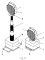
- the warning light shown in Figure 1 for comparison is a conventional design. It has a functional part 1 with a light source not visible here, e.g. a light bulb or a flash tube, which is in the focus of a light-bundling optical device 2.
- the base part 3 which is a power supply device e.g. Contains batteries or accumulators and an electrical or electronic circuit.
- This known warning light according to FIG. 1 is placed on the road as a unit in use and warns only the driver of a first vehicle in oncoming dense traffic, while it is not visible to the drivers of vehicles immediately behind.
- a functional part 1 in the manner of a Headlight light-bundling optical device 2 and a base part 3 are provided.
- a connecting device is attached between the functional part 1 and the base part 3, by means of which the height of the functional part 1 can be adjusted in relation to the set-up base part.
- the direction of radiation of the headlamp can be set in the desired height position in a direction of radiation running essentially parallel to the traffic area.
- the lateral setting of the radiation direction along a street or the like is carried out by correspondingly setting up the warning lamp with its base part designed as a lamp base.
- the movable connecting device contains between the functional part 1 and the base part 3, a length-adjustable carrier for the functional part 1, which is designed in the manner of a telescopic rod 5.
- the base part 3 has extendable feet 6 which increase the stability of the warning light. Instead of the extendable feet 6, pivotable levers could also be provided as additional feet in the corner areas of the housing of the base part 3.
- parts 18 and 19 of a locking device are provided, which can be fixed by rotating the functional part 1 relative to the base part 3 such that the telescopic rod 5 cannot be pulled out.
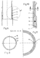
- Figure 3 shows a section through the telescopic rod 5 in a preferred embodiment.
- the telescopic rod 5 is composed of tubular telescopic members 7, 8, 9, 10 of the same length, which have a round cross section can.
- the telescopic members 7, 8, 9, 10 have different diameters such that they can be arranged one inside the other. They are also shaped so that at one end - preferably the lower - a protruding bead 11 or edge with an annular groove 12 adjoining the tube and at the other end a stepped section 13 with a reduced outer and inner diameter compared to the tube is provided.
- the outer diameter of the protruding bead 11 is such that it can still slide in the tube section of the next largest telescopic member.
- a rubber-elastic ring 14 for example made of rubber or plastic, is provided, which is inserted into the annular groove 12 of each telescopic member 7, 8, 9, 10 before the assembly of the telescopic rod 5, after which the respective telescopic member with the next smallest diameter together with the ring 14 is inserted into the next largest telescopic member and pushed through until the ring comes to a stop on the shoulder formed by the section 13.
- the rubber-elastic rings 14 are moved out of their respective annular groove 12 and pressed and rolled between the inner surface of the larger and the outer surface of the respectively smaller tubular telescopic member of the telescopic rod 5 during the movement process. that a force is necessary to move the telescopic members 7, 8, 9, 10 against each other.
- the telescopic rod 5 remains at any extension height and does not tend to wobble its telescopic members 7, 8, 9, 10.
- the telescopic members 7 and 8 of the telescopic rod 5 shown there, for example, are in an intermediate position.
- the rubber-elastic ring 14 is pressed between the two telescopic members 7 and 8 and generates sufficient friction to hold the telescopic members 7 and 8 in a mutual position. Furthermore, the ring 14 forms a seal between the telescopic members 7 and 8.
- the telescopic members 7, 8, 9 and 10 are designed such that the lower bead 11 has changed directly into the tube shape without the formation of an annular groove above the bead 11.
- the ring is 14 even in the upper end position of the telescopic members under full pressure, so that the locking of the telescopic members 7, 8, 9, 10 in their end position should be even more secure.
- the introduction of the respective thinner tubes into the thicker tubes, that is, the assembly of the telescopic rod 5, is more difficult.
- the tubular telescopic members 7, 8, 9, 10 provided in the upper part of their main tubular section with a smaller outer diameter 15.
- the telescopic members 7, 8, 9, 10 can practically coincide when the rubber-elastic ring 14 reaches the area of smaller outside diameter.
- the telescopic rod 5 can be pulled out practically without force, as long as the rubber-elastic ring 14 is located in this area with a reduced outer diameter 15.
- the telescopic rod 5 is then no longer locked over its entire extension length in each extension position.
- FIG. 8 shows a modified embodiment of the rubber-elastic ring 14 used as the friction element.
- the ring 14 has a substantially uniform spacing on its circumference, spherically thickened regions 20 and regions 21 of reduced thickness in between. However, these areas of reduced thickness also have a circular cross section.
- the ring 14 is more easily movable between two adjacent telescopic members 7, 8, 9, 10 of the telescopic rod 5, even at lower temperatures.
- FIGS. 9 to 11 show details of the telescope, wherein axial profiles are provided in the manner of tongue and groove combinations, namely in the form of an axial groove or groove 16 and an axial rib or spring 17. These parts run with axial relative movement of the tubular telescopic members 7, 8, 9, 10 of the telescopic rod 5 into each other and prevent the telescopic members 7, 8, 9, 10 can be rotated against each other.
- a switch that can be actuated in a simplified manner for switching the warning light on and off can be provided, which can be actuated by rotating the functional part 1 relative to the connecting device and / or the base part 3.
- FIGS. 12 to 13 show another possible application of the connecting device between functional part 1 and base part 3 in its embodiment as a telescopic rod 5.
- the functional part 1 of the traffic device is a shut-off bar 22, which can be equipped with a number of optical devices 2 in the manner of warning lights on its upper side.
- the barrier bar 1 is attached to two telescopic rods 5. Each of these telescopic rods 5 sits on a base part 3.
- the power supply devices and switching devices required for the operation of the optical devices 2 can be accommodated in the base parts.
- the construction of the barrier with barrier bars 22 and telescopic rods 5 and base parts 3 offers the advantage that the telescopic rods 5 not only allow a desired height adjustment of the barrier beam 22, but also the compensation of differences in height of the sites caused by the terrain.
- the shut-off bar 22 can thereby be aligned horizontally at any time.
- the example in FIG. 13 is a Traffic board 23, which is set up permanently or temporarily on traffic areas by means of a conventional mounting frame 24.
- a lighting device 25 is arranged above and in front of the traffic board 23 on the mounting frame 24.
- This lighting device 25 is fastened to the mounting frame by means of a telescopic rod 5.
- the mounting frame 24 represents the common base part 3 for the traffic sign 23 and the lighting device 25.
- a further base part can also be provided which carries the telescopic rod 5 and the power supply devices and switching devices required for the lighting device 25 contains.
- the attachment of the lighting device 25 by means of a telescopic rod 5 arranged horizontally in this case offers the advantage that the distance of the lighting device 25 in front of the traffic sign 23 can be adjusted and thus the angle of incidence of the light beams hitting the traffic sign 23. This is of particular importance for traffic signs with a reflective surface.
- the optimal direction of radiation of the light reflected by the traffic sign 23 with respect to the road users moving towards the traffic sign can be set.
- a large number of other possible uses of the movable, changeable connecting device on traffic devices and lighting devices to be used in traffic are possible, in particular in their embodiment as a telescopic rod 5.
Abstract
Description
Die Erfindung betrifft eine Vorrichtung zum Anbringen und Ausrichten von Verkehrseinrichtungen, einschließlich Verkehrszeichen sowie Warnleuchten, und/oder Beleuchtungseinrichtungen an Verkehrsflächen, beispielsweise für die Absicherung des Verkehrs an Bau- oder Gefahrenstellen, wobei die eigentliche Verkehrseinrichtung und/oder Beleuchtungseinrichtung als Funktionsteil auf einem an der Verkehrsfläche anzubringenden bzw. aufzustellenden Basisteil getragen ist.The invention relates to a device for attaching and aligning traffic facilities, including traffic signs and warning lights, and / or lighting devices on traffic areas, for example for securing traffic at construction or hazard locations, the actual traffic device and / or lighting device as a functional part on one of the Base part to be attached or set up traffic area is worn.
Verkehrseinrichtungen und Beleuchtungseinrichtungen solcher Art sind in verschiedensten Ausführungen und mit den verschiedensten Informationsgehalten bekannt, beispielsweise als Verkehrszeichen, Wegweiser, Vorwegweiser, Verkehrslenkungstafeln, Absperrschranken, Absperrtafeln usw.. Solche Verkehrseinrichtungen und Verkehrszeichen sind zumeist ständig an Verkehrsflächen, beispielsweise Straßen angebracht. Sie werden jedoch auch für zeitweilige Anbringung an Baustellen und besonderen Gefahrenstellen benötigt, sowohl bei den ständig angebrachten Verkehrseinrichtungen als auch bei den zeitweilig anzubringenden Verkehrseinrichtungen sind Beleuchtungs- und Warneinrichtungen bekannt, die das Erkennen der jeweiligen Verkehrseinrichtungen bei Dunkelheit erleichtern und die Aufmerksamkeit der Verkehrsteilnehmer besser auf die jeweiligen Verkehrseinrichtungen lenken sollen.Traffic devices and lighting devices of this type are known in a wide variety of designs and with a wide variety of information contents, for example as traffic signs, signposts, signposts, traffic control boards, barrier gates, barrier boards, etc. Such traffic devices and traffic signs are usually permanently attached to traffic areas, for example streets. However, they are also required for temporary attachment to construction sites and special danger spots.Lighting and warning devices are known both for the permanently installed traffic facilities and for the temporary traffic facilities that facilitate the detection of the respective traffic facilities in the dark and better attract the attention of road users to direct the respective traffic facilities.
Als eine besondere Gruppe solcher Verkehrs- und Beleuchtungseinrichtungen sind Warnleuchten bekannt, die insbesondere an Gefahrenstellen und Baustellen sowohl tagsüber als auch nachts eingesetzt werden. Solche Warnleuchten sind vielfach für kurzfristigen und schnellen Einsatz, beispielsweise an Unfallstellen usw. bekannt. So sind bei einer bekannten Ausführung, das die optischen Einrichtungen enthaltende Funktionsteil und das die elektrischen Versorgungseinrichtungen und Schalteinrichtungen enthaltende Basisteil zu einer festen Einheit einer Warnleuchte miteinander verbunden, die in Kraftfahrzeugen der Polizei, Feuerwehr, Technischen Hilfswerk usw. mitgeführt und bei Unfällen oder Sondereinsätzen unmittelbar aus dem Fahrzeug geholt und zur Absicherung eingesetzt wird.Warning lights are known as a special group of such traffic and lighting devices, which are used in particular at danger points and construction sites both during the day and at night. Such warning lights are often for short-term and quick use, for example Accident sites etc. known. Thus, in a known embodiment, the functional part containing the optical devices and the base part containing the electrical supply devices and switching devices are connected to one another to form a fixed unit of a warning light which is carried in motor vehicles of the police, fire service, technical aid agency, etc. and directly in the event of accidents or special operations removed from the vehicle and used for protection.
Zur besseren Warnwirkung kommt vorwiegend Blitzlicht oder Halogenlicht zur Anwendung. Wegen der beschränkten Platzverhältnisse im Kraftfahrzeug müssen solche Warnleuchten möglichst klein und kompakt gehalten werden. Im Einsatzfall werden diese Warnleuchten auf die Verkehrsfläche, beispielsweise auf die Straße gestellt und auf den ankommenden Verkehr ausgerichtet. Die Lichtpunkthöhe ist wegen der notwendigen kompakten Bauweise solcher Warnleuchten sehr niedrig, was den Mangel bedingt, daß allenfalls das erste Fahrzeug die Leuchte wahrnehmen kann, wogegen die nächsten und alle weiteren Fahrzeugführer die Leuchte nicht mehr direkt wahrnehmen können, also die Warnwirkung nicht mehr vorhanden oder unsicher ist.Flash or halogen light is mainly used to improve the warning effect. Because of the limited space in the motor vehicle, such warning lights have to be kept as small and compact as possible. In the event of use, these warning lights are placed on the traffic area, for example on the street, and aligned with the incoming traffic. The mounting height is very low due to the necessary compact design of such warning lights, which means the lack that the first vehicle can only see the light, whereas the next and all other drivers can no longer see the light directly, i.e. the warning effect no longer exists or is insecure.
In einer anderen bekannten Ausführung der oben genannten Warnleuchten ist es insbesondere für den Einsatz an Baustellen bekannt, das Funktionsteil und das Basisteil der Warnleuchte als zwei getrennte Einheiten auszubilden, wobei das Funktionsteil auf einem Absperrungsteil, beispielsweise auf einer Bake oder Absperrschranke aufgesetzt und das Basisteil am Fuß des Absperrungsteiles abgestellt wird. Es erstreckt sich dann lediglich ein Verbindungskabel vom Basisteil zum Funktionsteil der Warnleuchte. Warnleuchten dieser Ausführung eignen sich aber nur bedingt zum Mitführen in Einsatzfahrzeugen der Polizei, Feuerwehr usw. und zum Einsatz von Fall zu Fall bei Unfällen oder Sondereinsätzen, weil die solche Absperrungsteile tragenden Montageteile hierfür zu sperrig sind.In another known embodiment of the warning lights mentioned above, it is known in particular for use on construction sites to design the functional part and the base part of the warning light as two separate units, the functional part being placed on a shut-off part, for example on a beacon or barrier, and the base part on Foot of the shut-off part is parked. It then only extends from the connecting cable Base part for the functional part of the warning light. Warning lights of this design are only suitable to a limited extent for carrying in police, fire service etc. vehicles and for use on a case-by-case basis in the event of accidents or special operations, because the mounting parts carrying such shut-off parts are too bulky for this.
Aufgabe der Erfindung ist es daher, eine Vorrichtung zum Anbringen und Ausrichten von Verkehrseinrichtungen, einschließlich Verkehrszeichen sowie Warnleuchten und/oder Beleuchtungseinrichtungen an Verkehrsflächen zu schaffen, die einerseits kompakte Bauweise haben, um in Einsatzfahrzeugen der Polizei, Feuerwehr usw. mitgeführt zu werden und andererseits die Möglichkeit schaffen, solche Verkehrseinrichtungen oder Beleuchtungseinrichtungen schnell und einfach ohne nennenswerten Personalbedarf aufbauen zu können und zugleich das den jeweiligen Informations- und Warnungsgehalt aufweisende Funktionsteil stufenlos in wirksamer Position, beispielsweise in geeigneter Sichthöhe des Fahrers von Kraftfahrzeugen anzubringen, insbesondere wenn solche Kraftfahrzeuge in einer Fahrzeugschlange herankommen.The object of the invention is therefore to provide a device for attaching and aligning traffic facilities, including traffic signs and warning lights and / or lighting devices on traffic areas, which on the one hand have a compact design to be carried in emergency vehicles of the police, fire service, etc. and on the other hand the Create the possibility of being able to set up such traffic facilities or lighting facilities quickly and easily without any significant need for personnel and at the same time to install the functional part with the relevant information and warning content continuously in an effective position, for example at a suitable viewing height for the driver of motor vehicles, especially if such vehicles are approaching in a vehicle queue .
Man hat sich zwar bemüht, Möglichkeiten dafür zu schaffen, daß Verkehrseinrichtungen, insbesondere auch Warnleuchten an Gefahrenstellen oder Baustellen oder Unfallstellen in gut sichtbarer Position angebracht werden können. Beispielsweise hat man hierzu die bekannten kompakten Warnleuchten auf Leitkegeln oder speziellen Warndreiecken aufgesetzt. Diese Bemühungen haben aber bisher keine brauchbare Lösung des Problems erbracht, weil solche Untersatzteile ebenfalls im Einsatzfahrzeug mitgeführt und erst noch aufgestellt werden müßten und auch nur sehr bedingt eine brauchbare Positionierung des die Information und die Warnung abgebenden Funktionsteils ermöglicht. Schließlich bieten solche Basisteile auch nur eine relativ unsichere Aufstellungsweise und benötigen außerdem erhebliche Zeit für Montage und Aufstellung.Although efforts have been made to ensure that traffic facilities, in particular warning lights, can be attached to danger points or construction sites or accident sites in a clearly visible position. For example, the known compact warning lights have been placed on traffic cones or special warning triangles. However, these efforts have so far not yielded a usable solution to the problem, because such base parts would also have to be carried in the emergency vehicle and still to be set up and only to a very limited extent enables usable positioning of the functional part which gives the information and the warning. After all, such basic parts only offer a relatively unsafe installation method and also require considerable time for assembly and installation.
Aus der DE-U-85 28 823 ist eine Warnleuchte mit einem Oberteil zur Aufnahme der Optik und einem Unterteil zur Aufnahme der Stromversorgung bekannt, bei der zwischen Ober- und Unterteil ein Scherengetriebe angeordnet ist. Diese Warnleuchte wird im zusammengedrückten Zustand des Scherengetriebes transportiert, so daß sie beim Transport in ihren Abmessungen nicht wesentlich größer ist als die üblichen Warnleuchten. Am Einsatzort wird das Oberteil mit der Lichtquelle mit Hilfe des Scherengetriebes ausgezogen, so daß die Lichtquelle in wirksamer Position über der Fahrbahndecke positioniert werden kann. Nachteilig bei dieser bekannten Warnleuchte ist jedoch, daß das Scherengetriebe keine ausreichende Steifigkeit aufweist und so, beispielsweise durch Wind, die Lichtquelle hin- und herpendeln kann. Als weiterer wesentlicher Nachteil kann das Scherengetriebe bei dieser bekannten Warnleuchte nur in ein- oder ausgefahrener Stellung arretiert werden, bzw. an dazwischenliegenden, fest vorgegebenen Rastpunkten, so daß kein stufenloses Verstellen des Oberteils bezüglich des Unterteils möglich ist.From DE-U-85 28 823 a warning lamp with an upper part for receiving the optics and a lower part for receiving the power supply is known, in which a scissor gear is arranged between the upper and lower part. This warning light is transported in the compressed state of the scissor gear, so that its dimensions are not significantly larger than the usual warning lights during transport. At the place of use, the upper part with the light source is pulled out with the help of the scissors gear, so that the light source can be positioned in an effective position above the road surface. A disadvantage of this known warning light, however, is that the scissor gear does not have sufficient rigidity and, for example, due to wind, the light source can oscillate back and forth. As a further major disadvantage, the scissors-type transmission can only be locked in this known warning light in the retracted or extended position, or at intermediate, fixed predetermined locking points, so that the upper part can not be continuously adjusted with respect to the lower part.
Es ist ferner aus der EP-A-0 135 756 eine Warnblinkleuchte bekannt, die ein gegenüber einem Unterteil höhenverstellbares Oberteil aufweist, wobei die Verstellung der Höhenlage durch Teleskope erfolgt, die im zusammengeschobenen Zustand im Unterteil untergebracht sind. Die Teleskope sind dabei derart ausgebildet, daß sie zur arretierten Festlegung im ausgefahrenen Zustand von einer Sperrklinke gehalten werden. Die Sperrklinke rastet auf einer Schulter des unteren Teleskops ein, wobei eine Schulter des oberen Teleskops die Schulter des unteren Teleskops untergreift. Als wesentlicher Nachteil bei dieser Warnblinkleuchte ist anzusehen, daß ein stufenloses Verstellen des Oberteils gegenüber dem Unterteil ebenfalls nicht möglich ist, da aufgrund dieser Ausgestaltung die Teleskope nur in eingefahrener oder ausgefahrener Stellung arretierbar sind.It is also known from EP-A-0 135 756 a hazard warning lamp which has an upper part which is height-adjustable relative to a lower part, the height being adjusted by telescopes which are accommodated in the lower part in the pushed-together state. The telescopes are designed such that they are locked in the extended position Condition can be held by a pawl. The pawl snaps onto a shoulder of the lower telescope, with one shoulder of the upper telescope reaching under the shoulder of the lower telescope. A major disadvantage of this hazard warning light is that a continuous adjustment of the upper part relative to the lower part is also not possible, since due to this configuration the telescopes can only be locked in the retracted or extended position.
Zur Lösung der gestellten Aufgabe schlägt die Erfindung demgegenüber vor, daß zwischen dem Basisteil und dem Funktionsteil der Verkehrseinrichtung bzw. Beleuchtungseinrichtung die bewegliche und veränderbare Verbindungseinrichtung in Art einer Teleskopstange vorgesehen ist. Zwischen den die Teleskopstange bildenden, ineinanderlaufenden Teleskopgliedern sind Reibungselemente in Form von Ringen aus gummielastischern Material derart eingelegt, daß die Teleskopglieder axial zueinander bewegbar, aber für das Abtragen der Last des Funktionsteils ausreichend fest in eingestellter gegenseitiger Stellung gehalten sind, so daß das Funktionsteil wählbar in gewünschter Position gegenüber dem Basisteil einstellbar ist, wobei die Reibungselemente zwischen den jeweils benachbarten Teleskopgliedern der Teleskopstange abrollbar sind.To achieve the object, the invention proposes that the movable and changeable connecting device is provided in the manner of a telescopic rod between the base part and the functional part of the traffic device or lighting device. Between the telescoping members forming the telescopic rod, friction elements in the form of rings made of rubber-elastic material are inserted in such a way that the telescopic members can be moved axially relative to one another, but are held sufficiently firmly in a mutually set position for the transfer of the load of the functional part, so that the functional part can be selected in Desired position is adjustable relative to the base part, the friction elements between the adjacent telescopic members of the telescopic rod can be rolled.
Die Erfindung bietet eine besonders vorteilhafte Montageweise für die ständig oder langzeitig angebrachten Verkehrseinrichtungen einschließlich Verkehrszeichen und Beleuchtungseinrichtungen an Verkehrsflächen. Besonderen Vorteil bietet jedoch die Erfindung für zeitweilig einzusetzende Verkehrseinrichtungen und Beleuchtungseinrichtungen insbesondere für Warnleuchten.The invention provides a particularly advantageous method of assembly for the traffic facilities, including traffic signs and lighting devices, which are permanently or long-term installed on traffic areas. However, the invention offers particular advantage for temporarily used traffic facilities and lighting devices, in particular for warning lights.
Insbesondere wird durch die Erfindung eine zeitweise an Gefahrenstellen, Baustellen, Unfallstellen usw. aufstellbare Warnleuchte geschaffen, die ohne besonderen Raumbedarf in Einsatzfahrzeugen mitgeführt werden kann. Hierzu soll gemäß der Erfindung das Basisteil in Art eines an der jeweiligen Verkehrsfläche aufzustellenden Fußteiles ausgebildet sein und die für die Versorgung der eventuell in oder am Funktionsteil angebrachten elektrischen Einrichtungen erforderlichen Stromversorgungseinrichtungen und Schalteinrichtungen enthalten. An der Einsatzstelle ist eine solche Einheit mit dem als Fußteil ausgebildeten Basisteil aufzustellen, während mittels der beweglichen und veränderbaren Verbindungseinrichtung das Funktionsteil in geeignete Position gebracht wird. Diese Arbeiten sind einfach, schnell und von einer einzigen Person ausführbar.In particular, the invention provides a temporary warning light that can be set up at danger spots, construction sites, accident sites, etc. and that can be carried in emergency vehicles without requiring particular space. For this purpose, according to the invention, the base part should be designed in the manner of a foot part to be set up on the respective traffic area and that for supplying the any electrical devices or switching devices required in or on the functional part contain necessary. Such a unit with the base part designed as a foot part is to be set up at the point of use, while the functional part is brought into a suitable position by means of the movable and changeable connecting device. This work is simple, quick and can be carried out by a single person.
Für zeitweise aufstellbare Verkehrs- und Beleuchungseinrichtungen, insbesondere Warnleuchten kann im Rahmen der Erfindung das Funktionsteil optische Einrichtungen in Art eines auf den ankommenden Verkehr auszurichtenden lichtbündelnden Scheinwerfers enthalten, dessen Strahlungsrichtung im wesentlichen parallel zur Verkehrsfläche eingestellt oder einstellbar ist. Dies bedeutet, daß das Funktionsteil bis etwa in Fahrerhöhe einstellbar ist und der von ihm ausgehende Lichtstrahl im wesentlichen in gleichbleibender Höhe entlang der Verkehrsfläche, beispielsweise einer Straße, gerichtet ist. Eine solche Warnleuchte ist dadurch entlang einer Fahrbahn und durch die Scheiben der Fahrzeuge hindurch für die Fahrer einer Mehrzahl von in einer Schlange hintereinander ankommender Fahrzeuge sicher erkennbar.For temporarily erectable traffic and lighting devices, in particular warning lights, the functional part can contain optical devices in the form of a light-beaming headlight to be aligned with the incoming traffic, the radiation direction of which can be set or adjusted essentially parallel to the traffic area. This means that the functional part is adjustable up to approximately the driver's height and the light beam emanating from it is directed substantially at a constant height along the traffic area, for example a street. Such a warning light can thus be reliably recognized along a roadway and through the windows of the vehicles for the drivers of a plurality of vehicles arriving in a queue in a row.
Bevorzugt sind die Teleskopglieder der Teleskopstange konzentrisch zusammenpassende Rohrstücke, die sämtlich gleiche Länge aufweisen, derart, daß die Teleskopstange auf die Länge eines einzigen Teleskopgliedes zusammenschiebbar ist. Hierdurch wird im Beispiel einer Warnleuchte erreicht, daß die Teleskopstange in zusammengeschobenem Zustand so niedrig ist, daß die Bauhöhe der bisherigen Warnleuchten-Einheiten nicht überschritten wird. Auch die sonstigen Abmessungen, wie Länge und Breite der Warnleuchte sind bei zusammengeschobener Teleskopstange nicht größer als diejenigen der bisherigen Warnleuchten-Einheiten. Hierdurch paßt die erfindungsgemäße Warnleuchte in dieser Ausführungsform in die in Einsatzfahrzeugen vorhandenen Aufnahmeboxen.Preferably, the telescopic members of the telescopic rod are concentrically fitting pieces of tube, all of which have the same length, such that the telescopic rod can be pushed together to the length of a single telescopic member. As a result, in the example of a warning lamp, the telescopic rod is so low when pushed together that the overall height of the previous warning lamp units is not exceeded. The other dimensions, such as the length and width of the warning light, are no larger than those of the previous warning light units when the telescopic rod is pushed together. As a result, the warning light according to the invention in this embodiment fits into the receiving boxes present in emergency vehicles.
Durch die zusammenschiebbare Teleskopstange bietet die erfindungsgemäße Vorrichtung auch die Möglichkeit, andere Verkehrseinrichtungen und Beleuchtungseinrichtungen in Einsatzfahrzeugen mitzuführen, da die schildförmigen Verkehrszeichen, Baken, Schranken und Tafeln wegen ihrer flachen Ausbildung in Fahrzeugen nur wenig Platz beanspruchen und anstelle der bisherigen sperrigen Montagegestelle eine Mehrzahl von zusammengeschobenen Teleskopstangen leicht mitgeführt werden können.Due to the collapsible telescopic rod, the device according to the invention also offers the possibility of carrying other traffic devices and lighting devices in emergency vehicles, since the shield-shaped traffic signs, beacons, barriers and boards take up little space due to their flat design in vehicles and instead of the previous bulky assembly frames, a plurality of pushed together Telescopic poles can be carried easily.
Für das Aufstellen von Absperrschranken und größeren Absperrtafeln können zwei oder mehr Teleskopstangen benutzt werden, was den Vorteil bietet, daß auch beim Aufstellen an abschüssigen Stellen, beispielsweise Straßenböschungen, Höhenunterschiede ausgeglichen werden können und horizontale Anordnung von Schranken usw. leicht erreicht werden kann.Two or more telescopic poles can be used for the installation of barrier barriers and larger barrier panels, which has the advantage that differences in height can also be compensated for when installing on sloping sites, for example road embankments, and horizontal arrangement of barriers etc. can be easily achieved.
Herkömmliche Teleskopstangen sind für die Montage von Verkehrs- und Beleuchtungseinrichtungen nicht benutzbar weil erst durch den erfindungsgemäßen Einbau der Arretiervorrichtungen bzw. Reibungselemente zwischen den Teleskopglieden der Teleskopstange die Voraussetzung für die vollständige Zusammenführung der Teleskopstange auf die Größe eines einzigen Teleskopgliedes geschaffen worden sind. Als besonders einfache und überraschende Möglichkeit für die Ausbildung der Reibungselemente hat sich im Rahmen der Erfindung ergeben, daß die Teleskopglieder der Teleskopstange abgerundete Querschnittsform aufweisen und die Reibungselemente Ringe mit kreisrundem Querschnitt sind. Erleichtertes Abrollen der ringförmigen Reibungselemente läßt sich erreichen, wenn der Ring an seinem Ringumfang Bereiche größerer Dicke und Bereiche geringerer Dicke in einer im wesentlichen gleichmäßigen Abstandsverteilung aufweist. Die Bereiche größerer Dicke können dabei im wesentlichen kugelförmig ausgebildet sein.Conventional telescopic rods cannot be used for the assembly of traffic and lighting devices because only through the inventive installation of the locking devices or friction elements between the telescopic members of the telescopic rod have the requirements for the complete merging of the telescopic rod to the size of a single telescopic member been created. A particularly simple and surprising possibility for the design of the friction elements has emerged in the context of the invention that the telescopic members of the telescopic rod have a rounded cross-sectional shape and the friction elements are rings with a circular cross-section. The ring-shaped friction elements can be more easily rolled off if the ring has regions of greater thickness and regions of smaller thickness on its ring circumference in an essentially uniform spacing distribution. The areas of greater thickness can be substantially spherical.
Dazu können in besonders vorteilhafter Ausführung der Erfindung die Teleskopglieder der Teleskopstange Rohrstücke sein, die an einem Ende - vorzugsweise dem unteren - einen vorstehenden Wulst oder Rand mit einer sich zum Rohrstück hin anschließenden Nut und am anderen Ende einen abgesetzten Abschnitt mit gegenüber dem Rohrstück reduziertem Außen- und Innendurchmesser aufweisen, derart, daß der vorstehende Wulst oder Rand noch in den nächstgrößeren Rohrstück, nicht aber in dessen abgesetzten Abschnitt gleiten kann. Der zwischen den beiden Rohrstücken eingesetzte elastische Ring wird in dieser Ausführung der Erfindung vor der Montage der Teleskopstange in die Ringnut eingelegt. Das jeweils kleinere Rohrstück wird dann in das nächstgrößere Rohrstück eingeführt, kann so weit durchgeschoben werden, bis der elastische Ring an den am Beginn des abgesetzten Abschnittes gebildeten Absatz zum Anschlag kommt. Beim Ineinanderschieben der Rohrstücke tritt der elastische Ring aus der Ringnut heraus und wird zwischen der Innenfläche des größeren Rohrstückes und der Außenfläche des kleineren Rohrstückes beim Bewegungsvorgang so gepreßt, daß eine Kraft notwendig ist, um die Rohrstücke gegeneinander axial zu bewegen. Hierdurch wird jegliche ungewollte Beweglichkeit zwischen den Rohrstücken in der Teleskopstange vermieden, mit dem Resultat, daß die Teleskopstange in jeder beliebigen Auszieh-Höhe selbsttätig stehen bleibt und auch nicht wackelt. Es ist somit eine selbsttätige Arretierung der Rohrstücke der Teleskopstange in jeder beliebigen Position gegeben. Die eingelegten gummielastischen Ringe sorgen in jeglicher Stellung der Teleskopstange für ausreichende Reibung der Rohrstücke gegeneinander, nicht allein in axialer, sondern auch in radialer Richtung, so daß auch ein ausreichender Verdrehungsschutz gegenüber zufälligen Drehbewegungen gegeben ist.For this purpose, in a particularly advantageous embodiment of the invention, the telescopic members of the telescopic rod can be pipe sections which have, at one end - preferably the lower - a protruding bead or edge with a groove adjoining the pipe section and at the other end a stepped section with a reduced outer section compared to the pipe section - Have and inner diameter, such that the protruding bead or edge can still slide into the next larger pipe section, but not in its stepped section. The between the In this embodiment of the invention, the two elastic pieces of tube inserted are inserted into the annular groove before the telescopic rod is installed. The smaller piece of pipe is then inserted into the next larger piece of pipe and can be pushed through until the elastic ring comes to a stop against the shoulder formed at the beginning of the stepped section. When the pipe pieces are pushed into one another, the elastic ring emerges from the ring groove and is pressed between the inner surface of the larger pipe piece and the outer surface of the smaller pipe piece during the movement process so that a force is necessary to axially move the pipe pieces against one another. This avoids any unwanted mobility between the pipe sections in the telescopic rod, with the result that the telescopic rod automatically stops at any extension height and does not wobble. There is thus an automatic locking of the pipe sections of the telescopic rod in any position. The inserted rubber-elastic rings ensure sufficient friction of the pipe pieces against each other in any position of the telescopic rod, not only in the axial but also in the radial direction, so that there is also sufficient protection against rotation against accidental rotary movements.
Falls erwünscht, kann der Verdrehungsschutz dadurch verstärkt werden, daß anstelle von kreisrundem Querschnitt der Rohrstücke eine unrunde aber immerhin ausgerundete, beispielsweise elliptische Querschnittsform gewählt werden. Es ist auch denkbar, daß die einzelnen Teleskopglieder der Teleskopstange axial verlaufende Profilierungen in Art einer Nut- und Feder-Kombination aufweisen, die ineinander laufen.If desired, the anti-twist protection can be reinforced by choosing a non-circular but at least rounded, for example elliptical, cross-sectional shape instead of a circular cross-section of the pipe sections. It is also conceivable that the individual telescopic members of the telescopic rod have axially extending profiles in the manner of a tongue and groove combination that run into one another.
Es kann auch wünschenswert sein, die Teleskopglieder der Teleskopstange nur in der Endposition gegeneinander zu arretieren. Hierzu können die Rohrstücke kurz unterhalb der Endposition durch Vergrößerung des Innendurchmessers geringfügig erweitert ausgebildet sein. Beim Zusammenschieben der Teleskopstange wird dann der gummielastische Ring hier entlastet. Es tritt keine Reibung mehr auf, und die Rohrstücke fallen praktisch zusammen. Es muß dann keine Kraft mehr aufgewendet werden. Umgekehrt muß beim Auseinanderziehen der Teleskopstange nur in einem mehr oder weniger langen Bereich vor der Endposition Kraft aufgewendet werden.It may also be desirable to lock the telescopic members of the telescopic rod against one another only in the end position. For this purpose, the pipe sections can be designed to be slightly expanded just below the end position by increasing the inside diameter. When the telescopic rod is pushed together, the rubber-elastic ring is relieved here. There is no more friction and the pipe pieces practically collapse. Then no more force has to be used. Conversely, when the telescopic rod is pulled apart, force only has to be applied in a more or less long area before the end position.
Die erfindungsgemäße Verkehrseinrichtung wird für den Benutzer dann besonders vorteilhaft, wenn durch abwechselndes Einfärben der Teleskopglieder der Teleskopstange in Weiß und Rot der gleiche optische Effekt erzielt wird wie bei einem Leitkegel. In diesem Fall erfüllt die Warnleuchte eine doppelte Funktion: Leuchte + Leitkegel.The traffic device according to the invention is particularly advantageous for the user when the same optical effect as with a traffic cone is achieved by alternately coloring the telescopic members of the telescopic rod in white and red. In this case, the warning light fulfills a double function: light + traffic cone.
Da das die Information oder Warnung abgebende Funktionsteil mehr oder weniger hoch über dem Basisteil einstellbar ist, empfehlen sich im Rahmen der Erfindung besondere Maßnahmen zur Erhöhung der Standfestigkeit. Hierzu können erfindungsgemäß nach außen bewegbare Füße zur Vergrößerung der Standfläche am Basisteil vorgesehen sein. Beispielsweise können solche Füße im Bodenbereich des Basisteiles auswärts schwenkbar oder ausziehbar angebracht sein.Since the functional part giving the information or warning can be adjusted more or less high above the base part, special measures are recommended within the scope of the invention to increase the stability. For this purpose, according to the invention, movable feet can be provided on the base part to enlarge the footprint. For example, such feet can be pivoted or pulled out in the base region of the base part.
Für verschiedene Einsatzarten kann es zweckmäßig sein, verschiedene Funktionsteile optischer oder sonstiger Art einzusetzen, beispielsweise einen Rundstrahler anstelle eines Richtstrahlers bei einer Warnleuchte.For different types of use, it may be appropriate to optically or different functional parts other kind of use, for example a omnidirectional emitter instead of a directional emitter with a warning light.
Erfindungsgemäß kann daher die Warnleuchte mit auswechselbaren Leuchtenoberteilen ausgerüstet sein. Dies wird dadurch ermöglicht, daß das die Lichtquelle und die optischen Einrichtungen enthaltende Funktionsteil abnehmbar und/oder auswechselbar an der beweglichen und veränderbaren Verbindungseinrichtung angebracht ist.According to the invention, the warning lamp can therefore be equipped with interchangeable lamp upper parts. This is made possible by the fact that the functional part containing the light source and the optical devices is detachably and / or interchangeably attached to the movable and changeable connecting device.
Es kann auch wünchenswert sein, eine Verkehrs- oder Beleuchtungseinrichtung insbesondere Warnleuchte, für besondere Einsätze in ihren kompakten Zustand, d.h. mit zusammengeschobener Verbindungseinrichtung zwischen Funktionsteil und Basisteil zu benutzen. Es empfiehlt sich daher, im Rahmen der Erfindung das Funktionsteil, das Basisteil und/oder die Verbindungseinrichtung mit das Ausziehen der Verbindungseinrichtung verhindernden Arretiereinrichtungen zu versehen, die durch Verdrehen des Funktionsteiles gegenüber dem Basisteil in und aus der Arretierstellung einstellbar sind. Schließlich ist es im Rahmen der Erfindung von besonderem Vorteil, das Einschalten und Ausschalten der Warnleuchte so einfach wie möglich zu gestalten. Hierzu kann ein Schalter vorgesehen sein, der durch Drehbewegung des Funktionsteils gegenüber dem Basisteil und/oder der Verbindungseinrichtung zum Einschalten und Ausschalten der Leuchte betätigbar ist.It may also be desirable to have a traffic or lighting device, in particular a warning light, for special applications in its compact state, i.e. to be used with the connecting device pushed together between the functional part and the base part. It is therefore advisable, within the scope of the invention, to provide the functional part, the base part and / or the connecting device with locking devices which prevent the connecting device from being pulled out and which can be adjusted in and out of the locking position by rotating the functional part relative to the base part. Finally, it is of particular advantage in the context of the invention to make the switching on and off of the warning light as simple as possible. For this purpose, a switch can be provided which can be actuated by turning the functional part relative to the base part and / or the connecting device to switch the lamp on and off.
Ausführungsbeispiele der Erfindung werden im folgenden anhand der Zeichnung näher erläutert. Es zeigen:
Figur 1 zum Vergleich eine Warnleuchte herkömmlicher Ausführung in perspektivischer Darstellung;Figur 2 eine Ausführungsform der erfindungsgemäßen Vorrichtung an einer Warnleuchte in perspektivischen Darstellungen bei ausgezogener und zusammengeschobener Verbindungseinrichtung;Figur 3 einen axialen Schnitt durch eine imBeispiel nach Figur 2 als Verbindungseinrichtung benutzte Teleskopstange;- Figur 4 den Bereich B der Figur 3 in vergrößertem Maßstab;
Figur 5 den Bereich B der Figur 3 bei vollständig gegeneinander ausgezogenen Teleskopgliedern der Teleskopstange;Figur 6 den Bereich B der Figur 3 in etwas abgewandelter Ausführungsform;Figur 7 den Bereich B der Figur 3 in einer weiteren etwas abgewandelten Ausführungsform;Figur 8 eine abgewandelte Ausführung des als Reibungselement eingesetzten gummielastischen Ringes;Figur 9 einen Ausschnitt aus der Telskopstange gemäß Figur 3 etwas abgewandelter Ausführung in axialem Schnitt;Figur 10 eine vergrößerte Darstellung des TeilbereichesC von Figur 9;Figur 11 einen Schnitt A-A des vergrößert dargestellten Teilbereiches der Figur 10;Figur 12 eine mit der erfindungsgemäßen Vorrichtung aufgestellte Absperrschranke;Figur 13 eine mit Beleuchtungseinrichtung ausgestattete Verkehrstafel in Seitenansicht und
- Figure 1 for comparison, a warning lamp of conventional design in a perspective view;
- Figure 2 shows an embodiment of the device according to the invention on a warning light in perspective views with the connecting device extended and pushed together;
- FIG. 3 shows an axial section through a telescopic rod used as a connecting device in the example according to FIG. 2;
- Figure 4 shows the area B of Figure 3 on an enlarged scale;
- FIG. 5 shows area B of FIG. 3 with the telescopic members of the telescopic rod fully extended against one another;
- Figure 6 shows the area B of Figure 3 in a slightly modified embodiment;
- Figure 7 shows the area B of Figure 3 in another somewhat modified embodiment;
- FIG. 8 shows a modified version of the rubber-elastic ring used as the friction element;
- FIG. 9 shows a detail from the telescopic rod according to FIG. 3, a slightly modified embodiment in an axial section;
- FIG. 10 shows an enlarged illustration of subarea C from FIG. 9;
- Figure 11 shows a section AA of the enlarged portion of Figure 10;
- FIG. 12 shows a barrier barrier erected with the device according to the invention;
- FIG. 13 is a side view of a traffic sign equipped with a lighting device and
Die in Figur 1 zum Vergleich dargestellte Warnleuchte ist herkömmlicher Ausführung. Sie weist einen Funktionsteil 1 mit einer hier nicht sichtbaren Lichtquelle z.B. einer Glühlampe oder einer Blitzröhre auf, die sich im Brennpunkt einer lichtbündelnden optischen Einrichtung 2 befindet. Fest verbunden mit dem Funktionsteil 1 ist das Basisteil 3, welches eine Stromversorgungseinrichtung z.B. Batterien oder Akkumulatoren und eine elektrische oder elektronische Schaltung enthält. Diese bekannte Warnleuchte gemäß Figur 1 wird im Einsatzfall als Einheit auf die Straße gestellt und warnt im entgegenkommenden dichten Verkehr eigentlich nur den Fahrer eines ersten Fahrzeugs, während sie für die Fahrer dicht nachfolgender Fahrzeuge nicht sichtbar ist.The warning light shown in Figure 1 for comparison is a conventional design. It has a
Bei der in Figur 2 gezeigten Warnleuchte sind wiederum ein Funktionsteil 1 mit in Art eines Scheinwerfers lichtbündelnder optischer Einrichtung 2 und einem Basisteil 3 vorgesehen. Gegenüber der Warnleuchte gemäß Figur 1 ist eine Verbindungseinrichtung zwischen dem Funktionsteil 1 und dem Basisteil 3 angebracht, durch welche das Funktionsteil 1 gegenüber dem aufgestellten Basisteil in der Höhe einstellbar ist. Die Strahlungsrichtung des Scheinwerfers ist in einer im wesentlichen parallel zur Verkehrsfläche verlaufenden Strahlungsrichtung in gewünschter Höhenposition einstellbar. Die seitliche Einstellung der Strahlungsrichtung entlang einer Straße oder dergleichen erfolgt durch entsprechendes Aufstellen der Warnleuchte mit ihrem als Leuchtenfuß ausgebildeten Basisteil.In the warning light shown in Figure 2 are again a
Die bewegliche Verbindungseinrichtung enthält zwischen dem Funktionsteil 1 und dem Basisteil 3, einen in seiner Länge verstellbaren Träger für das Funktionsteil 1, der in Art einer Teleskopstange 5 ausgebildet ist. Das Basisteil 3 weist ausziehbare Füße 6 auf, die die Standfestigkeit der Warnleuchte erhöhen. Anstelle der ausziehbaren Füße 6 könnten auch in den Gehäuse-Eckbereichen des Basisteiles 3 ausschwenkbare Hebel als zusätzliche Füße vorgesehen sein. Am Funktionsteil 1 und an der Gehäuse-Oberseite des Basisteiles 3 sind Teile 18 und 19 einer Arretiervorrichtung vorgesehen, die sich durch Verdrehen des Funktionsteiles 1 gegenüber dem Basisteil 3 derart festsetzen lassen, daß die Teleskopstange 5 nicht ausgezogen werden kann.The movable connecting device contains between the
Figur 3 zeigt einen Schnitt durch die Teleskopstange 5 in einer bevorzugten Ausführung. Die Teleskopstange 5 ist in diesem Beispiel aus gleichlangen rohrförmigen Teleskopgliedern 7, 8, 9, 10 zusammengesetzt, die runden Querschnitt aufweisen können. Die Teleskopglieder 7, 8, 9, 10 haben verschiedene Durchmesser derart, daß sie ineinander angeordnet sein können. Sie sind ferner so geformt, daß an einem Ende - vorzugsweise dem unteren - ein vorstehender Wulst 11 oder Rand mit einer sich zum Rohr anschließenden Ringnut 12 und am anderen Ende ein abgesetzter Teilabschnitt 13 mit gegenüber dem Rohr reduzierten Außen- und Innendurchmesser vorgesehen ist. Der Außendurchmesser des vorstehenden Wulstes 11 ist derart, daß er noch im Rohrstück des nächstgrößeren Teleskopgliedes gleiten kann. Ferner ist ein gummielastischer Ring 14, beispielsweise aus Kautschuk oder Kunststoff vorgesehen, der vor der Montage der Teleskopstange 5 in die Ringnut 12 jedes Teleskopgliedes 7, 8, 9, 10 eingelegt wird, wonach das jeweilige Teleskopglied mit dem jeweils nächstkleineren Durchmesser zusammen mit dem Ring 14 so in das nächstgrößere Teleskopglied eingeführt und durchgeschoben wird, bis der Ring an dem durch den Teilabschnitt 13 gebildeten Absatz zum Anschlag kommt. Beim Ineinanderschieben der Teleskopglieder 7, 8, 9, 10 der Teleskopstange 5 werden die gummielastischen Ringe 14 aus ihrer jeweiligen Ringnut 12 herausbewegt und zwischen der Innenfläche des jeweils größeren und der Außenfläche des jeweils kleineren rohrförmigen Teleskopgliedes der Teleskopstange 5 beim Bewegungsvorgang so gepreßt und abgerollt, daß eine Kraft notwendig ist, um die Teleskopglieder 7, 8, 9, 10 gegeneinander zu bewegen. Die Teleskopstange 5 bleibt in jeder beliebigen Ausziehhöhe stehen und neigt auch nicht zum gegenseitigen Wackeln ihrer Teleskopglieder 7, 8, 9, 10.Figure 3 shows a section through the
Bei dem in Figur 4 gezeigten vergrößerten Ausschnitt aus Figur 3 befinden sich die dort beispielsweise gezeigten Teleskopglieder 7 und 8 der Teleskopstange 5 in einer Zwischenposition. Der gummielastische Ring 14 ist zwischen den beiden Teleskopgliedern 7 und 8, gepreßt und erzeugt eine ausreichende Reibung um die Teleskopglieder 7 und 8 in gegenseitiger Position zu halten. Ferner bildet der Ring 14 eine Dichtung zwischen den Teleskopgliedern 7 und 8.In the enlarged section from FIG. 3 shown in FIG. 4, the
Bei der in Figur 5 gezeigten oberen Endpositon (Anschlag) der Teleskopglieder 7 und 8, ist der Ring 14 in die Ringnut 12 eingesprungen, wodurch sich eine Art von Verrastung in der Endpostion ergibt. Die vom Ring 14 erzeugte Reibung ist aber immer noch ausreichend groß, um die Teleskopglieder 7 und 8 in dieser Position zu halten, also gegeneinander zu arretieren. Auch ist in dieser oberen Endposition noch die volle Abdichtung zwischen den Rohrstücken 7 und 8 durch den Ring 14 gewährleistet.In the upper end position (stop) of the
In der abgewandelten Ausführung gemäß Figur 6, sind die Teleskopglieder 7, 8, 9 und 10 derart ausgebildet, daß von dem unteren Wulst 11 direkt in die Rohrform übergegangen ist, ohne die Bildung einer Ringnut oberhalb des Wulstes 11. In dieser Ausführung ist der Ring 14 auch in der oberen Endposition der Teleskopglieder noch unter voller Pressung, so daß die Arretierung der Teleskopglieder 7, 8, 9, 10 in ihre Endposition noch sicherer sein dürfte. Jedoch ist die Einführung der jeweilig dünneren Rohre in die dickeren Rohre, also die Montage der Teleskopstange 5, schwieriger.In the modified embodiment according to FIG. 6, the
Bei der in Figur 7 gezeigten abgewandelten Ausführung sind die rohrförmigen Teleskopglieder 7, 8, 9, 10 im oberen Teil ihres rohrförmigen Hauptabschnittes mit einem kleineren Außendurchmesser 15 versehen. Hierdurch klemmt der Ring 14 nicht mehr, wenn er bei der Teleskopbewegung nach unten in diesen Bereich kleineren Außendurchmessers kommt. Die Teleskopglieder 7, 8, 9, 10 können praktisch zusammenfallen, wenn der gummielastische Ring 14 in den Bereich kleineren Außendurchmessers gelangt. Außerdem kann das Ausziehen der Teleskopstange 5 praktisch kraftlos erfolgen, solange der gummielastische Ring 14 sich in diesem Bereich mit vermindertem Außendurchmesser 15 befindet. Andererseits ist die Teleskopstange 5 dann nicht mehr über ihre gesamte Ausziehlänge in jeder Ausziehposition arretiert.In the modified embodiment shown in FIG. 7, the tubular
Figur 8 zeigt eine abgewandelte Ausführung des als Reibungselement eingesetzten gummielastischen Ringes 14. In dieser Ausführungsform hat der Ring 14 in einer im wesentlichen gleichmäßigen Abstandsverteilung an seinem Umfang verteilt, kugelförmig verdickte Bereiche 20 und dazwischen Bereiche 21 geringerer Dicke. Diese Bereiche geringerer Dicke haben jedoch ebenfalls kreisrunden Querschnitt. In dieser Ausführung ist der Ring 14 leichter zwischen zwei benachbarten Teleskopgliedern 7, 8, 9, 10 der Teleskopstange 5 beweglich und zwar auch bei niedrigeren Temperaturen.FIG. 8 shows a modified embodiment of the rubber-
Die Figuren 9 bis 11 zeigen Teleskopeinzelheiten, wobei axiale Profilierungen in Art von Nut- und Federkombination vorhanden sind, und zwar in Form einer axialen Rille oder Nut 16 und einer axialen Rippe oder Feder 17. Diese Teile laufen bei axialer Relativbewegung der rohrförmigen Teleskopglieder 7, 8, 9, 10 der Teleskopstange 5 ineinander und verhindern, daß die Teleskopglieder 7, 8, 9, 10 gegeneinander verdreht werden können.FIGS. 9 to 11 show details of the telescope, wherein axial profiles are provided in the manner of tongue and groove combinations, namely in the form of an axial groove or
In der dargestellten Ausführungsform kann ein vereinfacht betätigbarer Schalter zum Einschalten und Ausschalten der Warnleuchte vorgesehen sein, der durch Verdrehen des Funktionsteiles 1 gegenüber der Verbindungseinrichtung und/oder dem Basisteil 3 betätigbar ist.In the illustrated embodiment, a switch that can be actuated in a simplified manner for switching the warning light on and off can be provided, which can be actuated by rotating the
Während sich die Ausführungsbeispiele der Figuren 2 bis 11 auf Warnleuchten beziehen, zeigen die Figuren 12 bis 13 weitere Anwendungsmöglichkeit der Verbindungseinrichtung zwischen Funktionsteil 1 und Basisteil 3 in ihrer Ausführungsform als Teleskopstange 5.While the exemplary embodiments in FIGS. 2 to 11 relate to warning lights, FIGS. 12 to 13 show another possible application of the connecting device between
Im Beispiel der Figur 12 ist der Funktionsteil 1 der Verkehrsvorrichtung ein Absperrbalken 22, der an seiner Oberseite mit einer Anzahl von optischen Einrichtungen 2 in Art von Warnleuchten besetzt sein kann. Zur Bildung der die Verkehrseinrichtung darstellenden Absperrschranke ist der Absperrbalken 1 auf zwei Teleskopstangen 5 angebracht. Jede dieser Teleskopstangen 5 sitzt auf einem Basisteil 3. Dabei können in den Basisteilen die für den Betrieb der optischen Einrichtungen 2 benötigten Stromversorgungseinrichtungen und Schalteinrichtungen untergebracht sein. Der Aufbau der Absperrschranke mit Absperrbalken 22 und Teleskopstangen 5 sowie Basisteilen 3 bietet den Vorteil, daß die Teleskopstangen 5 nicht allein eine gewünschte Höheneinstellung des Absperrbalkens 22 gestatten, sondern auch den Ausgleich von durch das Gelände bedingten Höhenunterschieden der Aufstellungsstellen. Der Absperrbalken 22 kann dadurch jederzeit horizontal ausgerichtet werden.In the example in FIG. 12, the
Im Beispiel der Figur 13 handelt es sich um eine Verkehrstafel 23, die mittels eines herkömmlichen Montagerüstes 24 bleibend oder zeitweilig an Verkehrsflächen aufgestellt ist. Oberhalb der Verkehrstafel 23 ist am Montagegerüst 24 eine Beleuchtungseinrichtung 25 oberhalb und vor der Verkehrstafel 23 angeordnet. Diese Beleuchtungseinrichtung 25 ist mittels einer Telekopstange 5 am Montagegerüst befestigt. Im Allgemeinen stellt das Montagegerüst 24 das gemeinsame Basisteil 3 für die Verkehrstafel 23 und die Beleuchtungseinrichtung 25 dar. Wie bei 26 gestrichelt angedeutet, kann zusätzlich jedoch ein weiteres Basisteil vorgesehen sein, das die Teleskopstange 5 trägt und die für die Beleuchtungseinrichtung 25 benötigten Stromversorgungseinrichtungen und Schalteinrichtungen enthält. Die Anbringung der Beleuchtungseinrichtung 25 mittels einer in diesem Fall horizontal angeordneten Teleskopstange 5 bietet den Vorteil, daß der Abstand der Beleuchtungseinrichtung 25 vor der Verkehrstafel 23 einstellbar ist und damit der Einfallswinkel der auf die Verkehrstafel 23 treffenden Lichtstrahlen. Dies ist von besonderer Bedeutung für Verkehrstafeln mit reflektierender Oberfläche. Durch die Einstellung des Abstandes der Beleuchtungseinrichtung 25 vor der Verkehrstafel 23 kann außer optimaler Ausleuchtung auch optimale Abstrahlrichtung des von der Verkehrstafel 23 reflektierten Lichtes bezüglich der sich an die Verkehrstafel heranbewegenden Verkehrsteilnehmer eingestellt werden.The example in FIG. 13 is a
Außer den oben erläuterten Beispielen ist eine große Anzahl weiterer Einsatzmöglichkeiten der beweglichen veränderbaren Verbindungseinrichtung an Verkehrseinrichtungen und im Verkehr einzusetzenden Beleuchtungseinrichtungen, insbesondere in deren Ausführungsform als Teleskopstange 5 möglich.In addition to the examples explained above, a large number of other possible uses of the movable, changeable connecting device on traffic devices and lighting devices to be used in traffic are possible, in particular in their embodiment as a
Claims (20)
- Device for mounting and adjusting traffic devices, including traffic signs and warning lights, and/or illumination devices for traffic areas, for example for safeguarding traffic at construction sites and black spots, wherein the actual traffic device and/or illumination device is supported as functional part (1) on a base part (3) to be introduced or erected at the traffic area, and a movable and adjustable connection device is provided between base part (3) and functional part (1) of the traffic device or illumination device, characterised in that the movable connection device is designed like a telescope rod (5) and friction elements in the form of rings (14) made from resilient material are inserted between the telescope members (7, 8, 9, 10) running into one another and forming telescope rod (5) such that the telescope members can be moved axially with respect to one another, but are retained sufficiently firmly in an adjusted mutual position to ease the load of functional part (1), so that functional part (1) can be selectably adjusted to the required position with respect to base part (3), wherein the friction elements can be unrolled between the particular neighbouring telescope members of telescope rod (5).
- Device according to claim 1, characterised in that the friction elements are also designed as effective resilient sealing elements between the particular neighbouring telescope members (7, 8, 9, 10) of telescope rod (5).
- Device according to claim 1 or 2, characterised in that telescope members (7, 8, 9, 10) of telescope rod (5) are concentrically fitting pieces of tube all having the same length, such that telescope rod (5) can be compressed to the length of a single telescope member.
- Device according to one of claims 1 to 3, characterised in that telescope members (7, 8, 9, 10) of telescope rod (5) have rounded cross-sectional shape and the friction elements are rings (14) of circular cross-section.
- Device according to claim 4, characterised in that ring (14) has regions (20) of greater thickness and regions (21) of lower thickness with essentially equidistant distribution on its annular periphery.
- Device according to claim 5, characterised in that regions (20) of greater thickness are designed to be essentially spherical.
- Device according to claim 4, characterised in that telescope members (7, 8, 9, 10) of telescope rod (5) are pieces of tube which have at one end - preferably the lower - a projecting bead (11) or edge with a groove (12) connecting to the piece of tube and at the other end a recessed section (15) having reduced external and internal diameter with respect to the piece of tube, such that the projecting bead (11) or edge may still slide in the piece of tube of the next largest telescope member, but not in its recessed section (15).
- Device according to one of claims 1 to 7, characterised in that a terminal telescope member - preferably the outermost (10) - of telescope rod (5) is firmly connected to the housing of base part (3).
- Device according to one of claims 1 to 8, characterised in that the housing of base part (3) is designed to receive compressed telescope rod (5) in its interior.
- Device according to one of claims 1 to 9, characterised in that telescope members (7, 8, 9, 10) of telescope rod (5) are secured against mutual rotation about their longitudinal axis.
- Device according to claim 10, characterised in that telescope members (7, 8, 9, 10) of telescope rod (5) have non-round cross-sectional shape.
- Device according to claim 10, characterised in that the individual telescope members (7, 8, 9, 10) of telescope rod (5) have axially extending profiles (16, 17) like a tongue and groove combination which run into one another.
- Device according to one of claims 1 to 12, characterised in that telescope members (7, 8, 9, 10) of telescope rod (5) are coloured alternately red and white.
- Device according to one of claims 1 to 13 for traffic and illumination devices, for example warning lights, which can be erected temporarily, characterised in that base part (3) is designed like a foot part to be erected at the particular traffic area and contains the current supply devices and switch devices required for supplying the electrical devices which may be introduced into or onto functional part (1).
- Device according to claim 14, characterised in that functional part (1) contains optical devices (2) in the form of a light-bundling headlight to be adjusted to the oncoming traffic, the beam direction of which is adjusted or can be adjusted essentially parallel to the traffic area.
- Device according to claim 14, characterised in that feet (6) which can be moved towards the outside are provided on base part (3) to increase the standing area.
- Device according to claim 16, characterised in that feet (6) are introduced into the bottom region of base part (3) to be pivoted outwards or withdrawn.
- Device according to one of claims 1-17, characterised in that functional part (1) is introduced to be removable and/or exchangeable on the movable and adjustable connection device.
- Device according to one of claims 1 to 18, characterised in that functional part (1), base part (3) and/or the connection device are provided with locking devices (18, 19) preventing the withdrawal of the connection device which can be adjusted into and out of the locking position by rotating the functional part with respect to the base part.
- Device according to one of claims 1-19, characterised in that a switch is provided which can be actuated by rotary movement of functional part (1) with respect to base part (3) and/or the connection device for switching on and switching off the electrical devices which may be present in functional part (1).
Applications Claiming Priority (2)
| Application Number | Priority Date | Filing Date | Title |
|---|---|---|---|
| DE4012459 | 1990-04-19 | ||
| DE4012459A DE4012459A1 (en) | 1990-04-19 | 1990-04-19 | WARNING LIGHT |
Publications (3)
| Publication Number | Publication Date |
|---|---|
| EP0456007A2 EP0456007A2 (en) | 1991-11-13 |
| EP0456007A3 EP0456007A3 (en) | 1992-04-15 |
| EP0456007B1 true EP0456007B1 (en) | 1996-02-07 |
Family
ID=6404649
Family Applications (1)
| Application Number | Title | Priority Date | Filing Date |
|---|---|---|---|
| EP91105944A Expired - Lifetime EP0456007B1 (en) | 1990-04-19 | 1991-04-14 | Device for mounting and adjusting traffic signs or signals and/or illumination means for traffic areas |
Country Status (3)
| Country | Link |
|---|---|
| EP (1) | EP0456007B1 (en) |
| AT (1) | ATE134011T1 (en) |
| DE (2) | DE4012459A1 (en) |
Families Citing this family (15)
| Publication number | Priority date | Publication date | Assignee | Title |
|---|---|---|---|---|
| IT233754Y1 (en) * | 1994-12-16 | 2000-02-03 | Bruno Biasci | LUMINOUS SIGNAL ELEMENT FOR STILL VEHICLES, COLLAPSIBLE WITH AN ADDITIONAL INTERMITTENT LIGHT SIGNAL |
| US6769380B1 (en) * | 2002-07-05 | 2004-08-03 | Producciones Generales-Progen S.A. | Modular marker |
| ES2279662B2 (en) * | 2004-12-02 | 2008-05-16 | Juan Carlos Huercano De La Orden | ASSEMBLY PROVISIONAL SIGNALING. |
| PL2147174T3 (en) | 2007-04-16 | 2018-04-30 | Falck Schmidt Defence Systems A/S | Telescoping mast |
| DE102014204976A1 (en) * | 2014-01-10 | 2015-07-16 | Adolf Nissen Elektrobau Gmbh + Co. Kg | Verkehrsbake |
| CN106436606B (en) * | 2016-08-31 | 2018-10-30 | 无锡优萌模塑制造有限公司 | A kind of foldable plastic road cone |
| CN107326825B (en) * | 2017-07-16 | 2019-10-25 | 东阳市新意工业产品设计有限公司 | A kind of advertisement board on highway |
| CN109204128A (en) * | 2018-09-28 | 2019-01-15 | 安徽省中车科技有限公司 | A kind of height-adjustable automobile tripod |
| CN109210332A (en) * | 2018-10-19 | 2019-01-15 | 东营职业学院 | A kind of rote teaching Multi-functional foldable platform |
| CN109267511B (en) * | 2018-10-23 | 2020-11-20 | 东阳市晨旭建筑工程设计有限公司 | Safety warning device is used in bridge construction |
| CN109253361B (en) * | 2018-11-19 | 2021-02-09 | 佛山科学技术学院 | Traffic information display device based on intelligent traffic management system control |
| CN110726103B (en) * | 2019-10-21 | 2021-08-13 | 常州机电职业技术学院 | Portable lifting folding table lamp |
| CN111048011A (en) * | 2020-02-21 | 2020-04-21 | 广州进观智能设备有限公司 | Triangular warning board placing device based on artificial intelligence |
| CN114542865A (en) * | 2022-01-28 | 2022-05-27 | 浙江天璇智控科技有限公司 | Beacon mounting seat and mounting assembly |
| US11935434B1 (en) * | 2023-05-16 | 2024-03-19 | Tekky | Pop-up prop module and apparatus |
Family Cites Families (5)
| Publication number | Priority date | Publication date | Assignee | Title |
|---|---|---|---|---|
| DE1534581C3 (en) * | 1965-12-10 | 1974-10-17 | Erich 8011 Ingelsberg Weichenrieder | Road delineator posts with an extendable snow sign |
| US4083033A (en) * | 1976-05-07 | 1978-04-04 | Royal Industries, Inc. | Traffic control element |
| GB2067236A (en) * | 1980-01-10 | 1981-07-22 | Topley D M | Portable crossing sign |
| US4613847A (en) * | 1983-08-08 | 1986-09-23 | Life Light Systems | Emergency signal |
| DE8528823U1 (en) * | 1985-10-10 | 1987-02-12 | Horizont Geraetewerk Gmbh, 3540 Korbach, De |
-
1990
- 1990-04-19 DE DE4012459A patent/DE4012459A1/en not_active Withdrawn
-
1991
- 1991-04-14 DE DE59107370T patent/DE59107370D1/en not_active Expired - Fee Related
- 1991-04-14 AT AT91105944T patent/ATE134011T1/en not_active IP Right Cessation
- 1991-04-14 EP EP91105944A patent/EP0456007B1/en not_active Expired - Lifetime
Also Published As
| Publication number | Publication date |
|---|---|
| ATE134011T1 (en) | 1996-02-15 |
| DE4012459A1 (en) | 1991-10-24 |
| EP0456007A2 (en) | 1991-11-13 |
| EP0456007A3 (en) | 1992-04-15 |
| DE59107370D1 (en) | 1996-03-21 |
Similar Documents
| Publication | Publication Date | Title |
|---|---|---|
| EP0456007B1 (en) | Device for mounting and adjusting traffic signs or signals and/or illumination means for traffic areas | |
| EP1842004B1 (en) | Rod-shaped light for marking a tower with lights | |
| EP1066188B1 (en) | Rotating device | |
| DE3341621A1 (en) | SHIELD WITH RELATED STAND | |
| EP2637896A1 (en) | Mast | |
| DE102009042257A1 (en) | Handrail for e.g. staircase in public building, has elongated handrail profile supporting electric lighting unit in longitudinal groove that runs on lower side, and another groove positioned below former groove that receives fastening unit | |
| DE2410627A1 (en) | Support for traffic signs - has stand and-or boom of longitudinally and horizontally adjustable elements | |
| DE2746367C2 (en) | ||
| EP0974786B1 (en) | Headlamp of the projector type for vehicles | |
| AT5157U1 (en) | ANTENNA HOUSING | |
| DE10060799C2 (en) | Arrangement for detecting approaching vehicles, in particular vehicles traveling in the wrong direction | |
| EP2816543B1 (en) | Fixing profile and lighting device | |
| DD263105A1 (en) | SPRAY WATER-PROOF SPOTLIGHT | |
| EP3770486B1 (en) | Street lamp for the prevention of accidents involving wildlife | |
| DE69836850T2 (en) | Convertible ground-based traffic control system for lanes | |
| DE202015101587U1 (en) | Bollard with bulbs | |
| DE202011051740U1 (en) | Lampholder for a recessed luminaire | |
| AT517086B1 (en) | guide post | |
| DE102010011291A1 (en) | Mast with lighting or display device | |
| EP2248949A2 (en) | Street sign or blocking device | |
| DE4116786A1 (en) | High speed lane system mitigating consequences of road accident - alters following drivers and emergency services by switching visual warnings over variable length of approach road | |
| DE4208800A1 (en) | Street lamp - has tubular upper and lower sections and connector for internal conductor sections with sleeve to cover joint | |
| DE2232817C3 (en) | Emergency warning light | |
| AT13948U1 (en) | Device for lifting and lowering loads | |
| DE871582C (en) | Glare-free lighting and lighting system for oncoming vehicles |
Legal Events
| Date | Code | Title | Description |
|---|---|---|---|
| PUAI | Public reference made under article 153(3) epc to a published international application that has entered the european phase |
Free format text: ORIGINAL CODE: 0009012 |
|
| AK | Designated contracting states |
Kind code of ref document: A2 Designated state(s): AT BE CH DE DK FR GB IT LI NL SE |
|
| PUAL | Search report despatched |
Free format text: ORIGINAL CODE: 0009013 |
|
| AK | Designated contracting states |
Kind code of ref document: A3 Designated state(s): AT BE CH DE DK FR GB IT LI NL SE |
|
| 17P | Request for examination filed |
Effective date: 19920511 |
|
| 17Q | First examination report despatched |
Effective date: 19930422 |
|
| RBV | Designated contracting states (corrected) |
Designated state(s): AT CH DE FR GB LI |
|
| GRAA | (expected) grant |
Free format text: ORIGINAL CODE: 0009210 |
|
| AK | Designated contracting states |
Kind code of ref document: B1 Designated state(s): AT CH DE FR GB LI |
|
| REF | Corresponds to: |
Ref document number: 134011 Country of ref document: AT Date of ref document: 19960215 Kind code of ref document: T |
|
| REF | Corresponds to: |
Ref document number: 59107370 Country of ref document: DE Date of ref document: 19960321 |
|
| GBT | Gb: translation of ep patent filed (gb section 77(6)(a)/1977) |
Effective date: 19960222 |
|
| REG | Reference to a national code |
Ref country code: CH Ref legal event code: NV Representative=s name: E. BLUM & CO. PATENTANWAELTE |
|
| PG25 | Lapsed in a contracting state [announced via postgrant information from national office to epo] |
Ref country code: AT Effective date: 19960414 |
|
| PG25 | Lapsed in a contracting state [announced via postgrant information from national office to epo] |
Ref country code: LI Effective date: 19960430 Ref country code: CH Effective date: 19960430 |
|
| ET | Fr: translation filed | ||
| REG | Reference to a national code |
Ref country code: CH Ref legal event code: PL |
|
| PLBE | No opposition filed within time limit |
Free format text: ORIGINAL CODE: 0009261 |
|
| STAA | Information on the status of an ep patent application or granted ep patent |
Free format text: STATUS: NO OPPOSITION FILED WITHIN TIME LIMIT |
|
| 26N | No opposition filed | ||
| PGFP | Annual fee paid to national office [announced via postgrant information from national office to epo] |
Ref country code: GB Payment date: 19970318 Year of fee payment: 7 |
|
| PGFP | Annual fee paid to national office [announced via postgrant information from national office to epo] |
Ref country code: FR Payment date: 19980216 Year of fee payment: 8 |
|
| PG25 | Lapsed in a contracting state [announced via postgrant information from national office to epo] |
Ref country code: GB Free format text: LAPSE BECAUSE OF NON-PAYMENT OF DUE FEES Effective date: 19980414 |
|
| GBPC | Gb: european patent ceased through non-payment of renewal fee |
Effective date: 19980414 |
|
| PG25 | Lapsed in a contracting state [announced via postgrant information from national office to epo] |
Ref country code: FR Free format text: LAPSE BECAUSE OF NON-PAYMENT OF DUE FEES Effective date: 19991231 |
|
| REG | Reference to a national code |
Ref country code: FR Ref legal event code: ST |
|
| PGFP | Annual fee paid to national office [announced via postgrant information from national office to epo] |
Ref country code: DE Payment date: 20010615 Year of fee payment: 11 |
|
| PG25 | Lapsed in a contracting state [announced via postgrant information from national office to epo] |
Ref country code: DE Free format text: LAPSE BECAUSE OF NON-PAYMENT OF DUE FEES Effective date: 20021101 |