EP0455907A2 - Vakuumdichtungseinrichtung - Google Patents
Vakuumdichtungseinrichtung Download PDFInfo
- Publication number
- EP0455907A2 EP0455907A2 EP90312148A EP90312148A EP0455907A2 EP 0455907 A2 EP0455907 A2 EP 0455907A2 EP 90312148 A EP90312148 A EP 90312148A EP 90312148 A EP90312148 A EP 90312148A EP 0455907 A2 EP0455907 A2 EP 0455907A2
- Authority
- EP
- European Patent Office
- Prior art keywords
- bag
- sealer
- sealing
- air
- vacuum
- Prior art date
- Legal status (The legal status is an assumption and is not a legal conclusion. Google has not performed a legal analysis and makes no representation as to the accuracy of the status listed.)
- Granted
Links
- 238000007789 sealing Methods 0.000 claims abstract description 40
- 239000004033 plastic Substances 0.000 claims abstract description 23
- 229920003023 plastic Polymers 0.000 claims abstract description 23
- 238000005520 cutting process Methods 0.000 claims description 21
- 238000000034 method Methods 0.000 claims description 7
- 238000010438 heat treatment Methods 0.000 claims description 3
- 230000003213 activating effect Effects 0.000 claims description 2
- 238000003780 insertion Methods 0.000 claims description 2
- 230000037431 insertion Effects 0.000 claims description 2
- 238000013022 venting Methods 0.000 claims 2
- 230000004913 activation Effects 0.000 claims 1
- 230000000694 effects Effects 0.000 description 12
- 235000013305 food Nutrition 0.000 description 9
- 239000000463 material Substances 0.000 description 7
- 230000009471 action Effects 0.000 description 4
- 229920001971 elastomer Polymers 0.000 description 4
- 238000000605 extraction Methods 0.000 description 4
- 230000007246 mechanism Effects 0.000 description 4
- 230000008569 process Effects 0.000 description 4
- 230000008901 benefit Effects 0.000 description 3
- 238000003825 pressing Methods 0.000 description 3
- 239000004698 Polyethylene Substances 0.000 description 2
- PPBRXRYQALVLMV-UHFFFAOYSA-N Styrene Chemical compound C=CC1=CC=CC=C1 PPBRXRYQALVLMV-UHFFFAOYSA-N 0.000 description 2
- 238000010411 cooking Methods 0.000 description 2
- 230000006872 improvement Effects 0.000 description 2
- 239000002985 plastic film Substances 0.000 description 2
- -1 polyethylene Polymers 0.000 description 2
- 229920000573 polyethylene Polymers 0.000 description 2
- 238000002360 preparation method Methods 0.000 description 2
- 229920002379 silicone rubber Polymers 0.000 description 2
- 229910018487 Ni—Cr Inorganic materials 0.000 description 1
- 239000004793 Polystyrene Substances 0.000 description 1
- VNNRSPGTAMTISX-UHFFFAOYSA-N chromium nickel Chemical compound [Cr].[Ni] VNNRSPGTAMTISX-UHFFFAOYSA-N 0.000 description 1
- 230000000295 complement effect Effects 0.000 description 1
- 239000004020 conductor Substances 0.000 description 1
- 230000000881 depressing effect Effects 0.000 description 1
- 230000000994 depressogenic effect Effects 0.000 description 1
- 230000009977 dual effect Effects 0.000 description 1
- 235000013399 edible fruits Nutrition 0.000 description 1
- 230000005611 electricity Effects 0.000 description 1
- 239000011152 fibreglass Substances 0.000 description 1
- 239000000796 flavoring agent Substances 0.000 description 1
- 235000019634 flavors Nutrition 0.000 description 1
- 239000003779 heat-resistant material Substances 0.000 description 1
- 229920001903 high density polyethylene Polymers 0.000 description 1
- 239000004700 high-density polyethylene Substances 0.000 description 1
- 239000007788 liquid Substances 0.000 description 1
- 235000021056 liquid food Nutrition 0.000 description 1
- 235000013372 meat Nutrition 0.000 description 1
- 230000004048 modification Effects 0.000 description 1
- 238000012986 modification Methods 0.000 description 1
- 235000015097 nutrients Nutrition 0.000 description 1
- 239000002245 particle Substances 0.000 description 1
- 230000002093 peripheral effect Effects 0.000 description 1
- 229920000058 polyacrylate Polymers 0.000 description 1
- 239000004417 polycarbonate Substances 0.000 description 1
- 229920000515 polycarbonate Polymers 0.000 description 1
- 229920000728 polyester Polymers 0.000 description 1
- 229920002223 polystyrene Polymers 0.000 description 1
- 229920002635 polyurethane Polymers 0.000 description 1
- 239000004814 polyurethane Substances 0.000 description 1
- 239000004800 polyvinyl chloride Substances 0.000 description 1
- 229920000915 polyvinyl chloride Polymers 0.000 description 1
- 230000008439 repair process Effects 0.000 description 1
- 235000011890 sandwich Nutrition 0.000 description 1
- 239000002453 shampoo Substances 0.000 description 1
- 229920000260 silastic Polymers 0.000 description 1
- 239000000344 soap Substances 0.000 description 1
- 235000014347 soups Nutrition 0.000 description 1
- 238000009987 spinning Methods 0.000 description 1
- 230000001960 triggered effect Effects 0.000 description 1
- 235000013311 vegetables Nutrition 0.000 description 1
Images


Classifications
-
- B—PERFORMING OPERATIONS; TRANSPORTING
- B65—CONVEYING; PACKING; STORING; HANDLING THIN OR FILAMENTARY MATERIAL
- B65B—MACHINES, APPARATUS OR DEVICES FOR, OR METHODS OF, PACKAGING ARTICLES OR MATERIALS; UNPACKING
- B65B31/00—Packaging articles or materials under special atmospheric or gaseous conditions; Adding propellants to aerosol containers
- B65B31/04—Evacuating, pressurising or gasifying filled containers or wrappers by means of nozzles through which air or other gas, e.g. an inert gas, is withdrawn or supplied
- B65B31/06—Evacuating, pressurising or gasifying filled containers or wrappers by means of nozzles through which air or other gas, e.g. an inert gas, is withdrawn or supplied the nozzle being arranged for insertion into, and withdrawal from, the mouth of a filled container and operating in conjunction with means for sealing the container mouth
-
- B—PERFORMING OPERATIONS; TRANSPORTING
- B29—WORKING OF PLASTICS; WORKING OF SUBSTANCES IN A PLASTIC STATE IN GENERAL
- B29C—SHAPING OR JOINING OF PLASTICS; SHAPING OF MATERIAL IN A PLASTIC STATE, NOT OTHERWISE PROVIDED FOR; AFTER-TREATMENT OF THE SHAPED PRODUCTS, e.g. REPAIRING
- B29C65/00—Joining or sealing of preformed parts, e.g. welding of plastics materials; Apparatus therefor
- B29C65/02—Joining or sealing of preformed parts, e.g. welding of plastics materials; Apparatus therefor by heating, with or without pressure
- B29C65/18—Joining or sealing of preformed parts, e.g. welding of plastics materials; Apparatus therefor by heating, with or without pressure using heated tools
- B29C65/22—Heated wire resistive ribbon, resistive band or resistive strip
- B29C65/221—Heated wire resistive ribbon, resistive band or resistive strip characterised by the type of heated wire, resistive ribbon, band or strip
- B29C65/222—Heated wire resistive ribbon, resistive band or resistive strip characterised by the type of heated wire, resistive ribbon, band or strip comprising at least a single heated wire
- B29C65/223—Heated wire resistive ribbon, resistive band or resistive strip characterised by the type of heated wire, resistive ribbon, band or strip comprising at least a single heated wire comprising several heated wires
-
- B—PERFORMING OPERATIONS; TRANSPORTING
- B29—WORKING OF PLASTICS; WORKING OF SUBSTANCES IN A PLASTIC STATE IN GENERAL
- B29C—SHAPING OR JOINING OF PLASTICS; SHAPING OF MATERIAL IN A PLASTIC STATE, NOT OTHERWISE PROVIDED FOR; AFTER-TREATMENT OF THE SHAPED PRODUCTS, e.g. REPAIRING
- B29C66/00—General aspects of processes or apparatus for joining preformed parts
- B29C66/01—General aspects dealing with the joint area or with the area to be joined
- B29C66/05—Particular design of joint configurations
- B29C66/10—Particular design of joint configurations particular design of the joint cross-sections
- B29C66/11—Joint cross-sections comprising a single joint-segment, i.e. one of the parts to be joined comprising a single joint-segment in the joint cross-section
- B29C66/112—Single lapped joints
- B29C66/1122—Single lap to lap joints, i.e. overlap joints
-
- B—PERFORMING OPERATIONS; TRANSPORTING
- B29—WORKING OF PLASTICS; WORKING OF SUBSTANCES IN A PLASTIC STATE IN GENERAL
- B29C—SHAPING OR JOINING OF PLASTICS; SHAPING OF MATERIAL IN A PLASTIC STATE, NOT OTHERWISE PROVIDED FOR; AFTER-TREATMENT OF THE SHAPED PRODUCTS, e.g. REPAIRING
- B29C66/00—General aspects of processes or apparatus for joining preformed parts
- B29C66/01—General aspects dealing with the joint area or with the area to be joined
- B29C66/05—Particular design of joint configurations
- B29C66/20—Particular design of joint configurations particular design of the joint lines, e.g. of the weld lines
- B29C66/23—Particular design of joint configurations particular design of the joint lines, e.g. of the weld lines said joint lines being multiple and parallel or being in the form of tessellations
- B29C66/232—Particular design of joint configurations particular design of the joint lines, e.g. of the weld lines said joint lines being multiple and parallel or being in the form of tessellations said joint lines being multiple and parallel, i.e. the joint being formed by several parallel joint lines
-
- B—PERFORMING OPERATIONS; TRANSPORTING
- B29—WORKING OF PLASTICS; WORKING OF SUBSTANCES IN A PLASTIC STATE IN GENERAL
- B29C—SHAPING OR JOINING OF PLASTICS; SHAPING OF MATERIAL IN A PLASTIC STATE, NOT OTHERWISE PROVIDED FOR; AFTER-TREATMENT OF THE SHAPED PRODUCTS, e.g. REPAIRING
- B29C66/00—General aspects of processes or apparatus for joining preformed parts
- B29C66/40—General aspects of joining substantially flat articles, e.g. plates, sheets or web-like materials; Making flat seams in tubular or hollow articles; Joining single elements to substantially flat surfaces
- B29C66/41—Joining substantially flat articles ; Making flat seams in tubular or hollow articles
- B29C66/43—Joining a relatively small portion of the surface of said articles
- B29C66/431—Joining the articles to themselves
- B29C66/4312—Joining the articles to themselves for making flat seams in tubular or hollow articles, e.g. transversal seams
- B29C66/43121—Closing the ends of tubular or hollow single articles, e.g. closing the ends of bags
-
- B—PERFORMING OPERATIONS; TRANSPORTING
- B29—WORKING OF PLASTICS; WORKING OF SUBSTANCES IN A PLASTIC STATE IN GENERAL
- B29C—SHAPING OR JOINING OF PLASTICS; SHAPING OF MATERIAL IN A PLASTIC STATE, NOT OTHERWISE PROVIDED FOR; AFTER-TREATMENT OF THE SHAPED PRODUCTS, e.g. REPAIRING
- B29C66/00—General aspects of processes or apparatus for joining preformed parts
- B29C66/70—General aspects of processes or apparatus for joining preformed parts characterised by the composition, physical properties or the structure of the material of the parts to be joined; Joining with non-plastics material
- B29C66/73—General aspects of processes or apparatus for joining preformed parts characterised by the composition, physical properties or the structure of the material of the parts to be joined; Joining with non-plastics material characterised by the intensive physical properties of the material of the parts to be joined, by the optical properties of the material of the parts to be joined, by the extensive physical properties of the parts to be joined, by the state of the material of the parts to be joined or by the material of the parts to be joined being a thermoplastic or a thermoset
- B29C66/739—General aspects of processes or apparatus for joining preformed parts characterised by the composition, physical properties or the structure of the material of the parts to be joined; Joining with non-plastics material characterised by the intensive physical properties of the material of the parts to be joined, by the optical properties of the material of the parts to be joined, by the extensive physical properties of the parts to be joined, by the state of the material of the parts to be joined or by the material of the parts to be joined being a thermoplastic or a thermoset characterised by the material of the parts to be joined being a thermoplastic or a thermoset
- B29C66/7392—General aspects of processes or apparatus for joining preformed parts characterised by the composition, physical properties or the structure of the material of the parts to be joined; Joining with non-plastics material characterised by the intensive physical properties of the material of the parts to be joined, by the optical properties of the material of the parts to be joined, by the extensive physical properties of the parts to be joined, by the state of the material of the parts to be joined or by the material of the parts to be joined being a thermoplastic or a thermoset characterised by the material of the parts to be joined being a thermoplastic or a thermoset characterised by the material of at least one of the parts being a thermoplastic
- B29C66/73921—General aspects of processes or apparatus for joining preformed parts characterised by the composition, physical properties or the structure of the material of the parts to be joined; Joining with non-plastics material characterised by the intensive physical properties of the material of the parts to be joined, by the optical properties of the material of the parts to be joined, by the extensive physical properties of the parts to be joined, by the state of the material of the parts to be joined or by the material of the parts to be joined being a thermoplastic or a thermoset characterised by the material of the parts to be joined being a thermoplastic or a thermoset characterised by the material of at least one of the parts being a thermoplastic characterised by the materials of both parts being thermoplastics
-
- B—PERFORMING OPERATIONS; TRANSPORTING
- B29—WORKING OF PLASTICS; WORKING OF SUBSTANCES IN A PLASTIC STATE IN GENERAL
- B29C—SHAPING OR JOINING OF PLASTICS; SHAPING OF MATERIAL IN A PLASTIC STATE, NOT OTHERWISE PROVIDED FOR; AFTER-TREATMENT OF THE SHAPED PRODUCTS, e.g. REPAIRING
- B29C66/00—General aspects of processes or apparatus for joining preformed parts
- B29C66/80—General aspects of machine operations or constructions and parts thereof
- B29C66/81—General aspects of the pressing elements, i.e. the elements applying pressure on the parts to be joined in the area to be joined, e.g. the welding jaws or clamps
- B29C66/814—General aspects of the pressing elements, i.e. the elements applying pressure on the parts to be joined in the area to be joined, e.g. the welding jaws or clamps characterised by the design of the pressing elements, e.g. of the welding jaws or clamps
- B29C66/8141—General aspects of the pressing elements, i.e. the elements applying pressure on the parts to be joined in the area to be joined, e.g. the welding jaws or clamps characterised by the design of the pressing elements, e.g. of the welding jaws or clamps characterised by the surface geometry of the part of the pressing elements, e.g. welding jaws or clamps, coming into contact with the parts to be joined
- B29C66/81427—General aspects of the pressing elements, i.e. the elements applying pressure on the parts to be joined in the area to be joined, e.g. the welding jaws or clamps characterised by the design of the pressing elements, e.g. of the welding jaws or clamps characterised by the surface geometry of the part of the pressing elements, e.g. welding jaws or clamps, coming into contact with the parts to be joined comprising a single ridge, e.g. for making a weakening line; comprising a single tooth
-
- B—PERFORMING OPERATIONS; TRANSPORTING
- B29—WORKING OF PLASTICS; WORKING OF SUBSTANCES IN A PLASTIC STATE IN GENERAL
- B29C—SHAPING OR JOINING OF PLASTICS; SHAPING OF MATERIAL IN A PLASTIC STATE, NOT OTHERWISE PROVIDED FOR; AFTER-TREATMENT OF THE SHAPED PRODUCTS, e.g. REPAIRING
- B29C66/00—General aspects of processes or apparatus for joining preformed parts
- B29C66/80—General aspects of machine operations or constructions and parts thereof
- B29C66/82—Pressure application arrangements, e.g. transmission or actuating mechanisms for joining tools or clamps
- B29C66/822—Transmission mechanisms
- B29C66/8221—Scissor or lever mechanisms, i.e. involving a pivot point
-
- B—PERFORMING OPERATIONS; TRANSPORTING
- B29—WORKING OF PLASTICS; WORKING OF SUBSTANCES IN A PLASTIC STATE IN GENERAL
- B29C—SHAPING OR JOINING OF PLASTICS; SHAPING OF MATERIAL IN A PLASTIC STATE, NOT OTHERWISE PROVIDED FOR; AFTER-TREATMENT OF THE SHAPED PRODUCTS, e.g. REPAIRING
- B29C66/00—General aspects of processes or apparatus for joining preformed parts
- B29C66/80—General aspects of machine operations or constructions and parts thereof
- B29C66/83—General aspects of machine operations or constructions and parts thereof characterised by the movement of the joining or pressing tools
- B29C66/832—Reciprocating joining or pressing tools
- B29C66/8324—Joining or pressing tools pivoting around one axis
-
- B—PERFORMING OPERATIONS; TRANSPORTING
- B29—WORKING OF PLASTICS; WORKING OF SUBSTANCES IN A PLASTIC STATE IN GENERAL
- B29C—SHAPING OR JOINING OF PLASTICS; SHAPING OF MATERIAL IN A PLASTIC STATE, NOT OTHERWISE PROVIDED FOR; AFTER-TREATMENT OF THE SHAPED PRODUCTS, e.g. REPAIRING
- B29C66/00—General aspects of processes or apparatus for joining preformed parts
- B29C66/80—General aspects of machine operations or constructions and parts thereof
- B29C66/84—Specific machine types or machines suitable for specific applications
- B29C66/849—Packaging machines
-
- B—PERFORMING OPERATIONS; TRANSPORTING
- B29—WORKING OF PLASTICS; WORKING OF SUBSTANCES IN A PLASTIC STATE IN GENERAL
- B29C—SHAPING OR JOINING OF PLASTICS; SHAPING OF MATERIAL IN A PLASTIC STATE, NOT OTHERWISE PROVIDED FOR; AFTER-TREATMENT OF THE SHAPED PRODUCTS, e.g. REPAIRING
- B29C66/00—General aspects of processes or apparatus for joining preformed parts
- B29C66/80—General aspects of machine operations or constructions and parts thereof
- B29C66/84—Specific machine types or machines suitable for specific applications
- B29C66/861—Hand-held tools
-
- B—PERFORMING OPERATIONS; TRANSPORTING
- B29—WORKING OF PLASTICS; WORKING OF SUBSTANCES IN A PLASTIC STATE IN GENERAL
- B29C—SHAPING OR JOINING OF PLASTICS; SHAPING OF MATERIAL IN A PLASTIC STATE, NOT OTHERWISE PROVIDED FOR; AFTER-TREATMENT OF THE SHAPED PRODUCTS, e.g. REPAIRING
- B29C65/00—Joining or sealing of preformed parts, e.g. welding of plastics materials; Apparatus therefor
- B29C65/74—Joining or sealing of preformed parts, e.g. welding of plastics materials; Apparatus therefor by welding and severing, or by joining and severing, the severing being performed in the area to be joined, next to the area to be joined, in the joint area or next to the joint area
- B29C65/745—Joining or sealing of preformed parts, e.g. welding of plastics materials; Apparatus therefor by welding and severing, or by joining and severing, the severing being performed in the area to be joined, next to the area to be joined, in the joint area or next to the joint area using a single unit having both a severing tool and a welding tool
- B29C65/7461—Joining or sealing of preformed parts, e.g. welding of plastics materials; Apparatus therefor by welding and severing, or by joining and severing, the severing being performed in the area to be joined, next to the area to be joined, in the joint area or next to the joint area using a single unit having both a severing tool and a welding tool for making welds and cuts of other than simple rectilinear form
-
- B—PERFORMING OPERATIONS; TRANSPORTING
- B29—WORKING OF PLASTICS; WORKING OF SUBSTANCES IN A PLASTIC STATE IN GENERAL
- B29C—SHAPING OR JOINING OF PLASTICS; SHAPING OF MATERIAL IN A PLASTIC STATE, NOT OTHERWISE PROVIDED FOR; AFTER-TREATMENT OF THE SHAPED PRODUCTS, e.g. REPAIRING
- B29C66/00—General aspects of processes or apparatus for joining preformed parts
- B29C66/001—Joining in special atmospheres
- B29C66/0012—Joining in special atmospheres characterised by the type of environment
- B29C66/0014—Gaseous environments
- B29C66/00145—Vacuum, e.g. partial vacuum
-
- B—PERFORMING OPERATIONS; TRANSPORTING
- B29—WORKING OF PLASTICS; WORKING OF SUBSTANCES IN A PLASTIC STATE IN GENERAL
- B29C—SHAPING OR JOINING OF PLASTICS; SHAPING OF MATERIAL IN A PLASTIC STATE, NOT OTHERWISE PROVIDED FOR; AFTER-TREATMENT OF THE SHAPED PRODUCTS, e.g. REPAIRING
- B29C66/00—General aspects of processes or apparatus for joining preformed parts
- B29C66/70—General aspects of processes or apparatus for joining preformed parts characterised by the composition, physical properties or the structure of the material of the parts to be joined; Joining with non-plastics material
- B29C66/71—General aspects of processes or apparatus for joining preformed parts characterised by the composition, physical properties or the structure of the material of the parts to be joined; Joining with non-plastics material characterised by the composition of the plastics material of the parts to be joined
-
- B—PERFORMING OPERATIONS; TRANSPORTING
- B29—WORKING OF PLASTICS; WORKING OF SUBSTANCES IN A PLASTIC STATE IN GENERAL
- B29C—SHAPING OR JOINING OF PLASTICS; SHAPING OF MATERIAL IN A PLASTIC STATE, NOT OTHERWISE PROVIDED FOR; AFTER-TREATMENT OF THE SHAPED PRODUCTS, e.g. REPAIRING
- B29C66/00—General aspects of processes or apparatus for joining preformed parts
- B29C66/80—General aspects of machine operations or constructions and parts thereof
- B29C66/84—Specific machine types or machines suitable for specific applications
- B29C66/861—Hand-held tools
- B29C66/8618—Hand-held tools being battery operated
-
- B—PERFORMING OPERATIONS; TRANSPORTING
- B29—WORKING OF PLASTICS; WORKING OF SUBSTANCES IN A PLASTIC STATE IN GENERAL
- B29L—INDEXING SCHEME ASSOCIATED WITH SUBCLASS B29C, RELATING TO PARTICULAR ARTICLES
- B29L2031/00—Other particular articles
- B29L2031/712—Containers; Packaging elements or accessories, Packages
- B29L2031/7128—Bags, sacks, sachets
Definitions
- This invention relates to a vacuum sealer which is suitable for both home and light commercial use.
- vacuum sealers for both home and light commercial usage. These sealers are used generally to seal high-density polyethylene, styrene base plastics or other type plastic bags that contain various foods. After sealing the bags containing the food, the food can be frozen or otherwise preserved for later consumption. Fruits, vegetables, meats, sandwiches and even liquid foods such as soups can be stored in sealed plastic bags. A properly sealed bag preserves the flavour, freshness, colour and nutrients of the food contained therein.
- Items other than food can be kept in these sealed bags such as papers to be kept watertight, matches, flower seeds, articles to be kept moth-free in the summer months, shampoos or soaps with proper portions, travel items to be kept secure and to avoid spillage and also photographs or other documents to be preserved.
- Food can be frozen in these bags and protected against freezer burn or can be used in microwave cooking and in-bag cooking.
- Deni FRESHLOCK Deni FRESHLOCK
- Applicant's Deni FRESHLOCK Deni and Freshlock are registered trademarks of Keystone Manufacturing Co. of Buffalo, New York
- the Deni FRESHLOCK is described, for example, in "The Gourmet Retailer", April 1990, Volume II, Number 4 on page 61. While this type of sealer has many advantages, certain aspects can be substantially improved upon.
- Deni FRESHLOCK sealer but also most other home-use sealers use one or two heated wires to both seal and cut the plastic bag. It has been found that these one or two wire sealers do not consistently provide the strongest seal on the bag.
- the sealing units used previously generally utilize a fan to provide the vacuum effect in the unit.
- the fans used generally have straight fins or blades which do not provide the most efficient vacuum or air movement. Sealers having improved vacuum generating effect would also provide a substantial improvement in the home use vacuum sealers.
- a vacuum sealer comprising a bag supply compartment, a sealer housing, a vacuum-generating means, and means for sealing and cutting bags of plastic and the like, said sealer housing comprising a lid portion and a bottom housing portion, characterised in that said means for sealing and cutting bags of plastic comprises at least three wires, at least one of said wires being dedicated to cutting and at least two of said wires being dedicated to sealing said bags.
- the unit of this invention utilizes at least three heated wires; one to cut the bag and two to provide dedicated seals on the bags. This results in much improved, stronger and permanent seals on the bags.
- the centre wire has a dedicated cutting function while the two outside wires have dedicated sealing functions.
- the sealing wire closest to the bag roll seals the plastic roll to form a subsequent bag for use.
- the sealing wire farthest from the plastic roll seals the immediate bag.
- the use of expensive cutting mechanisms is avoided. While more than three heated wires may be used if desired, it has been found that three wires provide the most efficient cost considered embodiment. In this case, the centre, cutting, wire is usually heated more than the two outer wires.
- a turbine fan having curved fins is used in the present invention to improve the vacuuming effect of the unit. It has been considered that the vacuuming effect is enhanced at least 50% by the use of curved fins rather than the prior art straight fins.
- the turbine fan of this invention is powered by any suitable power source or motor.
- the vacuum sealer has a low profile which facilitates better air flow from sealer to bag.
- a rounded plastic bag guide is located in the interior section of the housing of the vacuum sealer to provide a less severe bag distortion and thus a better air flow from the sealer to the bag. Any distortion or bend in the bag could cause air flow difficulties.
- exhaust vents are located on the side or sides of the housing. Again, this expedient vastly improves the vacuum action by allowing faster escape of discharged air from the bag and sealer unit thus reducing the time required to evacuate air from the bag.
- a ribbed nozzle is provided as the air conduit between the bag and sealer. Because of the ribs in the nozzle face, better air intake is accomplished.
- the user pulls the bag roll toward the sealing wires.
- the open end of the bag is used to insert the food or other object into the bag. After filling the bag and making sure that the sealing area of the bag is free from liquid or food particles, the open end of the bag is placed over the sealing wire as if preparing to seal the bag.
- the central air extractor nozzle is positioned inside the bag opening.
- the cover or lid of the housing is gently depressed and held in this position.
- the air extractor motor and turbine fan will start and a vacuum indicator will light up as the air is automatically extracted from the bag.
- the lid is pressed down more fully.
- the bag is now sealed and the cutting wire will facilitate tearing the bag free from the sealer unit.
- the unit housing can be made from any suitable heat-resistant material such as polycarbonates, polyurethanes, polyacrylates, polyvinylchloride, polystyrene, polyesters, or fibreglass.
- the heating wires are generally a high heat and electrical conducting material such as nickel-chromium wires.
- the lid and bottom housing should have an elastomeric cushion pad which surrounds the peripheral portions for better pressing and resilient action during the vacuum operation.
- the plastic bags used generally come in available polyethylene rolls or other appropriate plastic rolls. Any suitable plastic bag may be used such as those polyethylene bags manufactured by Taiwan Fairmost International Corp. of Taiwan.
- a silicon rubber bar which mates with the three wires located in the corresponding inner portion of the lower housing.
- This rubber bar can be made from any suitable material provided that it has an operating temperature range of from -73°C to 232°C.
- An appropriate material for this rubber bar is Silastic NPC40 and NPC80 made by Dow Corning. The principal function of this rubber bar is to press the plastic bag material against the sealing wires as they heat up.
- the invention provides a home vacuum sealer that has substantially improved air flow between the sealer and the bag, and utilizes an improved turbine fan for better vacuum generation. It has a lower profile, better air exhaust means and more stability when used.
- Another advantage of this invention is that it provides a vacuum sealer that substantially improves the seal imparted upon the plastic bag.
- the vacuum sealer is wider, shorter and therefore more convenient and stable to use, and has an improved and more efficient air intake nozzle for insertion into the hag.
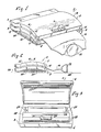
- the vacuum sealer 1 comprises a two-part housing, a lid 2 and a bottom housing 3.
- the bottom housing 3 has a bottom panel 4 that is removable (as shown in figure 5) to permit access to the interior of vacuum sealer 1.
- the sealer 1 has a low height or profile, substantially lower than the prior art units.
- low profile or “low height” is meant the bag exit opening 5 is from about 25 to 38 mm from the ground or support surface whereas prior art units have a bag exit of from about 63 to 100 mm.
- This low profile greatly improves the air flow from the sealer 1 to the interior of the bag 6 and prevents the top of the bag from sliding out of the sealer. There is a much straighter air flow path because of the low profile and tapered end 7 of the unit 1.
- Air exhaust ducts or outlets 10 are located on the side or preferably both sides of unit 1. Vents 10, however, can be located on any or all four sides of unit 1 and can be positioned in the side or sides of bottom housing 3, of panel 4 or of lid 2. These ducts 10 extend from the interior of the bottom portion 3 to the atmosphere. These ducts 10 allow a freer escape means for air from the interior of bottom portion 3.
- the curvature 8 of the lid and complementary curvature portion 11 of the bottom portion 3 provide a smooth path guide for the bag and permit much easier flow of air therefrom during the vacuum operation.
- the bag 6 is formed from plastic sheet material stored on a bag roll 16. In a preferred form, a length of plastic sheet material is folded longitudinally so that as it is unwound from the roll, one side is folded and the other side comprises two unjoined sheet edges.
- the leading end of the sheet material which has already been sealed in the previous bag-sealing operation, extends from the roll 16 inside unit 1 to the outside so that an object 12 can be placed in the bag before sealing the trailing end of the bag, which is shown still in between lid 2 and bottom portion 3 at opening 5.
- the bag 6 is then removed from the sealer, turned through a right angle, and sealed at its open side by merely placing the bag side to be sealed over the sealing wires (shown in Figures 3 and 4) and depressing the lid 2 gently down until the vacuum indicator light goes on.
- the air at this point will be drawn out of bag 6 as the spinning turbine in the interior causes a vacuum air flow effect through an air nozzle that is in air flow connection with the turbine and an air extraction nozzle, both to be later described.
- the vacuum effect operates on the same principle as a vacuum cleaner.
- FIG 2 a side view of unit 1 is shown as bag 6 extends out from unit opening 5.
- the curvatures or curved portions 8 and 11 of lid 2 and bottom housing 3, respectively, can be clearly seen.
- the smooth and relatively obstruction-free path of bag 6 can be seen because of these curvatures and the low profile of the unit 1 and opening 5.
- a bottom removable panel 4 is illustrated; this panel 4 can be removably attached to bottom housing 3 by any convenient means such as screws, bolts or other removable attachment means.
- Air ducts or vents 10 are shown on the side where they can facilitate easy exhausting of air from the interior of bottom housing 3.
- the relatively low height or low profile of unit 1 can be clearly seen in Figure 2.
- the air ducts 10, the tapered or low profile of unit 1 and the curved fins 21 provide a more effective air evacuation of bag 6. Also, the time required to evacuate the air from bag 6 is accordingly reduced substantially.
- FIG 3 the lid 2 is lifted to open unit 1 showing the three heated wires 13 located at the entrance to unit 1 at or near opening 5.
- an air extractor nozzle 14 Located behind wires 13 at a position approximately at the midpoint of opening 5 is an air extractor nozzle 14 which is used to extract the air from the interior of bag 6 during the vacuuming cycle or process.
- the nozzle 14 is inserted into the open end of bag 6 and the lid 2 closed and gently pressed down holding the open end of bag 6 with nozzle 14 inserted therein.
- a switch or starting mechanism is triggered off which causes a turbine to rotate and draw air out of the bag 6 via nozzle 14.
- Nozzle 14 is ribbed which allows air to be extracted more easily from the bag because it permits air to enter from both sides and front and uses ribs to create air channels toward the rear of the bag.
- the triple wire configuration 13 forms one seal in the leading end of the next subsequent bag on the roll 16 and another seal in the trailing end of the bag 6 to be presently used. This one operation thus creates two seals and prepares the next bag by the upper sealing wire 13 sealing one end of the next bag.
- the lower sealing wire is subsequently used to seal the open side of the bag 6 after it has been filled with object 12. These two seals can be accomplished since the sealer of the invention provides two dedicated sealing wires and one dedicated cutting wire. By providing two dedicated sealing wires, much stronger and more airtight seals are provided in bags 6.
- a curved bag guide 15 over which bag 6 extends from bag roll 16.
- the roundness of bag guide 15 avoids obstructions to air flow and also avoids damage to the bag because of a smooth and curved surface.
- the bag supply extends from a bag roll 16 located adjacent but behind curved bag guide 15. It is preferred, for optimum results, that the curved bag guide 15 is positioned in unit 1 at a point between nozzle 14 and bag roll 16 or a bag roll dispenser means.
- a silicon rubber bar 17 At the inner front portion of lid 2 is a silicon rubber bar 17 that mates with the three wires when the lid 2 is pressed down during the vacuuming operation. This rubber bar 17 is important because it presses the bag material into the sealing wires and fuses the bag layers together.
- FIG 4 the same open view as in Figure 3 is shown except in a side perspective.
- Lid 2 is shown fully opened upon hinge means 18 which may be any suitable hinge means.
- a bag roll cavity or depression 19 is provided for housing a roll 16 or supply of bags. This cavity 19 is formed immediately behind curved or rounded bag guide 15. Bag roll or supply housing or compartment 19 is tubular in order to accommodate a roll of plastic bags.
- the bag supply then extends over bag guide 15 for a smooth path unobstructed by any sharp corners or edges.
- the bag supply can be torn off having two sealed ends, a folded side and an open side.
- An object of food or other item or items are then placed into the open side of bag 6 and this open side then placed over wires 13 with nozzle 14 extending into the bag 6 through its open side.
- lid 2 is closed activating the sealing-vacuuming process where nozzle 14 draws air out of bag 6 because of the vacuum action initiated by closing lid 2. Since there is less vibration in unit 1 than in prior art units, it is much quieter when
- unit 1 is turned over so that removable panel 4 is facing upward. Screws are removed which previously had connected panel 4 to bottom housing 3. Once panel 4 has been removed the interior of housing 3 is exposed.
- the motor 20 can be any suitable power source such as a 110V-120V AC motor.
- turbine 24 rotates, its curved fins 21 suck air into the unit 1 and out of a bag 6 via air extraction nozzle 14.
- the curved fins 21 of this invention are preferred because without them a greatly reduced vacuum effect would be created.
- An air conduit extends from a point adjacent said turbine 24 to said air extraction nozzle 14 so that there is a free and unobstructed air path between turbine 24 and nozzle 14.
- Transformer 22 Located also in the hollow under bag guide 15 is transformer 22 which provides the energy to heat wires 13 upon demand as well as to the remainder of the circuit.
- Heating means 22 suitable for use are typically a transformer and circuit board with electronics such as that manufactured by Dyco Electronics of Hornell, NY.
- a wire 23 to be connected to a source of electrical energy can be connected to any suitable portion of unit 1 as desired.
- the hump 32 formed by the hollow or cavity 19 houses the roll of bags 16. All appropriate wire connections are made by wires or other suitable circuitry commonly used in devices of this type.
- FIG. 6 a comparison between the present invention air flow path (Fig. 6B) and the air flow path of prior art devices is illustrated.
- Figure 6A a prior art vacuum sealer is shown in side breakaway view.
- the bag roll 25 extends over a sharp guide 26 then over a relatively high corner 27 down for a considerable distance to a supporting surface or the ground 28.
- the several severe bends in the plastic bag source 29 are very evident.
- the air flow path in these prior art units is not straight and unencumbered as in the path of the bag shown in Figure 6B of the present invention.
- the bag 6 is shown with relatively little obstruction to a smooth air flow path while the prior art devices of Figure 6A do not provide this significant advantage.
- FIG. 6B air extraction nozzle 14 is shown inserted into the open end of bag 6.
- nozzle 14 draws all the air out of bag 6 and wires 13 seal and cut the bag after air has been evacuated therefrom.
- the air passages 34 are shown both in the front and sides of nozzle 14 for more complete air evacuation.
- these passages 34 and air vents 10 are preferred features of the present invention.
- Turbine 24 and motor 20 are shown in an enlarged view.
- Turbine 24 has curved vanes or fins 21 which generate a much greater air flow than straight fins and could enhance the vacuuming effect of this invention over 50% of prior art units. Also, the use of curved fins reduces the time required to evacuate air from the bag during the vacuum step. Any suitable number of fins 21 may be used depending upon the desired effect. It is preferred that at least four curved fins 21 be used and optimally six or more fins be used. Any suitable motor 20 may be used such as those manufactured by the Johnson Co. of Hong Kong.
Landscapes
- Engineering & Computer Science (AREA)
- Mechanical Engineering (AREA)
- Chemical & Material Sciences (AREA)
- Dispersion Chemistry (AREA)
- Vacuum Packaging (AREA)
- Secondary Cells (AREA)
- Lining Or Joining Of Plastics Or The Like (AREA)
- Sealing Material Composition (AREA)
- Bag Frames (AREA)
Priority Applications (1)
| Application Number | Priority Date | Filing Date | Title |
|---|---|---|---|
| AT90312148T ATE103237T1 (de) | 1990-05-09 | 1990-11-06 | Vakuumdichtungseinrichtung. |
Applications Claiming Priority (2)
| Application Number | Priority Date | Filing Date | Title |
|---|---|---|---|
| US520729 | 1990-05-09 | ||
| US07/520,729 US5048269A (en) | 1990-05-09 | 1990-05-09 | Vacuum sealer |
Publications (3)
| Publication Number | Publication Date |
|---|---|
| EP0455907A2 true EP0455907A2 (de) | 1991-11-13 |
| EP0455907A3 EP0455907A3 (en) | 1992-04-01 |
| EP0455907B1 EP0455907B1 (de) | 1994-03-23 |
Family
ID=24073837
Family Applications (1)
| Application Number | Title | Priority Date | Filing Date |
|---|---|---|---|
| EP90312148A Expired - Lifetime EP0455907B1 (de) | 1990-05-09 | 1990-11-06 | Vakuumdichtungseinrichtung |
Country Status (8)
| Country | Link |
|---|---|
| US (1) | US5048269A (de) |
| EP (1) | EP0455907B1 (de) |
| CN (1) | CN2083136U (de) |
| AT (1) | ATE103237T1 (de) |
| CA (1) | CA2019687C (de) |
| DE (1) | DE69007614T2 (de) |
| ES (1) | ES2050967T3 (de) |
| HK (1) | HK86694A (de) |
Cited By (4)
| Publication number | Priority date | Publication date | Assignee | Title |
|---|---|---|---|---|
| US5649407A (en) * | 1993-09-08 | 1997-07-22 | Tetra Laval Holdings & Finance S.A. | Apparatus for sealing thermoplastic-coated packaging material |
| EP1564148A3 (de) * | 2004-02-12 | 2006-05-03 | FLAEM NUOVA S.p.A. | Vorrichtung zum Erzeugen von Vacuum in Behältern zum Konservieren von Vacuum-verpackten Produkten |
| WO2007018411A1 (en) * | 2005-08-11 | 2007-02-15 | Eiffel Industry Co., Ltd. | Double push device and vacuum and packing apparatus having the same |
| WO2012060670A3 (ko) * | 2010-11-05 | 2012-07-26 | Lee Kyul-Joo | 진공 포장기 |
Families Citing this family (86)
| Publication number | Priority date | Publication date | Assignee | Title |
|---|---|---|---|---|
| USD328750S (en) | 1990-04-17 | 1992-08-18 | Shu-Hui Chou | Compact heat sealer |
| US5287029A (en) * | 1991-10-09 | 1994-02-15 | General Signal Corporation | Casing with integral mounting for an electric motor |
| USD341845S (en) | 1992-03-11 | 1993-11-30 | General Binding Corporation | Thermal binding unit |
| US5287680A (en) * | 1992-08-06 | 1994-02-22 | Specialite Industries Ltd. | Vacuum packing device |
| GB2275442A (en) * | 1993-02-25 | 1994-08-31 | Kwonnie Electrical Products Lt | Vacuum sealing plastics bags |
| US5352323A (en) * | 1993-10-20 | 1994-10-04 | Sunfa Plastic Co., Ltd. | Heat sealing apparatus |
| US5655357A (en) * | 1995-05-02 | 1997-08-12 | Tilia International, Inc. | Exhaust flow rate vacuum sensor |
| US5638664A (en) * | 1995-07-17 | 1997-06-17 | Hantover, Inc. | Vacuum packaging apparatus |
| USD396239S (en) | 1996-10-05 | 1998-07-21 | Wei-Min Hsieh | Shell-shaped Laminator |
| US5893822A (en) * | 1997-10-22 | 1999-04-13 | Keystone Mfg. Co., Inc. | System for vacuum evacuation and sealing of plastic bags |
| US20040082454A1 (en) * | 1999-01-19 | 2004-04-29 | White Philip L. | Dispenser and sealer for bags |
| JP2002534344A (ja) * | 1999-01-19 | 2002-10-15 | アスコム ハスラー メーリング システムズ インコーポレイテッド | 電子制御された封止テープ供出器及び方法 |
| JP2004519356A (ja) | 2001-02-21 | 2004-07-02 | イ、ゴルジュ | 流路を有する真空包装用フィルムの製造方法 |
| KR100383399B1 (ko) * | 2001-02-28 | 2003-05-12 | 이걸주 | 포터블 진공포장기 |
| US20020152281A1 (en) * | 2001-04-13 | 2002-10-17 | Ko-Chien Chuang | Online device and method for downloading and sharing information by one touch |
| US7270238B2 (en) * | 2001-04-17 | 2007-09-18 | Foodfresh Technologies, Llc | Vacuum sealable bag apparatus and method |
| US6991109B1 (en) | 2001-04-17 | 2006-01-31 | Foodfresh Technologies Llc | Vacuum sealable bag apparatus and method |
| US6467242B1 (en) * | 2001-05-14 | 2002-10-22 | Chiou Shiang Huang | Heat-sealing apparatus |
| US6694710B2 (en) * | 2001-12-14 | 2004-02-24 | Donglei Wang | Vacuum bag-sealing machine |
| KR100423877B1 (ko) * | 2002-02-01 | 2004-03-22 | 이걸주 | 진공포장기 |
| US20040004361A1 (en) * | 2002-07-05 | 2004-01-08 | Foster Karen Lynn | Scoop & seal |
| US20040007494A1 (en) * | 2002-07-15 | 2004-01-15 | Popeil Ronald M. | Apparatus and method to more effectively vacuum package foods and other objects |
| KR100456588B1 (ko) * | 2002-07-19 | 2004-11-10 | 삼성전자주식회사 | 실링기 |
| US7076929B2 (en) | 2002-10-04 | 2006-07-18 | Jcs/Thg, Llc | Appliance for vacuum sealing food containers |
| US7003928B2 (en) | 2002-10-04 | 2006-02-28 | Jcs/Thg, Llc | Appliance for vacuum sealing food containers |
| WO2004033315A2 (en) * | 2002-10-04 | 2004-04-22 | The Holmes Group, Inc. | Appliance for vacuum sealing food containers |
| US7131250B2 (en) | 2002-10-04 | 2006-11-07 | Jcs/Thg, Llp | Appliance for vacuum sealing food containers |
| ITVR20020132A1 (it) * | 2002-12-27 | 2004-06-28 | Tecla Di Schiro & Isotta S N C | Gruppo macchina operatrice - confezionatrice sotto vuoto. |
| US7204067B2 (en) | 2003-02-27 | 2007-04-17 | Sunbeam Products, Inc. | Vacuum packaging appliance with removable trough |
| US7207160B2 (en) * | 2003-02-27 | 2007-04-24 | Sunbeam Products, Inc. | Vacuum packaging appliance with vacuum side channel latches |
| US7138025B2 (en) | 2003-03-05 | 2006-11-21 | Tilia International, Inc. | Method for manufacturing a sealable bag having an integrated tray for use in vacuum packaging |
| US20050034806A1 (en) | 2003-03-05 | 2005-02-17 | Tilia International, Inc. | Method for manufacturing liquid-trapping bag for use in vacuum packaging |
| US7087130B2 (en) | 2003-03-05 | 2006-08-08 | Tilia International, Inc. | Method for manufacturing a sealable bag having an integrated zipper for use in vacuum packaging |
| US7517484B2 (en) | 2003-03-24 | 2009-04-14 | Sunbeam Products, Inc. | Forming evacuation channels during single and multi-layer extrusion process |
| CA104789S (en) * | 2003-05-13 | 2005-03-10 | Philip Zepter | Vacuum packaging device |
| US7021027B2 (en) * | 2003-07-29 | 2006-04-04 | Tilia International, Inc. | Vacuum pump control and vacuum feedback |
| US20050022480A1 (en) * | 2003-07-29 | 2005-02-03 | David Brakes | Vacuum packaging appliances including support assemblies for carrying bag material |
| US20050022474A1 (en) * | 2003-07-31 | 2005-02-03 | Albritton Charles Wade | Heat sealing element and control of same |
| US7200974B2 (en) | 2003-07-31 | 2007-04-10 | Sunbeam Products, Inc. | Lidless vacuum appliance |
| US7021034B2 (en) * | 2003-07-31 | 2006-04-04 | Tilia International, Inc. | Decoupled vacuum packaging appliance |
| US20050039420A1 (en) * | 2003-07-31 | 2005-02-24 | Albritton Charles Wade | Fluid sensing in a drip tray |
| US20050022473A1 (en) * | 2003-07-31 | 2005-02-03 | Small Steven D. | Removable drip trays and bag clamps for vacuum packaging appliances |
| US7478516B2 (en) | 2003-07-31 | 2009-01-20 | Sunbeam Products, Inc. | Vacuum packaging appliance |
| US7197861B2 (en) * | 2003-07-31 | 2007-04-03 | Sunbeam Products, Inc. | Vacuum packaging appliances |
| ITVR20030115A1 (it) * | 2003-10-01 | 2005-04-02 | Marziano Salvaro | Dispositivo per la creazione del vuoto almeno parziale |
| US7220053B2 (en) | 2003-12-16 | 2007-05-22 | Sunbeam Products, Inc. | Flexible composite bag for vacuum sealing |
| US20050220942A1 (en) * | 2004-03-15 | 2005-10-06 | Hongyu Wu | Easy to peal vacuum packaging bags |
| US7534039B2 (en) | 2004-07-22 | 2009-05-19 | Sunbeam Products, Inc. | Vacuum packaging films patterned with protruding cavernous structures |
| JP5468205B2 (ja) * | 2005-01-12 | 2014-04-09 | ウノヴォ,インコーポレーテッド | 容器から流体を抽出し、密封するための方法および装置 |
| US7146783B2 (en) * | 2005-03-18 | 2006-12-12 | Hantover, Inc. | Vacuum packaging machine |
| WO2006130384A2 (en) * | 2005-05-27 | 2006-12-07 | The Glad Products Company | Device and method for evacuating a storage bag |
| CN101033014B (zh) * | 2006-03-08 | 2010-11-17 | 光荣电业公司 | 真空密封装置 |
| US20080050482A1 (en) * | 2006-06-13 | 2008-02-28 | Eastman Outdoors, Inc. | Kit for and method of marinating uncooked food |
| US20080000204A1 (en) * | 2006-06-28 | 2008-01-03 | S.C. Johnson Home Storage, Inc. | Vacuum sealer apparatus and a film cartridge for a vacuum sealer and a means of operating the vacuum sealer and the film cartridge |
| KR100853750B1 (ko) * | 2007-03-12 | 2008-08-22 | 주식회사 락앤락 | 진공 포장기 |
| US20100180548A1 (en) * | 2007-09-28 | 2010-07-22 | Binger Scott W | Evacuable storage bag |
| EP2207720B1 (de) * | 2007-10-12 | 2017-06-28 | Pregis Innovative Packaging LLC | Aufblas- und dichtungsvorrichtung mit ausrückmechanismus |
| US8240158B2 (en) * | 2008-03-12 | 2012-08-14 | Whirlpool Corporation | Modified atmosphere for food preservation |
| US20110126986A1 (en) * | 2009-12-01 | 2011-06-02 | Po Ha Cheung | Easy-to-operate bag sealer |
| EP2521648B1 (de) * | 2010-01-06 | 2019-02-27 | Pregis Innovative Packaging LLC | Vorrichtung mit stromaufwärts vorgesehenen mitteln zur herstellung von luftkissen |
| EP2768736B1 (de) * | 2011-10-21 | 2016-12-07 | Sunbeam Products, Inc. | Vakuumverpackungs- und verschlussvorrichtung mit doppelversiegelung |
| US20150027089A1 (en) * | 2012-10-22 | 2015-01-29 | Sunbeam Products, Inc. | Vacuum Packaging and Sealing Appliance with Cooling Fan |
| CN103057743B (zh) * | 2013-01-30 | 2015-05-20 | 温州拓然电器股份有限公司 | 一种全自动真空包装机 |
| WO2015134764A1 (en) * | 2014-03-05 | 2015-09-11 | Sunbeam Products, Inc. | Food preservation appliance with food management system |
| AU357677S (en) * | 2014-03-07 | 2014-09-24 | Oak Lawn Marketing | Vacuum sealer |
| USD773543S1 (en) * | 2015-07-24 | 2016-12-06 | Eric Fan | Vacuum sealer |
| CN105150603A (zh) * | 2015-08-04 | 2015-12-16 | 全峰正 | 一种保鲜袋制作器 |
| USD788199S1 (en) * | 2015-12-15 | 2017-05-30 | Sunbeam Products, Inc. | Vacuum sealer |
| USD789431S1 (en) * | 2015-12-15 | 2017-06-13 | Sunbeam Products, Inc. | Vacuum sealer |
| US10934041B2 (en) | 2017-06-01 | 2021-03-02 | Bcc Product Development, L.L.C. | System and method for sealing a plastic enclosure |
| USD854065S1 (en) * | 2017-06-16 | 2019-07-16 | Sunbeam Products, Inc. | Vacuum sealer |
| US20190055042A1 (en) * | 2017-08-15 | 2019-02-21 | Hamilton Beach Brands, Inc. | Vacuum Sealer With Two-Stage Sealing |
| USD854594S1 (en) * | 2017-10-11 | 2019-07-23 | The Metal Ware Corporation | Vacuum sealer |
| USD871470S1 (en) * | 2017-10-20 | 2019-12-31 | Shenzhen Green Electrical Appliance Co., Ltd | Vacuum sealer |
| CN109625453B (zh) * | 2018-11-27 | 2020-12-11 | 杭州煜贤网络科技有限公司 | 一种水平缩小配合三连波浪封口的鸭嘴塑料袋热封装置 |
| US20220002063A1 (en) * | 2019-02-09 | 2022-01-06 | Brian Keith McKinnon | Cooler System |
| US11772333B2 (en) | 2019-03-01 | 2023-10-03 | Brainchild Concepts, Llc | System and method for sealing a plastic enclosure |
| USD921730S1 (en) * | 2019-04-29 | 2021-06-08 | KunHua Chen | Vacuum sealer |
| USD939002S1 (en) * | 2019-05-13 | 2021-12-21 | Sunbeam Products, Inc. | Vacuum sealer |
| USD952716S1 (en) * | 2019-05-13 | 2022-05-24 | Sunbeam Products, Inc. | Vacuum sealer |
| USD926849S1 (en) * | 2019-08-28 | 2021-08-03 | Sunbeam Products, Inc. | Vacuum sealer |
| USD936120S1 (en) * | 2019-11-01 | 2021-11-16 | Freshkeep Ltd | Food vacuum device |
| USD905772S1 (en) * | 2019-11-21 | 2020-12-22 | Aukey Technology Co., Ltd | Laminating machine |
| EP3838778A1 (de) * | 2019-12-20 | 2021-06-23 | Vestel Elektronik Sanayi ve Ticaret A.S. | Vorrichtung und verfahren zur abdichtung eines vakuumbeutels |
| US11753196B2 (en) | 2020-11-11 | 2023-09-12 | Hamilton Beach Brands, Inc. | Vacuum sealer and method of sealing same |
| CN113022935A (zh) * | 2021-01-15 | 2021-06-25 | 深圳市鸿楷实业有限公司 | 一种便于使用的抽真空保鲜封口机 |
Family Cites Families (17)
| Publication number | Priority date | Publication date | Assignee | Title |
|---|---|---|---|---|
| US2749686A (en) * | 1951-09-26 | 1956-06-12 | Emhart Mfg Co | Vacuum packaging machine |
| US3234072A (en) * | 1962-06-27 | 1966-02-08 | Mercury Heat Sealing Equipment | Forming and sealing packages |
| US3458966A (en) * | 1966-03-24 | 1969-08-05 | Owens Corning Fiberglass Corp | Method of packaging compressible material |
| US3518809A (en) * | 1968-02-07 | 1970-07-07 | Hesser Ag Maschf | Apparatus for making and filling bags |
| US3969039A (en) * | 1974-08-01 | 1976-07-13 | American Optical Corporation | Vacuum pump |
| DE2618581A1 (de) * | 1976-04-28 | 1977-11-10 | Brocke Kg I B S | Folienschweissgeraet |
| US4115182A (en) * | 1977-06-29 | 1978-09-19 | Arenco Machine Company | Sealing means |
| YU253277A (en) * | 1977-10-21 | 1982-10-31 | Atelsek Ivan | Household apparatus for closing plastic bags filled with fodstuffs by welding at simultaneously exhausting air |
| IT1160587B (it) * | 1978-08-11 | 1987-03-11 | Fiap Srl | Procedimento per confezionare prodotti alimentari sotto vuoto |
| DE2938427A1 (de) * | 1979-09-22 | 1981-04-16 | Ibs Brocke Gmbh & Co Kg, 5222 Morsbach | Folienschweissgeraet |
| US4330975A (en) * | 1980-08-05 | 1982-05-25 | Kunio Kakiuchi | Simplified vacuum-package sealer apparatus |
| DE3203951C2 (de) * | 1982-02-05 | 1986-07-17 | Petra-Electric Peter Hohlfeldt Gmbh & Co, 8872 Burgau | Verfahren und Vorrichtung zum Evakuieren und anschließenden Verschweißen gefüllter Folienbeutel |
| YU43792B (en) * | 1982-04-01 | 1989-12-31 | Gorenje | Apparatus for welding plastic foils |
| DE3312780A1 (de) * | 1983-04-09 | 1984-10-11 | Robert Krups Stiftung & Co KG, 5650 Solingen | Folienschweissgeraet fuer haushaltfolienbeutel |
| US4598531A (en) * | 1984-07-20 | 1986-07-08 | Clik-Cut, Inc. | Sheet material dispenser and methods of dispensing sheet material and of wrapping items |
| US4860523A (en) * | 1986-10-31 | 1989-08-29 | Sharp Kabushiki Kaisha | Hermetic packaging apparatus |
| US4941310A (en) * | 1989-03-31 | 1990-07-17 | Tillia Aktiengesellschaft | Apparatus for vacuum sealing plastic bags |
-
1990
- 1990-05-09 US US07/520,729 patent/US5048269A/en not_active Expired - Lifetime
- 1990-06-22 CA CA002019687A patent/CA2019687C/en not_active Expired - Fee Related
- 1990-07-13 CN CN90216393U patent/CN2083136U/zh not_active Expired - Lifetime
- 1990-11-06 AT AT90312148T patent/ATE103237T1/de not_active IP Right Cessation
- 1990-11-06 ES ES90312148T patent/ES2050967T3/es not_active Expired - Lifetime
- 1990-11-06 EP EP90312148A patent/EP0455907B1/de not_active Expired - Lifetime
- 1990-11-06 DE DE69007614T patent/DE69007614T2/de not_active Expired - Fee Related
-
1994
- 1994-08-25 HK HK86694A patent/HK86694A/en not_active IP Right Cessation
Cited By (4)
| Publication number | Priority date | Publication date | Assignee | Title |
|---|---|---|---|---|
| US5649407A (en) * | 1993-09-08 | 1997-07-22 | Tetra Laval Holdings & Finance S.A. | Apparatus for sealing thermoplastic-coated packaging material |
| EP1564148A3 (de) * | 2004-02-12 | 2006-05-03 | FLAEM NUOVA S.p.A. | Vorrichtung zum Erzeugen von Vacuum in Behältern zum Konservieren von Vacuum-verpackten Produkten |
| WO2007018411A1 (en) * | 2005-08-11 | 2007-02-15 | Eiffel Industry Co., Ltd. | Double push device and vacuum and packing apparatus having the same |
| WO2012060670A3 (ko) * | 2010-11-05 | 2012-07-26 | Lee Kyul-Joo | 진공 포장기 |
Also Published As
| Publication number | Publication date |
|---|---|
| EP0455907A3 (en) | 1992-04-01 |
| ATE103237T1 (de) | 1994-04-15 |
| EP0455907B1 (de) | 1994-03-23 |
| CN2083136U (zh) | 1991-08-21 |
| DE69007614T2 (de) | 1994-07-07 |
| CA2019687A1 (en) | 1991-11-09 |
| DE69007614D1 (de) | 1994-04-28 |
| CA2019687C (en) | 1995-07-18 |
| ES2050967T3 (es) | 1994-06-01 |
| US5048269A (en) | 1991-09-17 |
| HK86694A (en) | 1994-09-02 |
Similar Documents
| Publication | Publication Date | Title |
|---|---|---|
| EP0455907B1 (de) | Vakuumdichtungseinrichtung | |
| US5893822A (en) | System for vacuum evacuation and sealing of plastic bags | |
| US7207160B2 (en) | Vacuum packaging appliance with vacuum side channel latches | |
| EP2768736B1 (de) | Vakuumverpackungs- und verschlussvorrichtung mit doppelversiegelung | |
| US7040074B2 (en) | Vacuum packaging apparatus and method | |
| US20150027089A1 (en) | Vacuum Packaging and Sealing Appliance with Cooling Fan | |
| EP0535747B1 (de) | Maschine zum Verpacken mittels einer, mit einer einzigen Falte versehener Schrumpffolie, mit einer Vorrichtung zum selbsttätigen Öffnen der Folie | |
| KR102383595B1 (ko) | 식품 용기 진공 스킨 포장장치 | |
| CN211167652U (zh) | 一种真空封口机 | |
| CN203642257U (zh) | 一种蒸箱微波炉一体机 | |
| GB2275442A (en) | Vacuum sealing plastics bags | |
| CN108061445A (zh) | 一种用于陈皮加工的烘干装置 | |
| US4746060A (en) | Popped corn receptacle | |
| PL188416B1 (pl) | Urządzenie do pakowania wyrobów w folię z materiału termokurczliwego | |
| EP3009255B1 (de) | Vakuumverpackungs- und siegelvorrichtung mit kühlgebläse | |
| CN210784081U (zh) | 一体化的破壁料理机 | |
| KR100900506B1 (ko) | 휴대용 진공 전열 씰러 | |
| KR20050054740A (ko) | 공기 하향 배출식 진공포장기 | |
| CN209415978U (zh) | 一种包装袋风暴干燥流水线 | |
| CN219565735U (zh) | 一种热收缩包装机 | |
| US4043096A (en) | Automatic packaging method and apparatus | |
| KR100421195B1 (ko) | 엠보싱 형성 수단이 장착된 진공포장기 | |
| CN113974356B (zh) | 具有抽真空包装功能的抽屉 | |
| CN2184544Y (zh) | 小型多功能真空封切机 | |
| JPH0720002Y2 (ja) | 電気掃除機を利用した簡易脱気包装機 |
Legal Events
| Date | Code | Title | Description |
|---|---|---|---|
| PUAI | Public reference made under article 153(3) epc to a published international application that has entered the european phase |
Free format text: ORIGINAL CODE: 0009012 |
|
| AK | Designated contracting states |
Kind code of ref document: A2 Designated state(s): AT BE CH DE ES FR GB IT LI SE |
|
| PUAL | Search report despatched |
Free format text: ORIGINAL CODE: 0009013 |
|
| AK | Designated contracting states |
Kind code of ref document: A3 Designated state(s): AT BE CH DE ES FR GB IT LI SE |
|
| 17P | Request for examination filed |
Effective date: 19920709 |
|
| 17Q | First examination report despatched |
Effective date: 19930408 |
|
| GRAA | (expected) grant |
Free format text: ORIGINAL CODE: 0009210 |
|
| AK | Designated contracting states |
Kind code of ref document: B1 Designated state(s): AT BE CH DE ES FR GB IT LI SE |
|
| REF | Corresponds to: |
Ref document number: 103237 Country of ref document: AT Date of ref document: 19940415 Kind code of ref document: T |
|
| REF | Corresponds to: |
Ref document number: 69007614 Country of ref document: DE Date of ref document: 19940428 |
|
| ET | Fr: translation filed | ||
| ITF | It: translation for a ep patent filed | ||
| REG | Reference to a national code |
Ref country code: ES Ref legal event code: FG2A Ref document number: 2050967 Country of ref document: ES Kind code of ref document: T3 |
|
| PLBE | No opposition filed within time limit |
Free format text: ORIGINAL CODE: 0009261 |
|
| STAA | Information on the status of an ep patent application or granted ep patent |
Free format text: STATUS: NO OPPOSITION FILED WITHIN TIME LIMIT |
|
| EAL | Se: european patent in force in sweden |
Ref document number: 90312148.1 |
|
| 26N | No opposition filed | ||
| REG | Reference to a national code |
Ref country code: GB Ref legal event code: IF02 |
|
| PGFP | Annual fee paid to national office [announced via postgrant information from national office to epo] |
Ref country code: SE Payment date: 20021108 Year of fee payment: 13 |
|
| PGFP | Annual fee paid to national office [announced via postgrant information from national office to epo] |
Ref country code: ES Payment date: 20021111 Year of fee payment: 13 |
|
| PGFP | Annual fee paid to national office [announced via postgrant information from national office to epo] |
Ref country code: AT Payment date: 20021128 Year of fee payment: 13 Ref country code: CH Payment date: 20021128 Year of fee payment: 13 |
|
| PGFP | Annual fee paid to national office [announced via postgrant information from national office to epo] |
Ref country code: BE Payment date: 20021212 Year of fee payment: 13 |
|
| PG25 | Lapsed in a contracting state [announced via postgrant information from national office to epo] |
Ref country code: AT Free format text: LAPSE BECAUSE OF NON-PAYMENT OF DUE FEES Effective date: 20031106 |
|
| PG25 | Lapsed in a contracting state [announced via postgrant information from national office to epo] |
Ref country code: SE Free format text: LAPSE BECAUSE OF NON-PAYMENT OF DUE FEES Effective date: 20031107 Ref country code: ES Free format text: LAPSE BECAUSE OF NON-PAYMENT OF DUE FEES Effective date: 20031107 |
|
| PG25 | Lapsed in a contracting state [announced via postgrant information from national office to epo] |
Ref country code: LI Free format text: LAPSE BECAUSE OF NON-PAYMENT OF DUE FEES Effective date: 20031130 Ref country code: CH Free format text: LAPSE BECAUSE OF NON-PAYMENT OF DUE FEES Effective date: 20031130 Ref country code: BE Free format text: LAPSE BECAUSE OF NON-PAYMENT OF DUE FEES Effective date: 20031130 |
|
| BERE | Be: lapsed |
Owner name: *DENI FRANK Effective date: 20031130 |
|
| EUG | Se: european patent has lapsed | ||
| REG | Reference to a national code |
Ref country code: CH Ref legal event code: PL |
|
| PGFP | Annual fee paid to national office [announced via postgrant information from national office to epo] |
Ref country code: FR Payment date: 20041123 Year of fee payment: 15 |
|
| REG | Reference to a national code |
Ref country code: ES Ref legal event code: FD2A Effective date: 20031107 |
|
| PG25 | Lapsed in a contracting state [announced via postgrant information from national office to epo] |
Ref country code: IT Free format text: LAPSE BECAUSE OF NON-PAYMENT OF DUE FEES;WARNING: LAPSES OF ITALIAN PATENTS WITH EFFECTIVE DATE BEFORE 2007 MAY HAVE OCCURRED AT ANY TIME BEFORE 2007. THE CORRECT EFFECTIVE DATE MAY BE DIFFERENT FROM THE ONE RECORDED. Effective date: 20051106 |
|
| PGFP | Annual fee paid to national office [announced via postgrant information from national office to epo] |
Ref country code: DE Payment date: 20051110 Year of fee payment: 16 |
|
| PGFP | Annual fee paid to national office [announced via postgrant information from national office to epo] |
Ref country code: GB Payment date: 20051121 Year of fee payment: 16 |
|
| PG25 | Lapsed in a contracting state [announced via postgrant information from national office to epo] |
Ref country code: FR Free format text: LAPSE BECAUSE OF NON-PAYMENT OF DUE FEES Effective date: 20060731 |
|
| REG | Reference to a national code |
Ref country code: FR Ref legal event code: ST Effective date: 20060731 |
|
| PG25 | Lapsed in a contracting state [announced via postgrant information from national office to epo] |
Ref country code: DE Free format text: LAPSE BECAUSE OF NON-PAYMENT OF DUE FEES Effective date: 20070601 |
|
| GBPC | Gb: european patent ceased through non-payment of renewal fee |
Effective date: 20061106 |
|
| PG25 | Lapsed in a contracting state [announced via postgrant information from national office to epo] |
Ref country code: GB Free format text: LAPSE BECAUSE OF NON-PAYMENT OF DUE FEES Effective date: 20061106 |