EP0455840A1 - Verbrennungsanlage und Verfahren zur Vernichtung von Sonderabfällen - Google Patents
Verbrennungsanlage und Verfahren zur Vernichtung von Sonderabfällen Download PDFInfo
- Publication number
- EP0455840A1 EP0455840A1 EP90106597A EP90106597A EP0455840A1 EP 0455840 A1 EP0455840 A1 EP 0455840A1 EP 90106597 A EP90106597 A EP 90106597A EP 90106597 A EP90106597 A EP 90106597A EP 0455840 A1 EP0455840 A1 EP 0455840A1
- Authority
- EP
- European Patent Office
- Prior art keywords
- combustion
- incinerator
- air
- housing
- heat exchanger
- Prior art date
- Legal status (The legal status is an assumption and is not a legal conclusion. Google has not performed a legal analysis and makes no representation as to the accuracy of the status listed.)
- Ceased
Links
Images
Classifications
-
- F—MECHANICAL ENGINEERING; LIGHTING; HEATING; WEAPONS; BLASTING
- F28—HEAT EXCHANGE IN GENERAL
- F28D—HEAT-EXCHANGE APPARATUS, NOT PROVIDED FOR IN ANOTHER SUBCLASS, IN WHICH THE HEAT-EXCHANGE MEDIA DO NOT COME INTO DIRECT CONTACT
- F28D7/00—Heat-exchange apparatus having stationary tubular conduit assemblies for both heat-exchange media, the media being in contact with different sides of a conduit wall
- F28D7/0041—Heat-exchange apparatus having stationary tubular conduit assemblies for both heat-exchange media, the media being in contact with different sides of a conduit wall the conduits for only one medium being tubes having parts touching each other or tubes assembled in panel form
-
- F—MECHANICAL ENGINEERING; LIGHTING; HEATING; WEAPONS; BLASTING
- F23—COMBUSTION APPARATUS; COMBUSTION PROCESSES
- F23G—CREMATION FURNACES; CONSUMING WASTE PRODUCTS BY COMBUSTION
- F23G5/00—Incineration of waste; Incinerator constructions; Details, accessories or control therefor
- F23G5/008—Incineration of waste; Incinerator constructions; Details, accessories or control therefor adapted for burning two or more kinds, e.g. liquid and solid, of waste being fed through separate inlets
-
- F—MECHANICAL ENGINEERING; LIGHTING; HEATING; WEAPONS; BLASTING
- F23—COMBUSTION APPARATUS; COMBUSTION PROCESSES
- F23G—CREMATION FURNACES; CONSUMING WASTE PRODUCTS BY COMBUSTION
- F23G5/00—Incineration of waste; Incinerator constructions; Details, accessories or control therefor
- F23G5/08—Incineration of waste; Incinerator constructions; Details, accessories or control therefor having supplementary heating
- F23G5/12—Incineration of waste; Incinerator constructions; Details, accessories or control therefor having supplementary heating using gaseous or liquid fuel
-
- F—MECHANICAL ENGINEERING; LIGHTING; HEATING; WEAPONS; BLASTING
- F23—COMBUSTION APPARATUS; COMBUSTION PROCESSES
- F23G—CREMATION FURNACES; CONSUMING WASTE PRODUCTS BY COMBUSTION
- F23G5/00—Incineration of waste; Incinerator constructions; Details, accessories or control therefor
- F23G5/50—Control or safety arrangements
-
- F—MECHANICAL ENGINEERING; LIGHTING; HEATING; WEAPONS; BLASTING
- F23—COMBUSTION APPARATUS; COMBUSTION PROCESSES
- F23M—CASINGS, LININGS, WALLS OR DOORS SPECIALLY ADAPTED FOR COMBUSTION CHAMBERS, e.g. FIREBRIDGES; DEVICES FOR DEFLECTING AIR, FLAMES OR COMBUSTION PRODUCTS IN COMBUSTION CHAMBERS; SAFETY ARRANGEMENTS SPECIALLY ADAPTED FOR COMBUSTION APPARATUS; DETAILS OF COMBUSTION CHAMBERS, NOT OTHERWISE PROVIDED FOR
- F23M5/00—Casings; Linings; Walls
- F23M5/08—Cooling thereof; Tube walls
- F23M5/085—Cooling thereof; Tube walls using air or other gas as the cooling medium
-
- F—MECHANICAL ENGINEERING; LIGHTING; HEATING; WEAPONS; BLASTING
- F23—COMBUSTION APPARATUS; COMBUSTION PROCESSES
- F23G—CREMATION FURNACES; CONSUMING WASTE PRODUCTS BY COMBUSTION
- F23G2207/00—Control
- F23G2207/10—Arrangement of sensing devices
- F23G2207/101—Arrangement of sensing devices for temperature
-
- F—MECHANICAL ENGINEERING; LIGHTING; HEATING; WEAPONS; BLASTING
- F23—COMBUSTION APPARATUS; COMBUSTION PROCESSES
- F23G—CREMATION FURNACES; CONSUMING WASTE PRODUCTS BY COMBUSTION
- F23G2207/00—Control
- F23G2207/40—Supplementary heat supply
Definitions
- the present invention generally relates to waste and hazardous materials and, more particularly, to an improved method and apparatus for completely incinerating such materials.
- Hazardous materials and waste materials represent a serious challenge to human and animal health and to the environment in general. Recently, concerted efforts have been made to dispose of such materials in a safe manner, in many cases by dumping them in deep land fill zones. In other cases, hazardous materials are encased in protective containers and buried in land fills or at sea. Certain hazardous materials are also disposed of by burning them at trash dumps, in commercial furnaces and the like. Depending on the burning parameters, such destruction frequently is time-consuming, incomplete and produces noxious levels of undesired pollutants.
- the improved method and waste incinerator of the present invention satisfy all of the foregoing needs.
- the incinerator is a sudden expansion burner such as is currently used to produce high temperature gases for commercial heating and treating processes and testing facilities.
- One such burner is illustrated and described in U.S. Patent No. 3,074,469.
- the present inventors have discovered that such a gas-generating burner can be successfully used to completely consume hazardous and non-hazardous fluidized waste without producing noxious by-products such as nitrogen oxides and similar pollutants.
- U.S. Patent No. 4,785,748 discloses an incinerator invented by the present inventors which successfully consumes fluidized waste material. Further significant efficiency of operation is now provided by the present incinerator and method.
- fluidized waste to be burned is injected as a stream into the front end of the incinerator through the small diameter cylindrical pipe inlet thereof and passes through that pipe, together with air heated by an annular heat exchanger in the form of a spaced bundle of heated charged tubes and blown to the inlet pipe. If the waste comprises fumes or a mass of small particles, it is entrained in air added to the fluidized waste supply line.
- the inlet pipe is concentric with and connected to the larger diameter cylindrical combustion chamber by a circular flat plate through which one or more fuel injection nozzles extend into the combustion chamber. The rear end of the combustion chamber is open.
- the device also includes an electrically powered igniter extending through the pipe inlet to the combustion chamber and supplied with igniter fuel. Controls are provided for the igniter, air, fuel and waste supply systems.
- the air blower of the device communicates through the outer concentric tubular housing of the device with an air passageway in which the heat exchanger is disposed.
- the tubes thereof are open ended so that waste gases flow therethrough from the rear to the front of the tubes for exhausting through a front stack in the heat exchange with the front blower.
- the combustion chamber is inside the heat exchanger.
- Fuel is supplied to the upstream end of the combustion chamber. If the waste is a liquid or gas capable of sustaining combustion at more than 5000 BTU/lb., it can be premixed with the fuel and injected therewith, rather than separately .
- the sudden expansion between the smaller inlet pipe and the combustion chamber has the effect of acting as a flame holder, permitting stable and complete combustion of waste and fuel in the incinerator without generating products of incomplete combustion (PIC's) in significant concentrations.
- PIC's incomplete combustion
- the fuel, air and waste, while being consumed, pass entirely through the elongated combustion chamber from the overstoichiometric area thereof to an understoichiometric downstream area. Highly reactive ions are generated in the combustion process to facilitate the more rapid and complete incineration of waste than in previous methods. Since the incoming air is heated more efficiently, less fuel is used than in the incinerator of U.S. Patent No. 4,785,478 and less waste gas is generated.
- the incinerator can be of any suitable size and shape capable of producing the desired results, for example, a concentric tubular array, with the combustion chamber having an inlet pipe as small as 3 inches in diameter, the combustion chamber being 6 inches in diameter; or an inlet pipe larger than 20 inches in diameter, the combustion chamber being 40 inches in diameter.
- the overall combustion chamber and/or incinerator length can range from 1 to 30 feet in length.
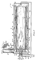
- incinerator 10 which comprises an outer hollow, tubular, preferably cylindrical, housing 12 of steel or the like high temperature metal or ceramic within which is releasably disposed a tubular heat exchanger 14 best seen in Figures 2 and 3. Inside heat exchanger 14 is disposed a hollow tubular combustion chamber 16. The components 12, 14 and 16 may be welded together.
- Housing 12 comprises a cylindrical side wall 18 and closed front and rear end walls 20 and 22.
- the inlet duct 24 of an air blower 26 is disposed through sidewalls 18 adjacent front end 20.
- An exhaust gas stack 28 extends through sidewalls 18 in front of duct 24 and preferably in heat exchange therewith, so that exhaust gases 30 passing out through stack 28 are cooled by and heat air passing into incinerator 10 through duct 24 from blower 26.
- Heat exchanger 16 is spaced inwardly of sidewall 18, as by one or more porous spacer rings 32 ( Figures 1, 2 and 3) or the like, so as to define an annular passageway 34 between sidewall 18 and heat exchanger 16, with which passageway duct 24 communicates.
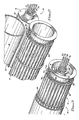
- Heat exchanger 16 comprises an annular bundle of separate, longitudinally extending, hollow, open ended thin, metallic tubes 36 of aluminum, copper, steel or the like, held spaced apart, as by ring 52 and front and rear collars 38 attached to tubes 36, so that air from passageway 34 can freely circulate therearound for maximum heat exchange therein.
- Heat exchanger 14 also includes a front extension tube 40 connected to front collar 38 and also connected to a second front collar 42 forward of collar 38.
- Front collars 38 and 42 and tube 40 may be integral. They define an annular groove 44 aligned with exhaust gas duct 28, allowing exhaust gases 30 to freely pass from the front ends 45 of tubes 36 through groove 44 to exhaust stack 28 and out of incinerator 10.
- Combustion chamber 16 comprises an elongated hollow cylindrical steel or other high temperature metal tube 46 with open front inlet end 48 and rear outlet end 50.
- Front end 48 has a concentric necked down front pipe portion 52 just upstream of the combustion zone 54 in tube 46.
- Tube 46 is slidably received without heat exchanger 14 and, like heat exchanger 14, is spaced forwardly of rear wall 22, and rearwardly of front wall 20, as shown in Figure 1.
- exhaust gases 30 from combustion zone 54 pass rearwardly out end 50 and into the rear ends 58 of heat exchanger tubes 36, then forwardly therein for exiting front ends 45 of tubes 36.
- Incinerator 10 also includes supply and central means. Thus, it has a fuel supply line 60 running from a remote source into and through inlet end 48 and into combustion zone 54.
- Line 60 is interconnected to a thermocouple 62 in the rear of incinerator 10 by a line 64 running to a central valve 66 on line 60, so that the flow rate of fuel in line 60 is regulated in response to the temperature indicated by the thermocouple 62.
- An igniter fuel supply line 68 also runs from a remote source into combustion zone 54 through inlet 48, along with the igniter tip 69 of electrically powered igniter device 70, and one or more fluidized waste material supply lines 72 and 74.
- the fuel in line 60 can be a hydrocarbon such as propane or the like, as can the fuel in line 68.
- Incinerator 10 is operated in accordance with the present method.
- incinerator 10 is started up by supplying igniter fuel through line 68 to combustion zone 54 and igniting it via tip 69 of device 70, while also supplying fuel through line 60 and fluidized waste material through line(s) 72 and/or 74 to zone 54.
- Air is supplied to zone 54 by operating blower 26, the air first flowing through duct 24 into passageway 34 and around heat exchanger tubes 36, and then forward thereof into and through inlet 48 to initiate and sustain the combustion.
- the flow of fuel through line 60 is regulated by valve 66 in response to thermocouple 62, as previously indicated.
- the hot exhaust gases 30 passing rearwardly in tube 46 and forwardly in tubes 36 heat the fresh incoming air from blower 26 so as to reduce the fuel necessary for the combustion reaction.
- the exhaust gases 30 may also heat exchange with the air in duct 24.
- air is delivered to combustion zone 54 at a flow rate for an incinerator having a combustion chamber of about 12" diameter x 120" length, of about 800-1400 cu.ft./min.
- the air flow rate and the waste material flow rate will vary according to the nature of the waste material, and the size and operating conditions of incinerator 10.
- Fuel such as methane, acetylene and other hydrocarbons can be used in addition to or in place of propane and can be supplied at any suitable flow rate, e.g., about 1.4-3.0 lbs./min. Because the incoming air to combustion zone 54 is highly heated, once combustion is underway, less fuel is used than was previously.
- Incinerator 10 is capable of self-sustaining combustion, particularly in view of the highly heated air, when the fluidized waste material to be consumed has a sufficiently high combustion heat output.
- Waste materials consumed by the incinerator can also include particles entrained in liquid and/or gases.
- Hazardous materials referred to herein can include any and all hazardous waste solid, liquid and gas materials, as well as hazardous materials it is desired to destroy, although they may not normally be considered as waste materials. The following specific examples illustrate certain features of the invention.
- the incinerator is constructed as shown with the drawings and is all steel.
- the combustion chamber is a cylinder 12 inches in diameter x 120 inches long, with a 12" long necked down front portion which is 6 inches in diameter.
- Air passes into the combustion zone at a rate of about 1250 cu.ft./min., while propane passes to that zone initially at about 2.5 cu.ft./min. and later at a lower flow rate.
- the fuel-air mixture is ignited by a propane gas flame from an igniter.
- waste gas is passed into the combustion zone at the rate of about 1-5 lbs./min. Residence time of the waste material therein is about 0.12 seconds, with an average combustion temperature of about 2000°F.
- the method and apparatus are safe, simple, inexpensive, durable and efficient.
- Waste fluid capable of sustaining combustion at more than 5000 BTU/lb. is passed into the combustion zone, along with propane at an initial flow rate of about 5 lbs./min. and air at a flow rate of about 3500 cu.ft./min.
- the waste residence time is about 0.12 seconds and the combustion temperature is about 2000°F.
- the fuel flow rate is gradually decreased and then stopped after combustion is fully sustained by the waste material, which combustion is aided greatly by the highly heated incoming air which has heat exchanged with the waste gases in the heat exchanger tubes and exhaust stack, the latter in heat exchange with the air inlet duct.
Landscapes
- Engineering & Computer Science (AREA)
- Mechanical Engineering (AREA)
- General Engineering & Computer Science (AREA)
- Chemical & Material Sciences (AREA)
- Combustion & Propulsion (AREA)
- Physics & Mathematics (AREA)
- Thermal Sciences (AREA)
- Air Supply (AREA)
Applications Claiming Priority (1)
| Application Number | Priority Date | Filing Date | Title |
|---|---|---|---|
| US07/369,880 US4915038A (en) | 1989-06-22 | 1989-06-22 | Sudden expansion (SUE) incinerator for destroying hazardous materials and wastes and improved method |
Publications (1)
| Publication Number | Publication Date |
|---|---|
| EP0455840A1 true EP0455840A1 (de) | 1991-11-13 |
Family
ID=23457302
Family Applications (1)
| Application Number | Title | Priority Date | Filing Date |
|---|---|---|---|
| EP90106597A Ceased EP0455840A1 (de) | 1989-06-22 | 1990-04-06 | Verbrennungsanlage und Verfahren zur Vernichtung von Sonderabfällen |
Country Status (2)
| Country | Link |
|---|---|
| US (1) | US4915038A (de) |
| EP (1) | EP0455840A1 (de) |
Families Citing this family (21)
| Publication number | Priority date | Publication date | Assignee | Title |
|---|---|---|---|---|
| US4915038A (en) * | 1989-06-22 | 1990-04-10 | The Marquardt Company | Sudden expansion (SUE) incinerator for destroying hazardous materials and wastes and improved method |
| US5216968A (en) * | 1990-11-09 | 1993-06-08 | Bayer Aktiengesellschaft | Method of stabilizing a combustion process |
| US5188042A (en) * | 1991-04-18 | 1993-02-23 | Praxair Technology, Inc. | Fluid waste burner system |
| US5129335A (en) * | 1991-04-18 | 1992-07-14 | Union Carbide Industrial Gases Technology Corporation | Fluid waste burner system |
| US5242245A (en) * | 1991-08-22 | 1993-09-07 | Schellstede Herman J | Method and apparatus for vacuum enhanced thermal desorption of hydrocarbon and other contaminants from soils |
| US5271340A (en) * | 1991-11-05 | 1993-12-21 | Rineco Chemical Industries | Apparatus and methods for burning waste, and waste slurries |
| US5374403A (en) * | 1993-07-13 | 1994-12-20 | The United States Of America As Represented By The United States Department Of Energy | Apparatus for incinerating hazardous waste |
| US5572866A (en) * | 1994-04-29 | 1996-11-12 | Environmental Thermal Oxidizers, Inc. | Pollution abatement incinerator system |
| JP3940973B2 (ja) * | 1997-11-28 | 2007-07-04 | 関東冶金工業株式会社 | 被加熱処理物から油性分の可燃分を除去する方法と装置 |
| DE19858120A1 (de) * | 1998-12-16 | 2000-06-21 | Basf Ag | Verfahren zur thermischen Behandlung von nicht brennbaren Flüssigkeiten |
| KR100729253B1 (ko) * | 1999-11-02 | 2007-06-15 | 가부시키가이샤 에바라 세이사꾸쇼 | 배기가스처리용 연소기 |
| US6321743B1 (en) * | 2000-06-29 | 2001-11-27 | Institute Of Gas Technology | Single-ended self-recuperated radiant tube annulus system |
| US6546883B1 (en) * | 2000-07-14 | 2003-04-15 | Rgf, Inc. | Thermo-oxidizer evaporator |
| US7160566B2 (en) * | 2003-02-07 | 2007-01-09 | Boc, Inc. | Food surface sanitation tunnel |
| US6916172B2 (en) * | 2003-08-25 | 2005-07-12 | L & S Cryogenics, Inc. | Burner apparatus |
| US7270539B1 (en) * | 2003-10-28 | 2007-09-18 | Soil-Therm Equipment, Inc. | Method and apparatus for destruction of vapors and waste streams using flash oxidation |
| US7273366B1 (en) * | 2003-10-28 | 2007-09-25 | Soil-Therm Equipment, Inc. | Method and apparatus for destruction of vapors and waste streams |
| US7028478B2 (en) * | 2003-12-16 | 2006-04-18 | Advanced Combustion Energy Systems, Inc. | Method and apparatus for the production of energy |
| JP4807076B2 (ja) * | 2005-12-28 | 2011-11-02 | Dowaテクノロジー株式会社 | 伝熱管,伝熱管の製造方法及び流動床炉 |
| US10458646B2 (en) | 2014-09-25 | 2019-10-29 | Selas Heat Technology Company Llc | Low NOx, high efficiency, high temperature, staged recirculating burner and radiant tube combustion system |
| CN114754358A (zh) * | 2022-04-29 | 2022-07-15 | 西安交通大学 | 一种有机废物超临界水热燃烧处理装置 |
Citations (7)
| Publication number | Priority date | Publication date | Assignee | Title |
|---|---|---|---|---|
| DE3132866A1 (de) * | 1981-08-20 | 1983-03-03 | Kraft Hausherr GmbH & Co KG, 4322 Sprockhövel | "verfahren und vorrichtung zur beseitigung von schadstoffen durch verbrennung" |
| WO1986002142A1 (en) * | 1984-09-28 | 1986-04-10 | Vapor Corporation | Waste fluid incinerator having heat recovery means |
| WO1987005090A1 (en) * | 1986-02-20 | 1987-08-27 | Katec Betz Gmbh & Co. | Method and device for the post combustion of process exhaust gasses |
| US4693233A (en) * | 1986-04-03 | 1987-09-15 | Energy Technology, Inc. | Air preheater system |
| EP0249760A2 (de) * | 1986-05-21 | 1987-12-23 | Tüzeléstechnikai Kutato és Fejlesztö Vállalat | Rekuperativer Brenner mit Brennersteineinsatz |
| US4785748A (en) * | 1987-08-24 | 1988-11-22 | The Marquardt Company | Method sudden expansion (SUE) incinerator for destroying hazardous materials & wastes |
| US4915038A (en) * | 1989-06-22 | 1990-04-10 | The Marquardt Company | Sudden expansion (SUE) incinerator for destroying hazardous materials and wastes and improved method |
Family Cites Families (2)
| Publication number | Priority date | Publication date | Assignee | Title |
|---|---|---|---|---|
| NL7801395A (nl) * | 1977-02-23 | 1978-08-25 | Foerenade Fabriksverken | Werkwijze en inrichting voor het verbranden van vloeibare, gasvormige of poedervormige brandstoffen. |
| US4705022A (en) * | 1986-09-25 | 1987-11-10 | Eclipse, Inc. | Recuperative radiant tube heating system |
-
1989
- 1989-06-22 US US07/369,880 patent/US4915038A/en not_active Expired - Fee Related
-
1990
- 1990-04-06 EP EP90106597A patent/EP0455840A1/de not_active Ceased
Patent Citations (7)
| Publication number | Priority date | Publication date | Assignee | Title |
|---|---|---|---|---|
| DE3132866A1 (de) * | 1981-08-20 | 1983-03-03 | Kraft Hausherr GmbH & Co KG, 4322 Sprockhövel | "verfahren und vorrichtung zur beseitigung von schadstoffen durch verbrennung" |
| WO1986002142A1 (en) * | 1984-09-28 | 1986-04-10 | Vapor Corporation | Waste fluid incinerator having heat recovery means |
| WO1987005090A1 (en) * | 1986-02-20 | 1987-08-27 | Katec Betz Gmbh & Co. | Method and device for the post combustion of process exhaust gasses |
| US4693233A (en) * | 1986-04-03 | 1987-09-15 | Energy Technology, Inc. | Air preheater system |
| EP0249760A2 (de) * | 1986-05-21 | 1987-12-23 | Tüzeléstechnikai Kutato és Fejlesztö Vállalat | Rekuperativer Brenner mit Brennersteineinsatz |
| US4785748A (en) * | 1987-08-24 | 1988-11-22 | The Marquardt Company | Method sudden expansion (SUE) incinerator for destroying hazardous materials & wastes |
| US4915038A (en) * | 1989-06-22 | 1990-04-10 | The Marquardt Company | Sudden expansion (SUE) incinerator for destroying hazardous materials and wastes and improved method |
Also Published As
| Publication number | Publication date |
|---|---|
| US4915038A (en) | 1990-04-10 |
Similar Documents
| Publication | Publication Date | Title |
|---|---|---|
| US4915038A (en) | Sudden expansion (SUE) incinerator for destroying hazardous materials and wastes and improved method | |
| US4785748A (en) | Method sudden expansion (SUE) incinerator for destroying hazardous materials & wastes | |
| US5724901A (en) | Oxygen-enriched gas burner for incinerating waste materials | |
| US3567399A (en) | Waste combustion afterburner | |
| JPS5971917A (ja) | 熱酸化装置とその操作方法 | |
| US3777678A (en) | Cyclonic type fuel burner | |
| JPH0799256B2 (ja) | 燃焼ボイラー | |
| US4481889A (en) | Method and apparatus for afterburning flue gases | |
| JP2828329B2 (ja) | 廃ガス処理装置及びその方法 | |
| FI58209C (fi) | Anordning foer aostadkommande av en reaktion mellan stroemmande medier | |
| US4128065A (en) | General purpose incinerator/combustor | |
| US4883003A (en) | Secondary combustion chamber for an incinerator | |
| US5322026A (en) | Waste combustion chamber with tertiary burning zone | |
| JP3033015B2 (ja) | 半乾留ガス化焼却方法及び装置 | |
| US5823759A (en) | Apparatus and method for burning combustible gases | |
| EP0913639B1 (de) | Vorrichtung und Verfahren zum Brennen von brennbaren Gasen | |
| JP5798728B2 (ja) | 乾溜ガス化焼却処理装置 | |
| KR100562374B1 (ko) | 보조 소각로 | |
| US3563188A (en) | Smokeless trash incinerator system | |
| RU2201553C2 (ru) | Горелка для жидкотопливных аппаратов сжигания | |
| US4385568A (en) | Solid fuel furnace | |
| US3865054A (en) | Cyclonic incinerator | |
| RU2210030C2 (ru) | Способ и реактор для термического обезвреживания отходящих газов производства технического углерода | |
| JPH10185137A (ja) | 半乾留ガス化焼却方法及び装置 | |
| JP2728366B2 (ja) | 高分子材料用燃焼装置 |
Legal Events
| Date | Code | Title | Description |
|---|---|---|---|
| PUAI | Public reference made under article 153(3) epc to a published international application that has entered the european phase |
Free format text: ORIGINAL CODE: 0009012 |
|
| AK | Designated contracting states |
Kind code of ref document: A1 Designated state(s): AT BE CH DE DK ES FR GB GR IT LI LU NL SE |
|
| 17P | Request for examination filed |
Effective date: 19920512 |
|
| 17Q | First examination report despatched |
Effective date: 19920707 |
|
| STAA | Information on the status of an ep patent application or granted ep patent |
Free format text: STATUS: THE APPLICATION HAS BEEN REFUSED |
|
| 18R | Application refused |
Effective date: 19940516 |