EP0454582A1 - Rundstrahl-Funkpeilantennensystem - Google Patents
Rundstrahl-Funkpeilantennensystem Download PDFInfo
- Publication number
- EP0454582A1 EP0454582A1 EP91401099A EP91401099A EP0454582A1 EP 0454582 A1 EP0454582 A1 EP 0454582A1 EP 91401099 A EP91401099 A EP 91401099A EP 91401099 A EP91401099 A EP 91401099A EP 0454582 A1 EP0454582 A1 EP 0454582A1
- Authority
- EP
- European Patent Office
- Prior art keywords
- antenna system
- signals
- radiating elements
- dipoles
- pair
- Prior art date
- Legal status (The legal status is an assumption and is not a legal conclusion. Google has not performed a legal analysis and makes no representation as to the accuracy of the status listed.)
- Granted
Links
Images


Classifications
-
- H—ELECTRICITY
- H01—ELECTRIC ELEMENTS
- H01Q—ANTENNAS, i.e. RADIO AERIALS
- H01Q21/00—Antenna arrays or systems
- H01Q21/06—Arrays of individually energised antenna units similarly polarised and spaced apart
- H01Q21/08—Arrays of individually energised antenna units similarly polarised and spaced apart the units being spaced along or adjacent to a rectilinear path
- H01Q21/12—Parallel arrangements of substantially straight elongated conductive units
- H01Q21/14—Adcock antennas
-
- G—PHYSICS
- G01—MEASURING; TESTING
- G01S—RADIO DIRECTION-FINDING; RADIO NAVIGATION; DETERMINING DISTANCE OR VELOCITY BY USE OF RADIO WAVES; LOCATING OR PRESENCE-DETECTING BY USE OF THE REFLECTION OR RERADIATION OF RADIO WAVES; ANALOGOUS ARRANGEMENTS USING OTHER WAVES
- G01S3/00—Direction-finders for determining the direction from which infrasonic, sonic, ultrasonic, or electromagnetic waves, or particle emission, not having a directional significance, are being received
- G01S3/02—Direction-finders for determining the direction from which infrasonic, sonic, ultrasonic, or electromagnetic waves, or particle emission, not having a directional significance, are being received using radio waves
- G01S3/14—Systems for determining direction or deviation from predetermined direction
- G01S3/143—Systems for determining direction or deviation from predetermined direction by vectorial combination of signals derived from differently oriented antennae
Definitions
- the present invention relates to a direction-finding antenna system comprising four identical radiating elements distributed uniformly on a circle around a conductive mast, and intended to determine the angle of incidence of the direction of propagation of a plane electromagnetic wave with a reference direction.
- the invention finds an advantageous application in the field of radiolocation in all the radiofrequency ranges, and, in particular, in the HF, VHF and UHF ranges.
- the antenna system of the invention applies to detection and surveillance and, in particular, to anti-collision devices, between aircraft for example, and to alert. It can be installed fixed on the ground or carried by a land mobile, a ship or an aircraft.
- Direction finding applied to radiolocation is conventionally based on two known techniques, the Watson-Watt technique with Adcock antenna and the so-called Doppler technique.
- the first of these techniques uses amplitude information, in the sense that the ratio of the amplitudes of the signals from two orthogonal pairs of dipoles provides approximately the tangent of the angle of incidence sought. This method is not very precise because of the octantal error, an error sensitive moreover to the angle of elevation of the incident wave.
- the Doppler effect technique which requires a large number of radiating elements (16 or 32 for example, or even more), has a low sensitivity due to the coupling between the radiating elements and above all requires rapid cyclic switching of the radiating elements.
- the acquisition and processing electronics which is relatively complex, must be precise and stable over time.
- this technique requires an auxiliary reference antenna in order in particular to eliminate the phase modulation often present in the signals to be located.
- the technical problem to be solved by the object of the present invention is to provide an antenna system in accordance with the preamble which would not include a switching device, would offer good sensitivity and good localization accuracy, and would be compact. .
- the solution to the technical problem posed consists, according to the present invention, in that said radiating elements are associated in a first and a second pair of two radiating elements opposite and inverted with respect to each other, and in that said antenna system comprises a processing unit comprising, on the one hand, a first adapted power divider by two receiving the signals supplied by the first pair of radiating elements and a second adapted power divider by two, identical to the first, receiving the signals supplied by the second pair of radiating elements, and, on the other hand, a hybrid junction of the 3dB-90 ° type receiving the signals delivered by said power dividers by two adapters, and providing at output two signals whose phase difference is given by 2 ⁇ - ⁇ / 2 to within a constant.
- the antenna receiver is based on the following operating principle. If ⁇ is the desired angle of incidence taken with respect to a reference axis, for example the straight line joining the two radiating elements of the same pair, the signals coming from the two power dividers by two adapted are one proportional to sin ⁇ and the other to cos ⁇ . These two signals, which have the same frequency, are then processed by the 3dB-90 ° hybrid junction to give two new signals, of the same amplitude and of the same frequency, but one of which is phase shifted by ⁇ and the other by - ⁇ (to within a constant) compared to an arbitrary common reference phase. Consequently, the phase difference of the two signals varies linearly with ⁇ and is substantially equal to 2 ⁇ . A deviation of 1 degree on the angle ⁇ therefore results in a deviation of 2 degrees on the differential phase. Conversely, an uncertainty of 1 degree for example on the measurement of the differential phase of the two signals results in 0.5 degree of uncertainty on the location of the direction of propagation.
- the direction-finding antenna system works in real time, which allows the localization of signals of short duration provided that the reception chain is adapted to these pulses.
- This advantage is due to the fact that it is not necessary to switch either the radiating elements or the reception channels to extract the desired angular information.
- Another advantage of the system according to the invention is that it allows the location of an electromagnetic wave modulated in amplitude and / or in phase without using auxiliary antennas. This advantage comes from the fact that the system of the invention has at all times two signals which have the same amplitude and whose phase difference is independent of the phase modulation of the incident wave.
- the antenna system according to the invention is simple and robust, this being linked to the few mechanical parts and to the small number of components (dividers, hybrid junction) necessary for its manufacture. Its robustness results from the absence of active components (switches for example) and from the fact that no moving mechanical part is used.
- the aerial system according to the invention although of modest size compared to the wavelength, gives good localization accuracy (apart from the effect of interference linked to the environment). This advantage results in a location uncertainty typically equal to half of the instrumental uncertainty.
- Another advantage of the antenna system according to the invention is that it has a sensitivity equivalent to that which would be obtained with a single radiating element on reception, radiating element of the same type as those making up the circular array itself.
- This advantage comes from the fact that the diagram is omnidirectional and that the gain of the antenna is of the order or greater than that of a single isolated radiating element.
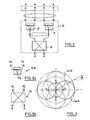
- FIG. 1a is a perspective view of a direction-finding antenna system according to the invention using symmetrical dipoles as radiating elements.
- Figure 1b is a schematic top view of the antenna system of Figure 1a.
- FIG. 2 is the diagram of a processing unit of the antenna system according to the invention.
- FIG. 3a represents a suitable power divider by two used in the processing unit of FIG. 2.
- FIG. 3b represents a hybrid junction used in the processing unit of FIG. 2.
- FIG. 4 is a horizontal diagram illustrating the operation of the processing unit of FIG. 2.
- Figure 5 is a first embodiment of an antenna system according to the invention.
- Figure 6 is a second embodiment of an antenna system according to the invention.
- FIG. 7 is a goniometry curve obtained using the antenna system according to the invention.
- Figure 8 is a horizontal diagram of an antenna system according to the invention.
- FIGS. 9a and 9b are perspective and top views of an antenna system according to the invention using symmetrical dipoles with dihedral reflectors.
- FIG. 10 is a perspective view of an antenna system according to the invention using unipoles on a reflector plate.
- FIGS. 11a and 11b are perspective views of an antenna system according to the invention using unipoles with trihedral reflectors.
- the direction-finding antenna system represented in FIG. 1a comprises radiating elements constituted by four identical symmetrical dipoles denoted E, N, O, S, distributed, as shown in FIG. 1b, uniformly on a circle 6 around a central conductive mast 5.
- the diameter of the metal mast 5 has no appreciable effect on the performance of the antenna. Also, it can be more or less important (round or square) depending on the mechanical constraints. In the VHF and UHF ranges, for example, the diameter can be of the order of 150 mm, or 0.05 ⁇ to 0.2 ⁇ , ⁇ being the wavelength.
- the total height of the mast 5 carrying half the height of the network of the four dipoles must be greater than the length of the radiating elements. Typically, this length is 0.7 ⁇ or more, or 2.10 m at 100 MHz for example.
- the diameter of the circular array is an essential parameter in the design of the antenna. It must be less than the wavelength for an operation compatible with the principle of goniometry used.
- this diameter is less than 0.75 ⁇ and, preferably, it is between 0.2 ⁇ and 0.6 ⁇ . It is chosen according to the radiating elements and the working frequency band.
- the antenna system of FIGS. 1a and 1b is intended to determine the angle of incidence ⁇ (see FIG. 1b) of the direction of propagation of a plane electromagnetic wave with a reference direction, for example the axis O-E.
- the antenna system object of the invention, comprises a unit 10 for processing the signals supplied by the four dipoles E, N, O, S.
- This processing unit associated with the antenna may have the form of a circuit enclosed in a small metal case with connectors, arranged either at the height of the radiating elements and inside the mast 5, or at the base of the mast.
- the length of the cables connecting each dipole to said processing unit must be identical.
- the processing unit 10 comprises a first 11 power divider by two matched receiving the signals supplied by the first EO pair of dipoles and a second 12 power divider by two matched, identical to the first, receiving the signals provided by the second NS pair of dipoles.
- the two lines connecting the two power dividers to the hybrid junction are of equal electrical length.
- the term adapted power divider by two comes from the fact that this type of device, used in emission, provides at output at two identical loads perfectly balanced powers and that in addition the two outputs are radioelectrically decoupled one with respect to the other so that the device is also a signal summator in reception mode.
- the adapted power divider 11, 12 by two shown in FIG. 3a operates as follows: if a1 and a2 are the signals incoming, the output signal is given, in the usual complex notation, by: where ⁇ o is an arbitrary phase fixed by the technology of realization of the divider.
- the 3dB-90 ° hybrid junction shown in Figure 3b also called the 3dB coupler, provides two output signals in response to the two input signals a1 ′ and a2 ′, namely, at output A: and on exit B: ⁇ 1 being another arbitrary phase fixed by the technology of realization of the 3dB coupler.
- the diagram in Figure 4 illustrates on the plan horizontal the directional responses of each pair of dipoles to a plane electromagnetic wave of incidence ⁇ .
- the circles in dotted lines correspond to the sin en signal from the pair NS, and the circles in solid lines are associated with the signal in cos ⁇ supplied by the pair EO.
- the antenna system according to the invention thus provides a means of obtaining two signals whose phase difference is linear with respect to the angle of incidence ⁇ sought.
- the system is completely omni-directional.
- the goniometry curve ⁇ ( ⁇ ) is given in FIG. 7 by way of example.
- This phase non-linearity error ⁇ is a periodic function of ⁇ , with a period of 90 ° and an amplitude of approximately 4 ° for the example considered.
- FIG. 8 shows the horizontal diagram at zero site of each of the outputs A and B of the processing unit 10.
- the diagram is omnidirectional to within ⁇ 0.3 dB, and it is identical for the two outputs A and B. It was obtained with an antenna operating in the VHF range with a diameter close to 0.28 ⁇ and comprising four dipoles half-wave around a mast 0.15 m in diameter. The result illustrated in Figure 7 corresponds to this dimensional configuration.
- the antenna system according to the invention is not sensitive to the horizontal polarization of the incident wave, which would otherwise, if it is high, deform the line of goniometry.
- the polarization discrimination of the antenna is greater than 25 dB for a careful design of the antenna.
- the location accuracy in azimuth is not very sensitive to the site angle of the incident wave. Good accuracy is maintained at high sites and is in fact limited only by the loss of sensitivity linked to the attenuation of the signal received at high sites, attenuation varying as the square of the sine of the angle d 'elevation.
- the components of the processing unit 10 can be based on ferrite material in the HF, VHF or even UHF ranges for reasons of compactness, or based on microstrip technology in the highest frequency ranges.
- FIG. 5 shows, following the processing unit 10, a circuit 20 for receiving signals of the same amplitude delivered on the terminals A and B by the processing unit 10.
- the two signals leaving the receiver circuit 20 at the terminals A1 and B1 are then processed by a sine-cosine resolver 30 allowing, thanks to two dividers 34, a phase shifter 31 and two identical coherent detectors 32 followed by two integrators 33 of have two continuous proportional signals at Atec and B2, one at the cosine and the other at the sine of the phase shift angle between the signals from the antenna.
- the two output signals from resolver 30 are applied to the plates of a cathode ray tube to display directly and in real time the angle of incidence ⁇ (modulo ⁇ ) by means of a calibration of the complete system.
- the second embodiment illustrated in FIG. 6 is based on digital processing of the signals coming from the resolver 30 by a direction finding processor 40 comprising two analog-digital converters 41 which apply the signals thus digitized to a computer 42 in order to determine their phase shift.
- the value of this phase shift is compared by a digital comparator 43 to the standard goniometry curve of the complete system, previously stored in a non-volatile memory 44. This comparison provides the exact angle ⁇ (modulo ⁇ ) whose value is displayed on a display 45.
- display designates any device for displaying the quantity ⁇ , including a graphic unit.
- FIGS. 9a and 9b show radiating elements constituted by symmetrical dipoles E, N, O, S separated by reflectors 50 forming rectangular dihedrons.
- This type of antenna is preferably used for ground applications in the UHF range.
- the length of the link arms between the dipoles and the mast 5 varies between 0.2 ⁇ and 0.3 ⁇ .
- the length of the separators 50 must not be too large to ensure omnidirectionality; it is typically chosen between 0.4 ⁇ and 0.5 ⁇ .
- the height of the separators 50 it must be greater than that of the dipoles, ie 0.6 ⁇ to 0.7 ⁇ .
- the antenna of FIG. 10 is composed of radiating elements in the form of quarter-wave unipoles arranged on a reflective plate 60 around the central mast 5 according to a circle having, as for the dipoles of FIG. 1a, a diameter from 0.2 ⁇ to 0.6 ⁇ .
- This antenna is intended to be installed mainly on an aircraft. Its typical working frequency is in the L band.
- FIGS. 11a and 11b show an antenna according to the invention formed by four unipoles placed inside trihedral triangles 70. All the faces of the trihedra are identical squares with a side of approximately 0.4 ⁇ . This type of antenna is used for applications on the ground or on a vehicle, in the UHF and VHF ranges.
- the antenna system described can operate in a completely equivalent manner in transmission in order to produce electromagnetic waves having amplitude and phase properties equivalent to operation at reception in a given direction ⁇ .
Applications Claiming Priority (2)
| Application Number | Priority Date | Filing Date | Title |
|---|---|---|---|
| FR9005386A FR2661561B1 (fr) | 1990-04-27 | 1990-04-27 | Systeme d'antenne de radiogoniometrie a couverture omnidirectionnelle. |
| FR9005386 | 1990-04-27 |
Publications (2)
| Publication Number | Publication Date |
|---|---|
| EP0454582A1 true EP0454582A1 (de) | 1991-10-30 |
| EP0454582B1 EP0454582B1 (de) | 1994-12-28 |
Family
ID=9396156
Family Applications (1)
| Application Number | Title | Priority Date | Filing Date |
|---|---|---|---|
| EP91401099A Expired - Lifetime EP0454582B1 (de) | 1990-04-27 | 1991-04-25 | Rundstrahl-Funkpeilantennensystem |
Country Status (4)
| Country | Link |
|---|---|
| US (1) | US5237336A (de) |
| EP (1) | EP0454582B1 (de) |
| DE (1) | DE69106206T2 (de) |
| FR (1) | FR2661561B1 (de) |
Cited By (3)
| Publication number | Priority date | Publication date | Assignee | Title |
|---|---|---|---|---|
| US5264862A (en) * | 1991-12-10 | 1993-11-23 | Hazeltine Corp. | High-isolation collocated antenna systems |
| WO2008047158A1 (en) * | 2006-10-16 | 2008-04-24 | Roke Manor Research Limited | Radio wave detection apparatus |
| CN113296051A (zh) * | 2021-05-31 | 2021-08-24 | 中国电子科技集团公司第二十九研究所 | 一种天线二维分区测向的方法、设备及存储介质 |
Families Citing this family (12)
| Publication number | Priority date | Publication date | Assignee | Title |
|---|---|---|---|---|
| US5872547A (en) * | 1996-07-16 | 1999-02-16 | Metawave Communications Corporation | Conical omni-directional coverage multibeam antenna with parasitic elements |
| US5940048A (en) | 1996-07-16 | 1999-08-17 | Metawave Communications Corporation | Conical omni-directional coverage multibeam antenna |
| US6480168B1 (en) | 2000-09-19 | 2002-11-12 | Lockheed Martin Corporation | Compact multi-band direction-finding antenna system |
| ATE371198T1 (de) * | 2002-05-29 | 2007-09-15 | Lior Baussi | Zellulares telefon zur richtungsbestimmung |
| US7271826B2 (en) * | 2002-07-03 | 2007-09-18 | Lufthansa Technik Ag | Communications installation for aircraft |
| US6768473B2 (en) * | 2002-07-15 | 2004-07-27 | Spx Corporation | Antenna system and method |
| US8138986B2 (en) * | 2008-12-10 | 2012-03-20 | Sensis Corporation | Dipole array with reflector and integrated electronics |
| CN104769774B (zh) * | 2012-04-04 | 2018-03-09 | Hrl实验室有限责任公司 | 宽带电抗减少的天线阵列 |
| CN102834972B (zh) * | 2012-04-20 | 2015-05-27 | 华为技术有限公司 | 天线及基站 |
| US9293804B2 (en) * | 2013-03-25 | 2016-03-22 | Dbspectra, Inc. | Integrated antenna system for a train control system |
| EP3285083B1 (de) * | 2016-08-19 | 2019-06-12 | Rohde & Schwarz GmbH & Co. KG | Verfahren zur peilung und peilungsantenneneinheit |
| JP7285421B2 (ja) * | 2021-03-29 | 2023-06-02 | 日本電気株式会社 | アンテナ装置 |
Citations (6)
| Publication number | Priority date | Publication date | Assignee | Title |
|---|---|---|---|---|
| US2720648A (en) * | 1952-06-11 | 1955-10-11 | Electroport Systems Inc | Direction finding systems and receiving channels |
| US2953782A (en) * | 1955-05-04 | 1960-09-20 | Marconi Wireless Telegraph Co | Receiving aerial systems |
| FR2163332A1 (de) * | 1971-12-14 | 1973-07-27 | Onera (Off Nat Aerospatiale) | |
| DE2525486A1 (de) * | 1975-06-07 | 1976-12-23 | Licentia Gmbh | Peileinrichtung mit zweikanal- watson-watt-empfaenger |
| US4528567A (en) * | 1981-08-10 | 1985-07-09 | Argo Systems, Inc. | Radio signal receiving system |
| US4636796A (en) * | 1984-06-15 | 1987-01-13 | General Research Of Electronics, Inc. | Radio direction finding system |
Family Cites Families (7)
| Publication number | Priority date | Publication date | Assignee | Title |
|---|---|---|---|---|
| US2581444A (en) * | 1949-09-28 | 1952-01-08 | Standard Telephones Cables Ltd | Direction finder |
| US4207572A (en) * | 1977-10-25 | 1980-06-10 | Southwest Research Institute | Sky wave DF antenna system |
| GB2154803B (en) * | 1984-07-23 | 1988-08-17 | C S Antennas Ltd | Antenna system |
| US4658262A (en) * | 1985-02-19 | 1987-04-14 | Duhamel Raymond H | Dual polarized sinuous antennas |
| US4870420A (en) * | 1985-06-24 | 1989-09-26 | Sanders Associates, Inc. | Signal acquisition apparatus and method |
| US4814777A (en) * | 1987-07-31 | 1989-03-21 | Raytheon Company | Dual-polarization, omni-directional antenna system |
| US4983988A (en) * | 1988-11-21 | 1991-01-08 | E-Systems, Inc. | Antenna with enhanced gain |
-
1990
- 1990-04-27 FR FR9005386A patent/FR2661561B1/fr not_active Expired - Fee Related
-
1991
- 1991-04-25 EP EP91401099A patent/EP0454582B1/de not_active Expired - Lifetime
- 1991-04-25 DE DE69106206T patent/DE69106206T2/de not_active Expired - Fee Related
- 1991-04-26 US US07/692,179 patent/US5237336A/en not_active Expired - Fee Related
Patent Citations (6)
| Publication number | Priority date | Publication date | Assignee | Title |
|---|---|---|---|---|
| US2720648A (en) * | 1952-06-11 | 1955-10-11 | Electroport Systems Inc | Direction finding systems and receiving channels |
| US2953782A (en) * | 1955-05-04 | 1960-09-20 | Marconi Wireless Telegraph Co | Receiving aerial systems |
| FR2163332A1 (de) * | 1971-12-14 | 1973-07-27 | Onera (Off Nat Aerospatiale) | |
| DE2525486A1 (de) * | 1975-06-07 | 1976-12-23 | Licentia Gmbh | Peileinrichtung mit zweikanal- watson-watt-empfaenger |
| US4528567A (en) * | 1981-08-10 | 1985-07-09 | Argo Systems, Inc. | Radio signal receiving system |
| US4636796A (en) * | 1984-06-15 | 1987-01-13 | General Research Of Electronics, Inc. | Radio direction finding system |
Non-Patent Citations (1)
| Title |
|---|
| IEEE TRANSACTIONS ON ANTENNAS AND PROPAGATION, vol. AP-31, no. 3, mai 1983, pages 451-455, IEEE, New York, US; H.M. ELKAMCHOUCHI: "Cylindrical and three-dimensional corner reflector antennas" * |
Cited By (4)
| Publication number | Priority date | Publication date | Assignee | Title |
|---|---|---|---|---|
| US5264862A (en) * | 1991-12-10 | 1993-11-23 | Hazeltine Corp. | High-isolation collocated antenna systems |
| WO2008047158A1 (en) * | 2006-10-16 | 2008-04-24 | Roke Manor Research Limited | Radio wave detection apparatus |
| CN113296051A (zh) * | 2021-05-31 | 2021-08-24 | 中国电子科技集团公司第二十九研究所 | 一种天线二维分区测向的方法、设备及存储介质 |
| CN113296051B (zh) * | 2021-05-31 | 2022-07-15 | 中国电子科技集团公司第二十九研究所 | 一种天线二维分区测向的方法、设备及存储介质 |
Also Published As
| Publication number | Publication date |
|---|---|
| DE69106206D1 (de) | 1995-02-09 |
| EP0454582B1 (de) | 1994-12-28 |
| DE69106206T2 (de) | 1995-08-10 |
| FR2661561B1 (fr) | 1993-02-05 |
| FR2661561A1 (fr) | 1991-10-31 |
| US5237336A (en) | 1993-08-17 |
Similar Documents
| Publication | Publication Date | Title |
|---|---|---|
| EP0454582B1 (de) | Rundstrahl-Funkpeilantennensystem | |
| EP3315994B1 (de) | Mehrstrahliger fmcw-radar, insbesondere für kraftfahrzeug | |
| EP0012055B1 (de) | In Streifenleitertechnik ausgeführter Monopulsprimärstrahler und Antenne mit einem solchen Strahler | |
| EP2762912B1 (de) | Vorrichtung und Verfahren zur Datenerfassung für die Lokalisierung einer Störquelle | |
| FR2709603A1 (fr) | Perfectionnements aux dispositifs sensibles aux rayonnements électromagnétiques. | |
| EP2217944B1 (de) | Einrichtung zum detektieren von objekten, insbesondere gefährlichen objekten | |
| FR2648570A1 (fr) | Dispositif et procede pour mesurer l'azimut et le site d'un objet | |
| EP2435847B1 (de) | Verfahren und system zum bestimmen der einfallsrichtung einer beliebige polarisation aufweisenden elektromagnetischen welle | |
| BE1012743A4 (fr) | Recepteur interferometrique de signaux electromagnetiques. | |
| FR2938925A1 (fr) | Dispositif de radar pour la surveillance maritime | |
| EP0707357A1 (de) | Antennensystem mit mehreren Speisesystemen, integriert in einem rauscharmen Umsetzer (LNC) | |
| FR2925771A1 (fr) | Reseau d'antennes directives multi polarisations large bande | |
| EP1227333B1 (de) | Verfahren und Gerät zur Positionsbestimmung eines erdgebundenen Senders mittels eines Satelliten | |
| EP3182512B1 (de) | Multizugangsantenne | |
| US9322911B1 (en) | Passive phased array imager using sub-phase sampling CMOS detectors and a smart ROIC | |
| EP3859882B1 (de) | Funksystem mit mehreren antennennetzwerken und adaptiven wellenformen | |
| EP3555653A1 (de) | Verfahren zur herstellung einer peilgruppenantenne und nach solch einem verfahren hergestellte gruppenantenne | |
| EP3667357B1 (de) | Verfahren zur störung der von einem radar gesendeten elektronischen signatur, und entsprechend angepasste sende-/empfangsvorrichtung für die umsetzung dieses verfahrens | |
| EP3900113B1 (de) | Elementare mikrostreifenantenne und gruppenantenne | |
| EP3321711A1 (de) | Aufnahmevorrichtung für antenne mit elektronischer strahlschwenkung, die im resm- und radarmodus arbeiten kann, und mit dieser vorrichtung ausgestatteter radar | |
| FR3027460A1 (fr) | Systeme antennaire compact pour la goniometrie en diversite de la polarisation | |
| EP0762534B1 (de) | Verfahren zur Verbreiterung des Strahlungsdiagramms einer Gruppenantenne mit verteilten Elementen in einem Volumen | |
| EP2822198A1 (de) | Verfahren und Vorrichtung zur Messung der Gruppenlaufzeit einer Antenne | |
| EP3534172A1 (de) | Ortungssystem, flugzeug und ortungsverfahren | |
| FR2750209A1 (fr) | Polarimetre de phase et polarigoniometre comportant un tel polarimetre |
Legal Events
| Date | Code | Title | Description |
|---|---|---|---|
| PUAI | Public reference made under article 153(3) epc to a published international application that has entered the european phase |
Free format text: ORIGINAL CODE: 0009012 |
|
| AK | Designated contracting states |
Kind code of ref document: A1 Designated state(s): DE FR GB |
|
| 17P | Request for examination filed |
Effective date: 19920330 |
|
| 17Q | First examination report despatched |
Effective date: 19940225 |
|
| GRAA | (expected) grant |
Free format text: ORIGINAL CODE: 0009210 |
|
| AK | Designated contracting states |
Kind code of ref document: B1 Designated state(s): DE FR GB |
|
| REF | Corresponds to: |
Ref document number: 69106206 Country of ref document: DE Date of ref document: 19950209 |
|
| GBT | Gb: translation of ep patent filed (gb section 77(6)(a)/1977) |
Effective date: 19950113 |
|
| PLBE | No opposition filed within time limit |
Free format text: ORIGINAL CODE: 0009261 |
|
| STAA | Information on the status of an ep patent application or granted ep patent |
Free format text: STATUS: NO OPPOSITION FILED WITHIN TIME LIMIT |
|
| 26N | No opposition filed | ||
| PGFP | Annual fee paid to national office [announced via postgrant information from national office to epo] |
Ref country code: FR Payment date: 19990429 Year of fee payment: 9 |
|
| REG | Reference to a national code |
Ref country code: FR Ref legal event code: TP |
|
| PGFP | Annual fee paid to national office [announced via postgrant information from national office to epo] |
Ref country code: GB Payment date: 20000418 Year of fee payment: 10 |
|
| PGFP | Annual fee paid to national office [announced via postgrant information from national office to epo] |
Ref country code: DE Payment date: 20000512 Year of fee payment: 10 |
|
| PG25 | Lapsed in a contracting state [announced via postgrant information from national office to epo] |
Ref country code: FR Free format text: LAPSE BECAUSE OF NON-PAYMENT OF DUE FEES Effective date: 20001229 |
|
| REG | Reference to a national code |
Ref country code: FR Ref legal event code: ST |
|
| PG25 | Lapsed in a contracting state [announced via postgrant information from national office to epo] |
Ref country code: GB Free format text: LAPSE BECAUSE OF NON-PAYMENT OF DUE FEES Effective date: 20010425 |
|
| GBPC | Gb: european patent ceased through non-payment of renewal fee |
Effective date: 20010425 |
|
| PG25 | Lapsed in a contracting state [announced via postgrant information from national office to epo] |
Ref country code: DE Free format text: LAPSE BECAUSE OF NON-PAYMENT OF DUE FEES Effective date: 20020201 |