EP0454582A1 - Radio direction finder antenna system with omnidirectional coverage - Google Patents
Radio direction finder antenna system with omnidirectional coverage Download PDFInfo
- Publication number
- EP0454582A1 EP0454582A1 EP91401099A EP91401099A EP0454582A1 EP 0454582 A1 EP0454582 A1 EP 0454582A1 EP 91401099 A EP91401099 A EP 91401099A EP 91401099 A EP91401099 A EP 91401099A EP 0454582 A1 EP0454582 A1 EP 0454582A1
- Authority
- EP
- European Patent Office
- Prior art keywords
- antenna system
- signals
- radiating elements
- dipoles
- pair
- Prior art date
- Legal status (The legal status is an assumption and is not a legal conclusion. Google has not performed a legal analysis and makes no representation as to the accuracy of the status listed.)
- Granted
Links
Images


Classifications
-
- H—ELECTRICITY
- H01—ELECTRIC ELEMENTS
- H01Q—ANTENNAS, i.e. RADIO AERIALS
- H01Q21/00—Antenna arrays or systems
- H01Q21/06—Arrays of individually energised antenna units similarly polarised and spaced apart
- H01Q21/08—Arrays of individually energised antenna units similarly polarised and spaced apart the units being spaced along or adjacent to a rectilinear path
- H01Q21/12—Parallel arrangements of substantially straight elongated conductive units
- H01Q21/14—Adcock antennas
-
- G—PHYSICS
- G01—MEASURING; TESTING
- G01S—RADIO DIRECTION-FINDING; RADIO NAVIGATION; DETERMINING DISTANCE OR VELOCITY BY USE OF RADIO WAVES; LOCATING OR PRESENCE-DETECTING BY USE OF THE REFLECTION OR RERADIATION OF RADIO WAVES; ANALOGOUS ARRANGEMENTS USING OTHER WAVES
- G01S3/00—Direction-finders for determining the direction from which infrasonic, sonic, ultrasonic, or electromagnetic waves, or particle emission, not having a directional significance, are being received
- G01S3/02—Direction-finders for determining the direction from which infrasonic, sonic, ultrasonic, or electromagnetic waves, or particle emission, not having a directional significance, are being received using radio waves
- G01S3/14—Systems for determining direction or deviation from predetermined direction
- G01S3/143—Systems for determining direction or deviation from predetermined direction by vectorial combination of signals derived from differently oriented antennae
Definitions
- the present invention relates to a direction-finding antenna system comprising four identical radiating elements distributed uniformly on a circle around a conductive mast, and intended to determine the angle of incidence of the direction of propagation of a plane electromagnetic wave with a reference direction.
- the invention finds an advantageous application in the field of radiolocation in all the radiofrequency ranges, and, in particular, in the HF, VHF and UHF ranges.
- the antenna system of the invention applies to detection and surveillance and, in particular, to anti-collision devices, between aircraft for example, and to alert. It can be installed fixed on the ground or carried by a land mobile, a ship or an aircraft.
- Direction finding applied to radiolocation is conventionally based on two known techniques, the Watson-Watt technique with Adcock antenna and the so-called Doppler technique.
- the first of these techniques uses amplitude information, in the sense that the ratio of the amplitudes of the signals from two orthogonal pairs of dipoles provides approximately the tangent of the angle of incidence sought. This method is not very precise because of the octantal error, an error sensitive moreover to the angle of elevation of the incident wave.
- the Doppler effect technique which requires a large number of radiating elements (16 or 32 for example, or even more), has a low sensitivity due to the coupling between the radiating elements and above all requires rapid cyclic switching of the radiating elements.
- the acquisition and processing electronics which is relatively complex, must be precise and stable over time.
- this technique requires an auxiliary reference antenna in order in particular to eliminate the phase modulation often present in the signals to be located.
- the technical problem to be solved by the object of the present invention is to provide an antenna system in accordance with the preamble which would not include a switching device, would offer good sensitivity and good localization accuracy, and would be compact. .
- the solution to the technical problem posed consists, according to the present invention, in that said radiating elements are associated in a first and a second pair of two radiating elements opposite and inverted with respect to each other, and in that said antenna system comprises a processing unit comprising, on the one hand, a first adapted power divider by two receiving the signals supplied by the first pair of radiating elements and a second adapted power divider by two, identical to the first, receiving the signals supplied by the second pair of radiating elements, and, on the other hand, a hybrid junction of the 3dB-90 ° type receiving the signals delivered by said power dividers by two adapters, and providing at output two signals whose phase difference is given by 2 ⁇ - ⁇ / 2 to within a constant.
- the antenna receiver is based on the following operating principle. If ⁇ is the desired angle of incidence taken with respect to a reference axis, for example the straight line joining the two radiating elements of the same pair, the signals coming from the two power dividers by two adapted are one proportional to sin ⁇ and the other to cos ⁇ . These two signals, which have the same frequency, are then processed by the 3dB-90 ° hybrid junction to give two new signals, of the same amplitude and of the same frequency, but one of which is phase shifted by ⁇ and the other by - ⁇ (to within a constant) compared to an arbitrary common reference phase. Consequently, the phase difference of the two signals varies linearly with ⁇ and is substantially equal to 2 ⁇ . A deviation of 1 degree on the angle ⁇ therefore results in a deviation of 2 degrees on the differential phase. Conversely, an uncertainty of 1 degree for example on the measurement of the differential phase of the two signals results in 0.5 degree of uncertainty on the location of the direction of propagation.
- the direction-finding antenna system works in real time, which allows the localization of signals of short duration provided that the reception chain is adapted to these pulses.
- This advantage is due to the fact that it is not necessary to switch either the radiating elements or the reception channels to extract the desired angular information.
- Another advantage of the system according to the invention is that it allows the location of an electromagnetic wave modulated in amplitude and / or in phase without using auxiliary antennas. This advantage comes from the fact that the system of the invention has at all times two signals which have the same amplitude and whose phase difference is independent of the phase modulation of the incident wave.
- the antenna system according to the invention is simple and robust, this being linked to the few mechanical parts and to the small number of components (dividers, hybrid junction) necessary for its manufacture. Its robustness results from the absence of active components (switches for example) and from the fact that no moving mechanical part is used.
- the aerial system according to the invention although of modest size compared to the wavelength, gives good localization accuracy (apart from the effect of interference linked to the environment). This advantage results in a location uncertainty typically equal to half of the instrumental uncertainty.
- Another advantage of the antenna system according to the invention is that it has a sensitivity equivalent to that which would be obtained with a single radiating element on reception, radiating element of the same type as those making up the circular array itself.
- This advantage comes from the fact that the diagram is omnidirectional and that the gain of the antenna is of the order or greater than that of a single isolated radiating element.
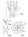
- FIG. 1a is a perspective view of a direction-finding antenna system according to the invention using symmetrical dipoles as radiating elements.
- Figure 1b is a schematic top view of the antenna system of Figure 1a.
- FIG. 2 is the diagram of a processing unit of the antenna system according to the invention.
- FIG. 3a represents a suitable power divider by two used in the processing unit of FIG. 2.
- FIG. 3b represents a hybrid junction used in the processing unit of FIG. 2.
- FIG. 4 is a horizontal diagram illustrating the operation of the processing unit of FIG. 2.
- Figure 5 is a first embodiment of an antenna system according to the invention.
- Figure 6 is a second embodiment of an antenna system according to the invention.
- FIG. 7 is a goniometry curve obtained using the antenna system according to the invention.
- Figure 8 is a horizontal diagram of an antenna system according to the invention.
- FIGS. 9a and 9b are perspective and top views of an antenna system according to the invention using symmetrical dipoles with dihedral reflectors.
- FIG. 10 is a perspective view of an antenna system according to the invention using unipoles on a reflector plate.
- FIGS. 11a and 11b are perspective views of an antenna system according to the invention using unipoles with trihedral reflectors.
- the direction-finding antenna system represented in FIG. 1a comprises radiating elements constituted by four identical symmetrical dipoles denoted E, N, O, S, distributed, as shown in FIG. 1b, uniformly on a circle 6 around a central conductive mast 5.
- the diameter of the metal mast 5 has no appreciable effect on the performance of the antenna. Also, it can be more or less important (round or square) depending on the mechanical constraints. In the VHF and UHF ranges, for example, the diameter can be of the order of 150 mm, or 0.05 ⁇ to 0.2 ⁇ , ⁇ being the wavelength.
- the total height of the mast 5 carrying half the height of the network of the four dipoles must be greater than the length of the radiating elements. Typically, this length is 0.7 ⁇ or more, or 2.10 m at 100 MHz for example.
- the diameter of the circular array is an essential parameter in the design of the antenna. It must be less than the wavelength for an operation compatible with the principle of goniometry used.
- this diameter is less than 0.75 ⁇ and, preferably, it is between 0.2 ⁇ and 0.6 ⁇ . It is chosen according to the radiating elements and the working frequency band.
- the antenna system of FIGS. 1a and 1b is intended to determine the angle of incidence ⁇ (see FIG. 1b) of the direction of propagation of a plane electromagnetic wave with a reference direction, for example the axis O-E.
- the antenna system object of the invention, comprises a unit 10 for processing the signals supplied by the four dipoles E, N, O, S.
- This processing unit associated with the antenna may have the form of a circuit enclosed in a small metal case with connectors, arranged either at the height of the radiating elements and inside the mast 5, or at the base of the mast.
- the length of the cables connecting each dipole to said processing unit must be identical.
- the processing unit 10 comprises a first 11 power divider by two matched receiving the signals supplied by the first EO pair of dipoles and a second 12 power divider by two matched, identical to the first, receiving the signals provided by the second NS pair of dipoles.
- the two lines connecting the two power dividers to the hybrid junction are of equal electrical length.
- the term adapted power divider by two comes from the fact that this type of device, used in emission, provides at output at two identical loads perfectly balanced powers and that in addition the two outputs are radioelectrically decoupled one with respect to the other so that the device is also a signal summator in reception mode.
- the adapted power divider 11, 12 by two shown in FIG. 3a operates as follows: if a1 and a2 are the signals incoming, the output signal is given, in the usual complex notation, by: where ⁇ o is an arbitrary phase fixed by the technology of realization of the divider.
- the 3dB-90 ° hybrid junction shown in Figure 3b also called the 3dB coupler, provides two output signals in response to the two input signals a1 ′ and a2 ′, namely, at output A: and on exit B: ⁇ 1 being another arbitrary phase fixed by the technology of realization of the 3dB coupler.
- the diagram in Figure 4 illustrates on the plan horizontal the directional responses of each pair of dipoles to a plane electromagnetic wave of incidence ⁇ .
- the circles in dotted lines correspond to the sin en signal from the pair NS, and the circles in solid lines are associated with the signal in cos ⁇ supplied by the pair EO.
- the antenna system according to the invention thus provides a means of obtaining two signals whose phase difference is linear with respect to the angle of incidence ⁇ sought.
- the system is completely omni-directional.
- the goniometry curve ⁇ ( ⁇ ) is given in FIG. 7 by way of example.
- This phase non-linearity error ⁇ is a periodic function of ⁇ , with a period of 90 ° and an amplitude of approximately 4 ° for the example considered.
- FIG. 8 shows the horizontal diagram at zero site of each of the outputs A and B of the processing unit 10.
- the diagram is omnidirectional to within ⁇ 0.3 dB, and it is identical for the two outputs A and B. It was obtained with an antenna operating in the VHF range with a diameter close to 0.28 ⁇ and comprising four dipoles half-wave around a mast 0.15 m in diameter. The result illustrated in Figure 7 corresponds to this dimensional configuration.
- the antenna system according to the invention is not sensitive to the horizontal polarization of the incident wave, which would otherwise, if it is high, deform the line of goniometry.
- the polarization discrimination of the antenna is greater than 25 dB for a careful design of the antenna.
- the location accuracy in azimuth is not very sensitive to the site angle of the incident wave. Good accuracy is maintained at high sites and is in fact limited only by the loss of sensitivity linked to the attenuation of the signal received at high sites, attenuation varying as the square of the sine of the angle d 'elevation.
- the components of the processing unit 10 can be based on ferrite material in the HF, VHF or even UHF ranges for reasons of compactness, or based on microstrip technology in the highest frequency ranges.
- FIG. 5 shows, following the processing unit 10, a circuit 20 for receiving signals of the same amplitude delivered on the terminals A and B by the processing unit 10.
- the two signals leaving the receiver circuit 20 at the terminals A1 and B1 are then processed by a sine-cosine resolver 30 allowing, thanks to two dividers 34, a phase shifter 31 and two identical coherent detectors 32 followed by two integrators 33 of have two continuous proportional signals at Atec and B2, one at the cosine and the other at the sine of the phase shift angle between the signals from the antenna.
- the two output signals from resolver 30 are applied to the plates of a cathode ray tube to display directly and in real time the angle of incidence ⁇ (modulo ⁇ ) by means of a calibration of the complete system.
- the second embodiment illustrated in FIG. 6 is based on digital processing of the signals coming from the resolver 30 by a direction finding processor 40 comprising two analog-digital converters 41 which apply the signals thus digitized to a computer 42 in order to determine their phase shift.
- the value of this phase shift is compared by a digital comparator 43 to the standard goniometry curve of the complete system, previously stored in a non-volatile memory 44. This comparison provides the exact angle ⁇ (modulo ⁇ ) whose value is displayed on a display 45.
- display designates any device for displaying the quantity ⁇ , including a graphic unit.
- FIGS. 9a and 9b show radiating elements constituted by symmetrical dipoles E, N, O, S separated by reflectors 50 forming rectangular dihedrons.
- This type of antenna is preferably used for ground applications in the UHF range.
- the length of the link arms between the dipoles and the mast 5 varies between 0.2 ⁇ and 0.3 ⁇ .
- the length of the separators 50 must not be too large to ensure omnidirectionality; it is typically chosen between 0.4 ⁇ and 0.5 ⁇ .
- the height of the separators 50 it must be greater than that of the dipoles, ie 0.6 ⁇ to 0.7 ⁇ .
- the antenna of FIG. 10 is composed of radiating elements in the form of quarter-wave unipoles arranged on a reflective plate 60 around the central mast 5 according to a circle having, as for the dipoles of FIG. 1a, a diameter from 0.2 ⁇ to 0.6 ⁇ .
- This antenna is intended to be installed mainly on an aircraft. Its typical working frequency is in the L band.
- FIGS. 11a and 11b show an antenna according to the invention formed by four unipoles placed inside trihedral triangles 70. All the faces of the trihedra are identical squares with a side of approximately 0.4 ⁇ . This type of antenna is used for applications on the ground or on a vehicle, in the UHF and VHF ranges.
- the antenna system described can operate in a completely equivalent manner in transmission in order to produce electromagnetic waves having amplitude and phase properties equivalent to operation at reception in a given direction ⁇ .
Abstract
Description
La présente invention concerne un système d'antenne de radiogoniométrie comportant quatre éléments rayonnants identiques répartis uniformément sur un cercle autour d'un mât conducteur, et destiné à déterminer l'angle d'incidence de la direction de propagation d'une onde électromagnétique plane avec une direction de référence.The present invention relates to a direction-finding antenna system comprising four identical radiating elements distributed uniformly on a circle around a conductive mast, and intended to determine the angle of incidence of the direction of propagation of a plane electromagnetic wave with a reference direction.
L'invention trouve une application avantageuse dans le domaine de la radiolocalisation dans toutes les gammes de radiofréquence, et, en particulier, dans les gammes HF, VHF et UHF. D'une manière générale, le système d'antenne de l'invention s'applique à la détection et à la surveillance et, en particulier, aux dispositifs anti-collision, entre avions par exemple, et d'alerte. Il peut être installé fixe au sol ou porté par un mobile terreste, un navire ou un aéronef.The invention finds an advantageous application in the field of radiolocation in all the radiofrequency ranges, and, in particular, in the HF, VHF and UHF ranges. In general, the antenna system of the invention applies to detection and surveillance and, in particular, to anti-collision devices, between aircraft for example, and to alert. It can be installed fixed on the ground or carried by a land mobile, a ship or an aircraft.
La radiogoniométrie appliquée à la radiolocalisation repose classiquement sur deux techniques connues, la technique de Watson-Watt avec antenne Adcock et la technique dite à effet Doppler.Direction finding applied to radiolocation is conventionally based on two known techniques, the Watson-Watt technique with Adcock antenna and the so-called Doppler technique.
La première de ces techniques exploite l'information d'amplitude, en ce sens que le rapport des amplitudes des signaux issus de deux paires orthogonales de dipôles fournit approximativement la tangente de l'angle d'incidence cherché. Cette méthode est peu précise en raison de l'erreur octantale, erreur sensible par ailleurs à l'angle d'élévation de l'onde incidente.The first of these techniques uses amplitude information, in the sense that the ratio of the amplitudes of the signals from two orthogonal pairs of dipoles provides approximately the tangent of the angle of incidence sought. This method is not very precise because of the octantal error, an error sensitive moreover to the angle of elevation of the incident wave.
La technique à effet Doppler, qui requiert un nombre d'élément rayonnants important (16 ou 32 par exemple, voire plus), présente une faible sensibilité du fait du couplage entre les éléments rayonnants et surtout nécessite une commutation cyclique rapide des éléments rayonnants. D'autre part, l'électronique d'acquisition et de traitement qui est relativement complexe doit être précise et stable dans le temps. En outre, cette technique nécessite une antenne auxiliaire de référence afin en particulier d'éliminer la modulation de phase souvent présente dans les signaux à localiser.The Doppler effect technique, which requires a large number of radiating elements (16 or 32 for example, or even more), has a low sensitivity due to the coupling between the radiating elements and above all requires rapid cyclic switching of the radiating elements. On the other hand, the acquisition and processing electronics, which is relatively complex, must be precise and stable over time. In addition, this technique requires an auxiliary reference antenna in order in particular to eliminate the phase modulation often present in the signals to be located.
Il existe d'autres techniques basées sur le principe connu de l'interférométrie. Mais elles requièrent dans tous les cas la commutation de plusieurs antennes.There are other techniques based on the known principle of interferometry. However, in all cases they require the switching of several antennas.
Aussi, le problème technique à résoudre par l'objet de la présente invention est de réaliser un système d'antenne conforme au préambule qui ne comporterait pas de dispositif de commutation, offrirait une bonne sensibilité et une bonne précision de localisation, et serait peu emcombrant.Also, the technical problem to be solved by the object of the present invention is to provide an antenna system in accordance with the preamble which would not include a switching device, would offer good sensitivity and good localization accuracy, and would be compact. .
La solution au problème technique posé consiste, selon la présente invention, en ce que lesdits éléments rayonnants sont associés en une première et une deuxième paires de deux éléments rayonnants opposés et inversés l'un par rapport à l'autre, et en ce que ledit système d'antenne comporte une unité de traitement comprenant, d'une part, un premier diviseur de puissance par deux adapté recevant les signaux fournis par la première paire d'éléments rayonnants et un deuxième diviseur de puissance par deux adapté, identique au premier, recevant les signaux fournis par la deuxième paire d'éléments rayonnants, et, d'autre part, une jonction hybride du type 3dB-90° recevant les signaux délivrés par lesdits diviseurs de puissance par deux adaptés, et fournissant en sortie deux signaux dont la différence de phase est donnée par 2 ϑ - π /2 à une constante près.The solution to the technical problem posed consists, according to the present invention, in that said radiating elements are associated in a first and a second pair of two radiating elements opposite and inverted with respect to each other, and in that said antenna system comprises a processing unit comprising, on the one hand, a first adapted power divider by two receiving the signals supplied by the first pair of radiating elements and a second adapted power divider by two, identical to the first, receiving the signals supplied by the second pair of radiating elements, and, on the other hand, a hybrid junction of the 3dB-90 ° type receiving the signals delivered by said power dividers by two adapters, and providing at output two signals whose phase difference is given by 2 ϑ - π / 2 to within a constant.
Comme on le verra plus en détail plus loin, le récepteur d'antenne repose sur le principe de fonctionnement suivant. Si ϑ est l'angle d'incidence recherché pris par rapport à un axe de référence, par exemple la droite joignant les deux éléments rayonnants d'une même paire, les signaux issus des deux diviseurs de puissance par deux adaptés sont l'un proportionnel à sinϑ et l'autre à cosϑ . Ces deux signaux, qui ont la même fréquence, sont ensuite traités par la jonction hybride 3dB-90° pour donner deux nouveaux signaux, de même amplitude et de même fréquence, mais dont l'un est déphasé de ϑ et l'autre de - ϑ (à une constante près) par rapport à une phase de référence commune arbitraire. Par conséquent, la différence de phase des deux signaux varie linéairement avec ϑ et vaut sensiblement 2 ϑ. Un écart de 1 degré sur l'angle ϑ se traduit donc par un écart de 2 degrés sur la phase différentielle. Inversement, une incertitude de 1 degré par exemple sur la mesure de la phase différentielle des deux signaux se traduit par 0,5 degré d'incertitude sur la localisation de la direction de propagation.As will be seen in more detail below, the antenna receiver is based on the following operating principle. If ϑ is the desired angle of incidence taken with respect to a reference axis, for example the straight line joining the two radiating elements of the same pair, the signals coming from the two power dividers by two adapted are one proportional to sinϑ and the other to cosϑ. These two signals, which have the same frequency, are then processed by the 3dB-90 ° hybrid junction to give two new signals, of the same amplitude and of the same frequency, but one of which is phase shifted by ϑ and the other by - ϑ (to within a constant) compared to an arbitrary common reference phase. Consequently, the phase difference of the two signals varies linearly with ϑ and is substantially equal to 2 ϑ. A deviation of 1 degree on the angle ϑ therefore results in a deviation of 2 degrees on the differential phase. Conversely, an uncertainty of 1 degree for example on the measurement of the differential phase of the two signals results in 0.5 degree of uncertainty on the location of the direction of propagation.
Comme on peut le constater, le système d'antenne de radiogoniométrie, objet de l'invention, travaille en temps réel, ce qui permet la localisation de signaux de courte durée pourvu que la chaîne de réception soit adaptée à ces impulsions. Cet avantage est dû au fait qu'il n'est pas nécessaire de commuter ni les éléments rayonnants ni les voies de réception pour extraire l'information angulaire désirée. Un autre avantage du système selon l'invention est de permettre la localisation d'une onde électromagnétique modulée en amplitude et/ou en phase sans faire appel à des antennes auxiliaires. Cet avantage vient de ce que le système de l'invention présente à tout instant deux signaux qui ont la même amplitude et dont la différence de phase est indépendante de la modulation de phase de l'onde incidente.As can be seen, the direction-finding antenna system, object of the invention, works in real time, which allows the localization of signals of short duration provided that the reception chain is adapted to these pulses. This advantage is due to the fact that it is not necessary to switch either the radiating elements or the reception channels to extract the desired angular information. Another advantage of the system according to the invention is that it allows the location of an electromagnetic wave modulated in amplitude and / or in phase without using auxiliary antennas. This advantage comes from the fact that the system of the invention has at all times two signals which have the same amplitude and whose phase difference is independent of the phase modulation of the incident wave.
D'autre part, le système d'antenne selon l'invention est simple et robuste, ceci étant lié au peu de pièces mécaniques et au petit nombre de composants (diviseurs, jonction hybride) nécessaire à sa fabrication. Sa robustesse découle de l'absence de composants actifs (commutateurs par exemple) et du fait qu'aucune pièce mécanique mobile n'est utilisée.On the other hand, the antenna system according to the invention is simple and robust, this being linked to the few mechanical parts and to the small number of components (dividers, hybrid junction) necessary for its manufacture. Its robustness results from the absence of active components (switches for example) and from the fact that no moving mechanical part is used.
Il faut noter, par ailleurs, que le système d'aérien conforme à l'invention, bien que de dimension modeste par rapport à la longueur d'onde, donne une bonne précision de localisation (hormis l'effet des interférences liées à l'environnement). Cet avantage se traduit par une incertitude de localisation typiquement égale à la moitié de l'incertitude instrumentale.It should also be noted that the aerial system according to the invention, although of modest size compared to the wavelength, gives good localization accuracy (apart from the effect of interference linked to the environment). This advantage results in a location uncertainty typically equal to half of the instrumental uncertainty.
Enfin, un autre avantage du système d'antenne selon l'invention est de présenter une sensibilité équivalente à celle qu'on obtiendrait avec un élément rayonnant unique en réception, élément rayonnant de même type que ceux composant le réseau circulaire lui-même. Cet avantage vient de ce que le diagramme est omnidirectionnel et que le gain de l'antenne est de l'ordre ou supérieur à celui d'un élément rayonnant unique isolé.Finally, another advantage of the antenna system according to the invention is that it has a sensitivity equivalent to that which would be obtained with a single radiating element on reception, radiating element of the same type as those making up the circular array itself. This advantage comes from the fact that the diagram is omnidirectional and that the gain of the antenna is of the order or greater than that of a single isolated radiating element.
Dans le cas d'une utilisation dans la gamme des basses fréquences, et en raison des multi-trajets, il y a intérêt à déployer plusieurs systèmes conformes à l'invention afin d'éliminer, moyennant un traitement adéquat, les ondes parasites d'interférence.In the case of use in the low frequency range, and because of the multi-paths, it is advantageous to deploy several systems in accordance with the invention in order to eliminate, with adequate treatment, the parasitic waves from interference.
La description qui va suivre en regard des dessins annexés, donnés à titre d'exemples non limitatifs, fera bien comprendre en quoi consiste l'invention et comment elle peut être réalisée.The description which follows with reference to the appended drawings, given by way of nonlimiting examples, will make it clear what the invention consists of and how it can be implemented.
La figure 1a est une vue en perspective d'un système d'antenne de radiogoniométrie selon l'invention mettant en oeuvre des dipôles symétriques comme éléments rayonnants.FIG. 1a is a perspective view of a direction-finding antenna system according to the invention using symmetrical dipoles as radiating elements.
La figure 1b est une vue schématique de dessus du système d'antenne de la figure 1a.Figure 1b is a schematic top view of the antenna system of Figure 1a.
La figure 2 est le schéma d'une unité de traitement du système d'antenne selon l'invention.FIG. 2 is the diagram of a processing unit of the antenna system according to the invention.
La figure 3a représente un diviseur de puissance par deux adapté utilisé dans l'unité de traitement de la figure 2.FIG. 3a represents a suitable power divider by two used in the processing unit of FIG. 2.
La figure 3b représente une jonction hybride utilisée dans l'unité de traitement de la figure 2.FIG. 3b represents a hybrid junction used in the processing unit of FIG. 2.
La figure 4 est un diagramme horizontal illustrant le fonctionnement de l'unité de traitement de la figure 2.FIG. 4 is a horizontal diagram illustrating the operation of the processing unit of FIG. 2.
La figure 5 est un premier schéma de réalisation d'un système d'antenne selon l'invention.Figure 5 is a first embodiment of an antenna system according to the invention.
La figure 6 est un deuxième schéma de réalisation d'un système d'antenne selon l'invention.Figure 6 is a second embodiment of an antenna system according to the invention.
La figure 7 est une courbe de goniométrie obtenue à l'aide du système d'antenne selon l'invention.FIG. 7 is a goniometry curve obtained using the antenna system according to the invention.
La figure 8 est un diagramme horizontal d'un système d'antenne selon l'invention.Figure 8 is a horizontal diagram of an antenna system according to the invention.
Les figures 9a et 9b sont des vues en perspective et de dessus d'un système d'antenne selon l'invention mettant en oeuvre des dipôles symétriques à réflecteurs dièdres.FIGS. 9a and 9b are perspective and top views of an antenna system according to the invention using symmetrical dipoles with dihedral reflectors.
La figure 10 est une vue en perspective d'un système d'antenne selon l'invention mettant en oeuvre des unipôles sur plateau réflecteur.FIG. 10 is a perspective view of an antenna system according to the invention using unipoles on a reflector plate.
Les figures 11a et 11b sont des vues en perspective d'un système d'antenne selon l'invention mettant en oeuvre des unipôles à réflecteurs trièdres.FIGS. 11a and 11b are perspective views of an antenna system according to the invention using unipoles with trihedral reflectors.
Le système d'antenne de radiogoniométrie représenté à la figure 1a comporte des éléments rayonnants constitués par quatre dipôles symétriques identiques notés E, N, O, S, répartis, ainsi que le montre la figure 1b, uniformément sur un cercle 6 autour d'un mât central conducteur 5.The direction-finding antenna system represented in FIG. 1a comprises radiating elements constituted by four identical symmetrical dipoles denoted E, N, O, S, distributed, as shown in FIG. 1b, uniformly on a
Le diamètre du mât métallique 5 n'a pas d'effet sensible sur les performances de l'antenne. Aussi, peut-il être plus ou moins important (rond ou carré) selon les contraintes mécaniques. Dans les gammes VHF et UHF, par exemple, le diamètre peut être de l'ordre de 150 mm, soit 0,05λ à 0,2 λ , λ étant la longueur d'onde.The diameter of the
La hauteur totale du mât 5 portant à mi-hauteur le réseau des quatre dipôles doit être supérieure à la longueur des éléments rayonnants. Typiquement, cette longueur est de 0,7 λ ou plus, soit 2,10 m à 100 MHz par exemple.The total height of the
Le diamètre du réseau circulaire est un paramètre essentiel de la conception de l'antenne. Il doit être inférieur à la longueur d'onde pour un fonctionnement compatible avec le principe de goniométrie utilisé. Avantageusement, ce diamètre est inférieur à 0,75 λ et, de préférence, il est compris entre 0,2 λ et 0,6 λ . Il est choisi en fonction des éléments rayonnants et de la bande de fréquence de travail.The diameter of the circular array is an essential parameter in the design of the antenna. It must be less than the wavelength for an operation compatible with the principle of goniometry used. Advantageously, this diameter is less than 0.75 λ and, preferably, it is between 0.2 λ and 0.6 λ. It is chosen according to the radiating elements and the working frequency band.
Les éléments rayonnants tels que les dipôles demi-onde classiques symétriques ou repliés (type "trombone" ou "folded"), les unipôles quart d'onde sur plateaux réflecteurs, les dipôles et unipôles à réflecteurs dièdres ou trièdres, sont des exemples non limitatifs d'éléments rayonnants possibles. Le choix de tels ou tels éléments rayonnants dépend de la gamme de fréquence, de la largeur de bande, ainsi que de l'environnement opérationnel du système d'antenne selon l'invention. Cependant, les dimensions et le type même des éléments rayonnants ne sont astreints qu'aux conditions suivantes :
- les éléments rayonnants sont de type peu directif en azimut,
- les éléments rayonnants sont à polarisation préférentielle verticale,
- les dimensions doivent être compatibles avec la mise en réseau circulaire de quatre éléments rayonnants.
- the radiating elements are of little directional type in azimuth,
- the radiating elements are with preferential vertical polarization,
- the dimensions must be compatible with the circular network of four radiating elements.
le système d'antenne des figures 1a et 1b est destiné à déterminer l'angle d'incidence ϑ (voir figure 1b) de la direction de propagation d'une onde électromagnétique plane avec une direction de référence, par exemple l'axe O-E.the antenna system of FIGS. 1a and 1b is intended to determine the angle of incidence ϑ (see FIG. 1b) of the direction of propagation of a plane electromagnetic wave with a reference direction, for example the axis O-E.
Pour que le fonctionnement soit conforme au principe de goniométrie utilisé, les deux dipôles de chaque paire sont inversés l'un par rapport à l'autre. Cette inversion qui peut être obtenue mécaniquement ou électriquement, a pour effet de créer un déphasage de 180° entre les courants circulant sur les deux dipôles d'une même paire.In order for the operation to be in accordance with the principle of goniometry used, the two dipoles of each pair are reversed with respect to each other. This inversion, which can be obtained mechanically or electrically, has the effect of creating a 180 ° phase shift between the currents flowing on the two dipoles of the same pair.
Comme le montrent les figures 1a et 1b, le système d'antenne, objet de l'invention, comporte une unité 10 de traitement des signaux fournis par les quatre dipôles E, N, O, S. Cette unité de traitement associée à l'antenne peut avoir la forme d'un circuit enfermé dans un petit boîtier métallique avec connecteurs, disposé soit à hauteur des éléments rayonnants et à l'intérieur du mât 5, soit à la base du mât. Toutefois, quelle que soit la localisation de l'unité 10 de traitement, la longueur des câbles reliant chaque dipôle à ladite unité de traitement devra être identique.As shown in FIGS. 1a and 1b, the antenna system, object of the invention, comprises a
Conformément à la figure 2, l'unité 10 de traitement comprent un premier 11 diviseur de puissance par deux adapté recevant les signaux fournis par la première paire E-O de dipôles et un deuxième 12 diviseur de puissance par deux adapté, identique au premier, recevant les signaux fournis par la deuxième paire N-S de dipôles. Les deux lignes raccordant les deux diviseurs de puissance à la jonction hybride sont d'égales longueurs électriques.In accordance with FIG. 2, the
Le terme de diviseur de puissance par deux adapté vient du fait que ce type de dispositif, utilisé en émission, fournit en sortie à deux charges identiques des puissances parfaitement équilibrées et qu'en outre les deux sorties sont radioélectriquement découplées l'une par rapport à l'autre de sorte que le dispositif est aussi un sommateur de signaux en mode réception.The term adapted power divider by two comes from the fact that this type of device, used in emission, provides at output at two identical loads perfectly balanced powers and that in addition the two outputs are radioelectrically decoupled one with respect to the other so that the device is also a signal summator in reception mode.
Le diviseur 11, 12 de puissance par deux adapté représenté sur la figure 3a fonctionne de la manière suivante : si a1 et a2 sont les signaux entrant, le signal de sortie est donné, en notation complexe habituelle, par :
où φ o est une phase arbitraire fixée par la technologie de réalisation du diviseur.The adapted
where φ o is an arbitrary phase fixed by the technology of realization of the divider.
La jonction hybride 3dB-90° montrée à la figure 3b, appelée aussi coupleur 3dB, fournit deux signaux de sortie en réponse aux deux signaux d'entrée a1′ et a2′, à savoir, sur la sortie A :
et sur la sortie B :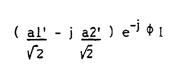
φ₁ étant une autre phase arbitraire fixée par la technologie de réalisation du coupleur 3dB.The 3dB-90 ° hybrid junction shown in Figure 3b, also called the 3dB coupler, provides two output signals in response to the two input signals a1 ′ and a2 ′, namely, at output A:
and on exit B:
φ₁ being another arbitrary phase fixed by the technology of realization of the 3dB coupler.
Dans la mesure où elles affectent tous les signaux de la même façon, les phases arbitraires φ₀ et φ₁ n'interviennent pas dans le résultat final. Aussi, dans le but de simplifier l'écriture, elles seront dans la suite prises égales à zéro.Insofar as they affect all the signals in the same way, the arbitrary phases φ₀ and φ₁ do not intervene in the final result. Also, in order to simplify the writing, they will be taken hereinafter equal to zero.
Le signal sortant du premier 11 diviseur de puissance de la figure 2, provenant de la combinaison des signaux fournis par la première paire E-O de dipôles, est proportionnel à cosϑ, tandis que le deuxième 12 diviseur de puissance délivre en sortie un signal proportionnel à sinϑ par combinaison des signaux fournis par la deuxième paire N-S de dipôles. Ces deux signaux, proportionnels respectivement à sinϑ et cosϑ, ont par ailleurs la même fréquence. Le diagramme de la figure 4 illustre sur le plan horizontal les réponses directionnelles de chaque paire de dipôles à une onde électromagnétique plane d'incidenceϑ. Les cercles en traits pointillés correspondent au signal en sinϑ issus de la paire N-S, et les cercles en trait continu sont associés au signal en cosϑ fournis par la paire E-O.The signal leaving the
Revenant à la figure 2, la jonction hybride 13 délivre en sortie deux signaux qui en A est proportionnel à :![]()

![]()
Ces deux signaux ont donc la même amplitude et sont représentés à la figure 4 par le même cercle de rayon 1 en trait mixte.These two signals therefore have the same amplitude and are represented in FIG. 4 by the same circle of
La différence Δ φ des phases φB et φA des deux signaux issus de la jonction hybride vaut donc :![]()
![]()
Le système d'antenne selon l'invention fournit ainsi un moyen d'obtenir deux signaux dont la différence de phase est linéaire par rapport à l'angle d'incidence ϑ cherché. De plus, comme l'indique la figure 4, le système est totalement omnidirectionnel.The antenna system according to the invention thus provides a means of obtaining two signals whose phase difference is linear with respect to the angle of incidence ϑ sought. In addition, as shown in Figure 4, the system is completely omni-directional.
La courbe de goniométrie Δφ(ϑ) est donnée à la figure 7 à titre d'exemple. Cette courbe est une droite de pente 2, à laquelle est superposée une ondulation régulière de faible amplitude correspondant à l'erreur ε de non-linéarité de phase, le déphasage exact étant égal à :![]()
![]()
La figure 8 montre le diagramme horizontal à site nul de chacune des sorties A et B de l'unité 10 de traitement. Le diagramme est omnidirectionnel à ± 0,3 dB près, et il est identique pour les deux sorties A et B. Il a été obtenu avec une antenne fonctionnant dans la gamme VHF d'un diamètre voisin de 0,28 λ et comportant quatre dipôles demi-onde autour d'un mât de 0,15 m de diamètre. Le résultat illustré à la figure 7 correspond à cette configuration dimensionnelle.FIG. 8 shows the horizontal diagram at zero site of each of the outputs A and B of the
Il faut également remarquer que le système d'antenne conforme à l'invention n'est pas sensible à la polarisation horizontale de l'onde incidente, ce qui aurait pour résultat, dans le cas contraire, si elle est élevée, de déformer la droite de goniométrie. La discrimination de polarisation de l'antenne est supérieure à 25 dB pour une conception soignée de l'antenne.It should also be noted that the antenna system according to the invention is not sensitive to the horizontal polarization of the incident wave, which would otherwise, if it is high, deform the line of goniometry. The polarization discrimination of the antenna is greater than 25 dB for a careful design of the antenna.
D'autre part, la précision de localisation en azimut est peu sensible à l'angle de site de l'onde incidente. La bonne précision est conservée jusqu'à des sites élevés et elle n'est en fait limitée que par la perte de sensibilité liée à l'atténuation du signal reçu à des sites élevés, atténuation variant comme le carré du sinus de l'angle d'élévation.On the other hand, the location accuracy in azimuth is not very sensitive to the site angle of the incident wave. Good accuracy is maintained at high sites and is in fact limited only by the loss of sensitivity linked to the attenuation of the signal received at high sites, attenuation varying as the square of the sine of the angle d 'elevation.
Enfin, la phase différentielle Δφ des deux sorties A et B étant indépendante de la modulation de l'onde incidente, il n'est pas besoin d'un signal de référence issu d'une autre antenne pour éliminer cette modulation.Finally, the differential phase Δφ of the two outputs A and B being independent of the modulation of the incident wave, there is no need for a reference signal from another antenna to eliminate this modulation.
De façon pratique, les composants de l'unité 10 de traitement peuvent être à base de matériau ferrite dans les gammes HF, VHF voire UHF pour des raisons de compacité, ou à base de technologie micro-ruban dans les plus hautes gammes de fréquence.In practice, the components of the
L'exemple de réalisation de la figure 5 montre, à la suite de l'unité 10 de traitement, un circuit récepteur 20 des signaux de même amplitude délivrés sur les bornes A et B par l'unité 10 de traitement. Chacune des voies de réception comporte un limiteur 21, un filtre passe-bande 22, un amplificateur 23 de signal, un mélangeur 25 couplé à un oscillateur local 24 destiné à abaisser la fréquence des signaux de ω à Ω o = ω - ω o, et un filtre passe-bas 26 destiné à éliminer la raie à ω + ωo.The exemplary embodiment of FIG. 5 shows, following the
Les deux signaux sortant du circuit récepteur 20 au niveau des bornes A₁ et B₁ sont ensuite traités par un résolveur 30 sinus-cosinus permettant, grâce à deux diviseurs 34, à un déphaseur 31 et à deux détecteurs cohérents 32 identiques suivis de deux intégrateurs 33 de disposer en A₂ et B₂ de deux signaux continus proportionnels, l'un au cosinus et l'autre au sinus de l'angle de déphasage entre les signaux issus de l'antenne.The two signals leaving the
Les deux signaux de sortie du résolveur 30 sont appliqués sur les plaques d'un tube cathodique pour visualiser directement et en temps réel l'angle d'incidence ϑ (modulo π ) moyennant un étalonnage du système complet.The two output signals from
Le deuxième mode de réalisation illustré par la figure 6 repose sur un traitement numérique des signaux issus du résolveur 30 par un processeur 40 de goniométrie comportant deux convertisseurs analogique-numérique 41 qui appliquent à un calculateur 42 les signaux ainsi numérisés afin de déterminer leur déphasage. La valeur de ce déphasage est comparée par un comparateur numérique 43 à la courbe de goniométrie étalon du système complet, préalablement stockée dans une mémoire non volatile 44. Cette comparaison fournit l'angle ϑ exact (modulo π ) dont la valeur est affichée sur un afficheur 45. Le terme afficheur désigne tout dispositif de visualisation de la grandeur ϑ , y compris une unité graphique.The second embodiment illustrated in FIG. 6 is based on digital processing of the signals coming from the
Les figures 9a et 9b montrent des éléments rayonnants constitués par des dipôles symétriques E, N, O, S séparés par des réflecteurs 50 formant des dièdres rectangles. Ce type d'antenne est utilisé préférentiellement pour des applications au sol dans la gamme UHF. La longueur des bras de liaison entre les dipôles et le mât 5 varie entre 0,2 λ et 0,3 λ. La longueur des séparateurs 50 ne doit pas être trop grande pour assurer l'omnidirectionnalité ; elle est choisie typiquement entre 0,4 λ et 0,5 λ. Quant à la hauteur des séparateurs 50, elle doit être supérieure à celle des dipôles, soit 0,6 λ à 0,7 λ .FIGS. 9a and 9b show radiating elements constituted by symmetrical dipoles E, N, O, S separated by
L'antenne de la figure 10 est composée d'éléments rayonnants ayant la forme d'unipôles quart d'onde disposés sur un plateau réflecteur 60 autour du mât central 5 selon un cercle ayant, comme pour les dipôles de la figure 1a, un diamètre de 0,2λ à 0,6 λ. Cette antenne est destinée à être embarquée principalement sur un aéronef. Sa fréquence typique de travail se situe dans la bande L.The antenna of FIG. 10 is composed of radiating elements in the form of quarter-wave unipoles arranged on a
Enfin, les figures 11a et 11b montrent une antenne selon l'invention formée par quatre unipôles placés à l'intérieur de trièdres trirectangles 70. Toutes les faces des trièdres sont des carrés identiques de 0,4 λ de côté environ. Ce type d'antenne est utilisé pour des applications au sol ou sur un véhicule, dans les gammes UHF et VHF.Finally, FIGS. 11a and 11b show an antenna according to the invention formed by four unipoles placed inside
Il est bien entendu que le système d'antenne décrit peut fonctionner de façon tout à fait équivalente en émission afin de produire des ondes électromagnétiques ayant des propriétés d'amplitude et de phase équivalentes au fonctionnement à la réception dans une direction ϑ donnée.It is understood that the antenna system described can operate in a completely equivalent manner in transmission in order to produce electromagnetic waves having amplitude and phase properties equivalent to operation at reception in a given direction ϑ.
Claims (9)
Applications Claiming Priority (2)
| Application Number | Priority Date | Filing Date | Title |
|---|---|---|---|
| FR9005386 | 1990-04-27 | ||
| FR9005386A FR2661561B1 (en) | 1990-04-27 | 1990-04-27 | RADIOGONIOMETRY ANTENNA SYSTEM WITH OMNIDIRECTIONAL COVERAGE. |
Publications (2)
| Publication Number | Publication Date |
|---|---|
| EP0454582A1 true EP0454582A1 (en) | 1991-10-30 |
| EP0454582B1 EP0454582B1 (en) | 1994-12-28 |
Family
ID=9396156
Family Applications (1)
| Application Number | Title | Priority Date | Filing Date |
|---|---|---|---|
| EP91401099A Expired - Lifetime EP0454582B1 (en) | 1990-04-27 | 1991-04-25 | Radio direction finder antenna system with omnidirectional coverage |
Country Status (4)
| Country | Link |
|---|---|
| US (1) | US5237336A (en) |
| EP (1) | EP0454582B1 (en) |
| DE (1) | DE69106206T2 (en) |
| FR (1) | FR2661561B1 (en) |
Cited By (3)
| Publication number | Priority date | Publication date | Assignee | Title |
|---|---|---|---|---|
| US5264862A (en) * | 1991-12-10 | 1993-11-23 | Hazeltine Corp. | High-isolation collocated antenna systems |
| WO2008047158A1 (en) * | 2006-10-16 | 2008-04-24 | Roke Manor Research Limited | Radio wave detection apparatus |
| CN113296051A (en) * | 2021-05-31 | 2021-08-24 | 中国电子科技集团公司第二十九研究所 | Method, equipment and storage medium for two-dimensional partition direction finding of antenna |
Families Citing this family (12)
| Publication number | Priority date | Publication date | Assignee | Title |
|---|---|---|---|---|
| US5872547A (en) * | 1996-07-16 | 1999-02-16 | Metawave Communications Corporation | Conical omni-directional coverage multibeam antenna with parasitic elements |
| US5940048A (en) | 1996-07-16 | 1999-08-17 | Metawave Communications Corporation | Conical omni-directional coverage multibeam antenna |
| US6480168B1 (en) | 2000-09-19 | 2002-11-12 | Lockheed Martin Corporation | Compact multi-band direction-finding antenna system |
| ATE371198T1 (en) * | 2002-05-29 | 2007-09-15 | Lior Baussi | CELLULAR TELEPHONE FOR DETERMINING DIRECTION |
| US7271826B2 (en) * | 2002-07-03 | 2007-09-18 | Lufthansa Technik Ag | Communications installation for aircraft |
| US6768473B2 (en) * | 2002-07-15 | 2004-07-27 | Spx Corporation | Antenna system and method |
| US8138986B2 (en) * | 2008-12-10 | 2012-03-20 | Sensis Corporation | Dipole array with reflector and integrated electronics |
| CN104769774B (en) * | 2012-04-04 | 2018-03-09 | Hrl实验室有限责任公司 | The aerial array of broadband reactance reduction |
| WO2012103855A2 (en) * | 2012-04-20 | 2012-08-09 | 华为技术有限公司 | Antenna and base station |
| US9293804B2 (en) * | 2013-03-25 | 2016-03-22 | Dbspectra, Inc. | Integrated antenna system for a train control system |
| EP3285083B1 (en) * | 2016-08-19 | 2019-06-12 | Rohde & Schwarz GmbH & Co. KG | Method for direction finding and direction finding antenna unit |
| JP7285421B2 (en) * | 2021-03-29 | 2023-06-02 | 日本電気株式会社 | antenna device |
Citations (6)
| Publication number | Priority date | Publication date | Assignee | Title |
|---|---|---|---|---|
| US2720648A (en) * | 1952-06-11 | 1955-10-11 | Electroport Systems Inc | Direction finding systems and receiving channels |
| US2953782A (en) * | 1955-05-04 | 1960-09-20 | Marconi Wireless Telegraph Co | Receiving aerial systems |
| FR2163332A1 (en) * | 1971-12-14 | 1973-07-27 | Onera (Off Nat Aerospatiale) | |
| DE2525486A1 (en) * | 1975-06-07 | 1976-12-23 | Licentia Gmbh | DIRING DEVICE WITH TWO-CHANNEL WATSON-WATT RECEIVER |
| US4528567A (en) * | 1981-08-10 | 1985-07-09 | Argo Systems, Inc. | Radio signal receiving system |
| US4636796A (en) * | 1984-06-15 | 1987-01-13 | General Research Of Electronics, Inc. | Radio direction finding system |
Family Cites Families (7)
| Publication number | Priority date | Publication date | Assignee | Title |
|---|---|---|---|---|
| US2581444A (en) * | 1949-09-28 | 1952-01-08 | Standard Telephones Cables Ltd | Direction finder |
| US4207572A (en) * | 1977-10-25 | 1980-06-10 | Southwest Research Institute | Sky wave DF antenna system |
| GB2154803B (en) * | 1984-07-23 | 1988-08-17 | C S Antennas Ltd | Antenna system |
| US4658262A (en) * | 1985-02-19 | 1987-04-14 | Duhamel Raymond H | Dual polarized sinuous antennas |
| US4870420A (en) * | 1985-06-24 | 1989-09-26 | Sanders Associates, Inc. | Signal acquisition apparatus and method |
| US4814777A (en) * | 1987-07-31 | 1989-03-21 | Raytheon Company | Dual-polarization, omni-directional antenna system |
| US4983988A (en) * | 1988-11-21 | 1991-01-08 | E-Systems, Inc. | Antenna with enhanced gain |
-
1990
- 1990-04-27 FR FR9005386A patent/FR2661561B1/en not_active Expired - Fee Related
-
1991
- 1991-04-25 DE DE69106206T patent/DE69106206T2/en not_active Expired - Fee Related
- 1991-04-25 EP EP91401099A patent/EP0454582B1/en not_active Expired - Lifetime
- 1991-04-26 US US07/692,179 patent/US5237336A/en not_active Expired - Fee Related
Patent Citations (6)
| Publication number | Priority date | Publication date | Assignee | Title |
|---|---|---|---|---|
| US2720648A (en) * | 1952-06-11 | 1955-10-11 | Electroport Systems Inc | Direction finding systems and receiving channels |
| US2953782A (en) * | 1955-05-04 | 1960-09-20 | Marconi Wireless Telegraph Co | Receiving aerial systems |
| FR2163332A1 (en) * | 1971-12-14 | 1973-07-27 | Onera (Off Nat Aerospatiale) | |
| DE2525486A1 (en) * | 1975-06-07 | 1976-12-23 | Licentia Gmbh | DIRING DEVICE WITH TWO-CHANNEL WATSON-WATT RECEIVER |
| US4528567A (en) * | 1981-08-10 | 1985-07-09 | Argo Systems, Inc. | Radio signal receiving system |
| US4636796A (en) * | 1984-06-15 | 1987-01-13 | General Research Of Electronics, Inc. | Radio direction finding system |
Non-Patent Citations (1)
| Title |
|---|
| IEEE TRANSACTIONS ON ANTENNAS AND PROPAGATION, vol. AP-31, no. 3, mai 1983, pages 451-455, IEEE, New York, US; H.M. ELKAMCHOUCHI: "Cylindrical and three-dimensional corner reflector antennas" * |
Cited By (4)
| Publication number | Priority date | Publication date | Assignee | Title |
|---|---|---|---|---|
| US5264862A (en) * | 1991-12-10 | 1993-11-23 | Hazeltine Corp. | High-isolation collocated antenna systems |
| WO2008047158A1 (en) * | 2006-10-16 | 2008-04-24 | Roke Manor Research Limited | Radio wave detection apparatus |
| CN113296051A (en) * | 2021-05-31 | 2021-08-24 | 中国电子科技集团公司第二十九研究所 | Method, equipment and storage medium for two-dimensional partition direction finding of antenna |
| CN113296051B (en) * | 2021-05-31 | 2022-07-15 | 中国电子科技集团公司第二十九研究所 | Method, equipment and storage medium for two-dimensional partition direction finding of antenna |
Also Published As
| Publication number | Publication date |
|---|---|
| FR2661561A1 (en) | 1991-10-31 |
| FR2661561B1 (en) | 1993-02-05 |
| US5237336A (en) | 1993-08-17 |
| EP0454582B1 (en) | 1994-12-28 |
| DE69106206D1 (en) | 1995-02-09 |
| DE69106206T2 (en) | 1995-08-10 |
Similar Documents
| Publication | Publication Date | Title |
|---|---|---|
| EP0454582B1 (en) | Radio direction finder antenna system with omnidirectional coverage | |
| EP3315994B1 (en) | Multibeam fmcw radar, in particular for a motor vehicle | |
| EP0012055B1 (en) | Microstrip monopulse primary feed and antenna using same | |
| EP2762912B1 (en) | Device and method for collecting data for locating a source of interference | |
| FR2709603A1 (en) | Improvements to devices sensitive to electromagnetic radiation. | |
| EP2217944B1 (en) | Device for detecting objects, particularly dangerous objects | |
| FR2648570A1 (en) | DEVICE AND METHOD FOR MEASURING THE AZIMUT AND THE SITE OF AN OBJECT | |
| EP2435847B1 (en) | Method and system for determining the direction of arrival of an electromagnetic wave having any polarisation | |
| BE1012743A4 (en) | Interferometric receiver of electromagnetic signals. | |
| FR2938925A1 (en) | RADAR DEVICE FOR MARITIME SURVEILLANCE | |
| EP0707357A1 (en) | Antenna system with multiple feeders integrated in a low noise converter (LNC) | |
| FR2925771A1 (en) | ANTENNAS NETWORK BROADBAND MULTI POLARIZATION INSTRUCTIONS | |
| EP1227333B1 (en) | Method and device to locate a ground-based emitter from a satellite | |
| EP3182512B1 (en) | Multi-access antenna | |
| US9322911B1 (en) | Passive phased array imager using sub-phase sampling CMOS detectors and a smart ROIC | |
| EP3859882B1 (en) | Radioelectric system with multiple antenna networks and with adaptive waveforms | |
| EP3667357B1 (en) | Method for scrambling of the electronic signature transmitted by a radar, and transmitting/receiving device suitable for implementing same | |
| EP3900113B1 (en) | Elementary microstrip antenna and array antenna | |
| EP3321711A1 (en) | Receiving device for electronic scanning antenna capable of operating in radar and resm mode, and radar provided with such a device | |
| FR3027460A1 (en) | COMPACT ANTENNA SYSTEM FOR DIVERSITY GONIOMETRY OF POLARIZATION | |
| EP0762534B1 (en) | Method for enlarging the radiation diagram of an antenna array with elements distributed in a volume | |
| EP2822198A1 (en) | Method and System to measure the group delay of an antenna | |
| EP3534172A1 (en) | A geolocation system, and an associated aircraft and geolocation method | |
| FR2750209A1 (en) | Phase polarimeter for transverse EM field measurement | |
| EP3904904A1 (en) | Monitoring of space by means of a bistatic radar in which the receiver system is at least partially on board a satellite |
Legal Events
| Date | Code | Title | Description |
|---|---|---|---|
| PUAI | Public reference made under article 153(3) epc to a published international application that has entered the european phase |
Free format text: ORIGINAL CODE: 0009012 |
|
| AK | Designated contracting states |
Kind code of ref document: A1 Designated state(s): DE FR GB |
|
| 17P | Request for examination filed |
Effective date: 19920330 |
|
| 17Q | First examination report despatched |
Effective date: 19940225 |
|
| GRAA | (expected) grant |
Free format text: ORIGINAL CODE: 0009210 |
|
| AK | Designated contracting states |
Kind code of ref document: B1 Designated state(s): DE FR GB |
|
| REF | Corresponds to: |
Ref document number: 69106206 Country of ref document: DE Date of ref document: 19950209 |
|
| GBT | Gb: translation of ep patent filed (gb section 77(6)(a)/1977) |
Effective date: 19950113 |
|
| PLBE | No opposition filed within time limit |
Free format text: ORIGINAL CODE: 0009261 |
|
| STAA | Information on the status of an ep patent application or granted ep patent |
Free format text: STATUS: NO OPPOSITION FILED WITHIN TIME LIMIT |
|
| 26N | No opposition filed | ||
| PGFP | Annual fee paid to national office [announced via postgrant information from national office to epo] |
Ref country code: FR Payment date: 19990429 Year of fee payment: 9 |
|
| REG | Reference to a national code |
Ref country code: FR Ref legal event code: TP |
|
| PGFP | Annual fee paid to national office [announced via postgrant information from national office to epo] |
Ref country code: GB Payment date: 20000418 Year of fee payment: 10 |
|
| PGFP | Annual fee paid to national office [announced via postgrant information from national office to epo] |
Ref country code: DE Payment date: 20000512 Year of fee payment: 10 |
|
| PG25 | Lapsed in a contracting state [announced via postgrant information from national office to epo] |
Ref country code: FR Free format text: LAPSE BECAUSE OF NON-PAYMENT OF DUE FEES Effective date: 20001229 |
|
| REG | Reference to a national code |
Ref country code: FR Ref legal event code: ST |
|
| PG25 | Lapsed in a contracting state [announced via postgrant information from national office to epo] |
Ref country code: GB Free format text: LAPSE BECAUSE OF NON-PAYMENT OF DUE FEES Effective date: 20010425 |
|
| GBPC | Gb: european patent ceased through non-payment of renewal fee |
Effective date: 20010425 |
|
| PG25 | Lapsed in a contracting state [announced via postgrant information from national office to epo] |
Ref country code: DE Free format text: LAPSE BECAUSE OF NON-PAYMENT OF DUE FEES Effective date: 20020201 |