EP0454563B1 - Scheibe für KFZ-Scheinwerfer und ihr Herstellungsverfahren - Google Patents
Scheibe für KFZ-Scheinwerfer und ihr Herstellungsverfahren Download PDFInfo
- Publication number
- EP0454563B1 EP0454563B1 EP91401067A EP91401067A EP0454563B1 EP 0454563 B1 EP0454563 B1 EP 0454563B1 EP 91401067 A EP91401067 A EP 91401067A EP 91401067 A EP91401067 A EP 91401067A EP 0454563 B1 EP0454563 B1 EP 0454563B1
- Authority
- EP
- European Patent Office
- Prior art keywords
- glass
- plane
- stripe
- prism
- vertical
- Prior art date
- Legal status (The legal status is an assumption and is not a legal conclusion. Google has not performed a legal analysis and makes no representation as to the accuracy of the status listed.)
- Expired - Lifetime
Links
- 238000004519 manufacturing process Methods 0.000 title claims description 12
- 239000011521 glass Substances 0.000 claims description 25
- 238000003754 machining Methods 0.000 claims description 7
- 238000000034 method Methods 0.000 claims description 7
- 238000003892 spreading Methods 0.000 claims description 6
- 230000007480 spreading Effects 0.000 claims description 6
- 101000900567 Pisum sativum Disease resistance response protein Pi49 Proteins 0.000 description 5
- 101100410148 Pinus taeda PT30 gene Proteins 0.000 description 4
- 230000007704 transition Effects 0.000 description 4
- 101100522110 Oryza sativa subsp. japonica PHT1-10 gene Proteins 0.000 description 3
- 101100522109 Pinus taeda PT10 gene Proteins 0.000 description 3
- 238000010276 construction Methods 0.000 description 3
- 235000015243 ice cream Nutrition 0.000 description 3
- 230000001939 inductive effect Effects 0.000 description 3
- 230000003287 optical effect Effects 0.000 description 3
- 230000008901 benefit Effects 0.000 description 2
- 238000005520 cutting process Methods 0.000 description 2
- 239000007787 solid Substances 0.000 description 2
- 229920000297 Rayon Polymers 0.000 description 1
- 230000000694 effects Effects 0.000 description 1
- 239000005357 flat glass Substances 0.000 description 1
- 238000005286 illumination Methods 0.000 description 1
- 230000004048 modification Effects 0.000 description 1
- 238000012986 modification Methods 0.000 description 1
- 239000002964 rayon Substances 0.000 description 1
- 230000009467 reduction Effects 0.000 description 1
- 230000001105 regulatory effect Effects 0.000 description 1
- 230000000630 rising effect Effects 0.000 description 1
- 238000011144 upstream manufacturing Methods 0.000 description 1
Images


Classifications
-
- F—MECHANICAL ENGINEERING; LIGHTING; HEATING; WEAPONS; BLASTING
- F21—LIGHTING
- F21S—NON-PORTABLE LIGHTING DEVICES; SYSTEMS THEREOF; VEHICLE LIGHTING DEVICES SPECIALLY ADAPTED FOR VEHICLE EXTERIORS
- F21S41/00—Illuminating devices specially adapted for vehicle exteriors, e.g. headlamps
- F21S41/20—Illuminating devices specially adapted for vehicle exteriors, e.g. headlamps characterised by refractors, transparent cover plates, light guides or filters
- F21S41/28—Cover glass
Definitions
- the present invention relates generally to motor vehicle headlamps, and more particularly to a new concept of a deflecting stripe provided on the lens of the headlamp to effect horizontal spreading (or more generally parallel to a cut line) of the beam.
- This same patent proposes frustoconical streaks which have the object of voluntarily giving a beam a degree of downward well controlled downward movement at the lateral ends of the beam, in particular to improve the illumination of the side of the road.
- this patent does not teach or suggest in any way a streak which, provided on an inclined lens, is capable of deflecting a horizontal light ray without imparting any downward drawdown to it.
- the present invention aims to overcome these drawbacks of the prior art and to propose a streak which, provided on a lens of any inclination, is capable of providing by itself a very wide and uniform spreading of the incident beam portion, and this without inducing any reduction of the light rays with respect to the essentially horizontal plane in which they are originally contained. More specifically, the invention aims to propose a streak which, receiving a concentrated beam of rays parallel to the optical axis, is capable of forming a well horizontal and very homogeneous light strip.
- the invention relates first of all to a method of manufacturing a mold punch intended to form a lens comprising a plurality of streaks for a headlight of a motor vehicle, characterized in that it comprises, for each streak , the stages consisting in: define a set of rectilinear elementary prisms oriented parallel to a plane of the ice, the prism angle and the angle of inclination, with respect to a vertical plane perpendicular to said plane of the ice, of each elementary prism being such that all Ray luminous parallel to a given reference axis is deflected laterally without undergoing vertical deflection, define a curve without a break in slope at a given height of the ice and in a plane perpendicular to the plane of the ice and cutting the latter along a horizontal line, adjust the placement of each elementary prism so that its surface comes to tangent to said curve, calculating data representative of a surface tangent to each of said surfaces of elementary prisms whose placements have been adjusted, said surface
- said data representative of the surface of the streak consists of a set of Cartesian coordinates of tangent points passing through said surface.
- said data representative of the surface of the streak are constituted by a set of conic equations in a plane perpendicular to the plane of the ice and intersecting the latter along a horizontal.
- said curve without a break in slope is chosen from the group comprising circles, parabolas, hyperbolas and ellipses.
- the invention also relates to a method for manufacturing a motor vehicle headlamp lens, characterized in that said lens is molded using a mold punch produced by the method as defined above.
- the invention relates to a lens for a motor vehicle headlamp, capable of being mounted in an inclined position relative to a vertical plane and of the type comprising a plurality of streaks with a view to spreading the light emitted by the headlamp substantially in the lateral direction, characterized in that each streak of at least one given group of streaks has an adjusted streak surface without breaking the slope, the tangent planes define a set of elementary prisms whose prism angles and inclinations with respect to the vertical vary in correspondence so that an incident ray on any prism is deflected laterally by said prism in a variable measure according to the prism but without undergoing vertical deflection.
- a region of maximum curvature of each prism has a transverse profile defined by the equation of a conic.
- a succession of streaks separated by vertical planes and perpendicular to the plane of the ice there is provided in at least one zone of the ice a succession of streaks separated by vertical planes and perpendicular to the plane of the ice.
- a succession of alternately recessed and solid streaks connected to each other without any break in slope in planes perpendicular to the plane of the ice and inclined with respect to the vertical.
- a streak according to the invention intended to ensure uniform lateral spreading, in an angular interval which can be arbitrary, of a portion of light beam received, without inducing drawdown towards below, is constructed from a plurality of elementary prisms PE designed to cover, by the deviations which they cause individually, the whole of the above-mentioned angular interval.
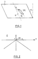
- A the prism angle
- i the angle of inclination of the prism on the glass G with respect to a straight line D passing through said glass and contained in a vertical plane
- DH the lateral deviation given by the prism, measured by distance from the point of impact of the ray refracted at the origin H in the normalized screen E, and by ⁇ the inclination of the glass relative to a vertical plane.
- each elementary prism is first of all characterized by its prism angle A determining the particular lateral deviation effected by this prism, and each time the angle of inclination i is calculated so that the refracted ray propagates without having been deflected vertically.
- This calculation of i as a function of A is repeated for a set of values A corresponding to the angular interval of deviation chosen, for example [0 °, 45 °].
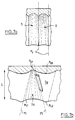
- a basic profile P0 is then defined, in this case an arc of a circle AC of determined radius R, which is contained in the plane x0y perpendicular to the plane of the ice and which tangents the plane of ice x0z.
- each elementary prism PE is adjusted in the plane of the glass so that the inclined surface of said prism comes to rest against (tangent) the arc of a circle AC, as illustrated in FIG. 3.
- i is a monotonic function increasing from A
- it is not at all a streak of frustoconical shape.
- the profiles of the groove in accordance with the present invention at different heights (z dimensions) are obtained by drawing at each dimension the curve which tangents all the inclined surfaces of the elementary prisms, as this is clearly shown in Figure 4.
- This curve can be characterized either by the set of coordinates of the various tangent points, accompanied by the set of derivatives of the curve (given directly by A) at these points, or again by an equation mathematics determined in such a way as to pass through these tangent points, having the corresponding derivatives at these points.
- Another solution can consist in using elementary prisms in progression according to a differential prism angle dA, then in calculating for each given profile of profile the coordinates of the points of the successive inclined surfaces of the elementary prisms, by making use of dA. If then one tends dA towards zero, one can obtain a mathematical definition of the profile considered.
- a hollow arc we used, as the base curve on which the prisms are based elementary, a hollow arc.
- any other curve with no slope break, recessed or full can be used, thereby forming a recessed or full streak, respectively.
- a conic arc such as a portion of ellipse, parabola or hyperbola.
- the curvature of the support arc, corresponding to the maximum curvature of the groove obtained, is also chosen to be compatible with conventional machining means.
- a set of couples (A, i) is first calculated in accordance with the indications given above.
- the profiles PR10 to PR30 can practically not be distinguished from the corresponding theoretical profiles.
- the same construction steps as in Example 1 were repeated.
- the profiles PR10 to PR30 can practically not be distinguished from the corresponding theoretical profiles.
- FIG. 7a there are illustrated two possible ways of juxtaposing on a closing glass streaks made in accordance with the present invention.
- the individual streaks S are delimited laterally by two vertical planes PV parallel to the plane y0z.
- streaks are produced which are alternately hollow and solid and separated by transition planes which have the same inclination as the marginal elementary prisms of said streaks.
- the groove S1 is produced as described above, that is to say that the support curve P01 is an arc of a circle (or other curve without a break in slope) concave located in the upper part of the groove .
- the immediately adjacent streak S2 is made with the same type of construction, but taking as support curve P L2 an arc of a circle (or other regular curve) convex located in the lower part of the streak.
- the streaks S1 and S2 are separated by an inclined transition plane PI which is perpendicular to the plane of the ice and which extends parallel to the inclination of the elementary prism border of each of the two streaks, having the maximum prism angle.
- an essential advantage of the present invention is that each streak, constructed from a multitude of rectilinear elementary prisms, is a ruled surface. This, combined with the fact that the profiles of the ridges can be approached with excellent precision by appropriate conic equations, considerably facilitates the production of the mold punch by a digital machining apparatus, and in particular greatly simplifies the configuration thereof.
- the groove surface according to the present invention is the only one which is both a regulated surface and a surface capable of giving a uniform deviation in any angular interval, in practically imparting no vertical drawdown, to a portion of light beam emitted towards the streak parallel to the optical axis of the projector.
- the present invention advantageously applies to windows which can be inclined not only with respect to the vertical, but also with respect to a horizontal transverse to the direction of movement of the vehicle, in correspondence with the receding edges of the front of the vehicle.
- ice plane means the plane tangent to the ice at the level of the streak considered.
Landscapes
- Engineering & Computer Science (AREA)
- General Engineering & Computer Science (AREA)
- Non-Portable Lighting Devices Or Systems Thereof (AREA)
- Optical Elements Other Than Lenses (AREA)
Claims (9)
- Verfahren zur Herstellung eines Formstempels für die Formung einer Scheinwerferscheibe mit einer Mehrzahl von Rillen für einen Kraftfahrzeugscheinwerfer, dadurch gekennzeichnet, daß es für jede Rille die folgenden Schritte umfaßt:
Definition einer Menge von geraden Elementarprismen (PE), die parallel zu einer Ebene der Scheinwerferscheibe ausgerichtet sind, wobei der prismenwinkel (A) und der Neigungswinkel (i) im Verhältnis zu einer vertikalen, senkrecht zu der Ebene der Scheinwerferscheibe angeordneten Ebene, für jedes Elementarprisma so gewählt sind, daß jeder parallel zu einer Bezugsachse verlaufende Lichtstrahl seitlich abgelenkt wird, ohne eine vertikale Ablenkung zu erfahren;
Definition einer Kurve ohne Steigungsunterbrechung (P₀) auf einer bestimmten Höhe der Scheinwerferscheibe und in einer Ebene (x0y), die senkrecht zur Ebene der Scheinwerferscheibe verläuft und diese entlang einer horizontalen Linie schneidet;
Abstimmung der Anordnungsstelle jedes Elementarprismas (PE), so daß seine Fläche tangential zu der genannten Kurve verläuft;
Berechnung der repräsentativen Daten einer Fläche, die tangential zu jeder dieser Elementarprismenflächen verläuft, deren Anordnungsstellen abgestimmt wurden, wobei diese Fläche die Fläche der Rille (S) bildet;
Bearbeitung des Formraums der Rille in dem Stempel nach Maßgabe der genannten Daten. - Verfahren nach Anspruch 1 , dadurch gekennzeichnet, daß die repräsentativen Daten der Rillenfläche aus einer Menge von kartesischen Koordinaten zu Tangentialpunkten mit Durchgang durch diese Fläche bestehen.
- Verfahren nach Anspruch 1 , dadurch gekennzeichnet, daß die repräsentativen Daten der Rillenfläche aus einer Menge von Gleichungen zu Kegelschnitten in einer Ebene bestehen, die senkrecht zu der Ebene der Scheinwerferscheibe verläuft und diese entlang einer horizontalen Linie schneidet.
- Verfahren nach Anspruch 1 bis 3 , dadurch gekennzeichnet, daß die genannte Kurve ohne Steigungsunterbrechung (P₀) aus der Gruppe ausgewählt wird, zu der Kreise, Parabeln, Hyperbeln und Ellipsen gehören.
- Verfahren zur Herstellung einer Scheibe für Kraftfahrzeugscheinwerfer , dadurch gekennzeichnet, daß die Formung der Scheibe (G) unter Verwendung eines Formstempels erfolgt, der durch das Verfahren nach einem der Ansprüche 1 bis 4 hergestellt wird.
- Scheibe für Kraftfahrzeugscheinwerfer, die sich für den Einbau in einer im Verhältnis zu einer vertikalen Ebene geneigten Position eignet, und in der Ausführung mit einer Mehrzahl von Rillen (S) für eine Verteilung des durch den Scheinwerfer abgestrahlten Lichts im wesentlichen in seitlicher Richtung , dadurch gekennzeichnet, daß jede Rille wenigstens einer bestimmten Rillengruppe eine Rillenregelfläche ohne Steigungsunterbrechung aufweist, deren Tangentialebenen eine Menge von Elementarprismen (PE) definieren, deren Prismenwinkel (A) und Neigungen (i) im Verhältnis zur Vertikalen sich entsprechend unterscheiden, so daß ein auf ein beliebiges Prisma einfallender Strahl durch dieses Prisma in einem je nach Prisma veränderlichen Maße seitlich abgelenkt wird, wobei er jedoch keine vertikale Ablenkung erfährt.
- Scheibe nach Anspruch 6 , dadurch gekennzeichnet, daß ein maximaler Krümmungsbereich jedes Prismas ein Querprofil (P₀) aufweist, das durch die Gleichung eines Kegelschnitts definiert ist.
- Scheibe nach einem der Ansprüche 6 und 7 , dadurch gekennzeichnet, daß sie in mindestens einem Bereich eine Abfolge von Rillen (S) umfaßt, die durch vertikale und senkrecht zur Ebene der Scheibe angeordnete Ebenen (PV) getrennt sind.
- Scheibe nach einem der Ansprüche 6 und 7 , dadurch gekennzeichnet, daß sie in mindestens einem Bereich eine Abfolge von abwechselnd vertieften und erhabenen Rillen (S1, S2) umfaßt, die ohne Steigungsunterbrechung in Ebenen (PI) miteinander verbunden sind, die senkrecht zur Ebene der Scheibe verlaufen und im Verhältnis zur Vertikalen geneigt sind.
Applications Claiming Priority (2)
| Application Number | Priority Date | Filing Date | Title |
|---|---|---|---|
| FR9005215A FR2661254B1 (fr) | 1990-04-24 | 1990-04-24 | Glace pour projecteur de vehicule automobile, procede de realisation d'un poincon de moule pour fabriquer ladite glace et procede de fabrication de la glace . |
| FR9005215 | 1990-04-24 |
Publications (2)
| Publication Number | Publication Date |
|---|---|
| EP0454563A1 EP0454563A1 (de) | 1991-10-30 |
| EP0454563B1 true EP0454563B1 (de) | 1994-08-17 |
Family
ID=9396033
Family Applications (1)
| Application Number | Title | Priority Date | Filing Date |
|---|---|---|---|
| EP91401067A Expired - Lifetime EP0454563B1 (de) | 1990-04-24 | 1991-04-23 | Scheibe für KFZ-Scheinwerfer und ihr Herstellungsverfahren |
Country Status (5)
| Country | Link |
|---|---|
| US (1) | US5132847A (de) |
| EP (1) | EP0454563B1 (de) |
| DE (1) | DE69103460T2 (de) |
| ES (1) | ES2062709T3 (de) |
| FR (1) | FR2661254B1 (de) |
Families Citing this family (3)
| Publication number | Priority date | Publication date | Assignee | Title |
|---|---|---|---|---|
| US5709451A (en) * | 1994-11-25 | 1998-01-20 | General Motors Corporation | High intensity descharge bulb parabolic reflector vehicle headlamp |
| FR2760067B1 (fr) * | 1997-02-21 | 1999-05-14 | Valeo Vision | Projecteur de vehicule automobile a miroir a zones juxtaposees lateralement, et procede de fabrication d'un tel miroir |
| FR2822550B1 (fr) * | 2001-03-21 | 2003-05-16 | Valeo Vision | Projecteur de vehicule automobile a miroir et element de deviation conjugues |
Family Cites Families (8)
| Publication number | Priority date | Publication date | Assignee | Title |
|---|---|---|---|---|
| GB813697A (en) * | 1956-02-29 | 1959-05-21 | Lund Lamps Ltd | Improvements relating to lamps for road vehicles |
| FR2175622B1 (de) * | 1972-03-16 | 1975-10-24 | Ducellier & Cie | |
| FR2282353A1 (fr) * | 1974-08-23 | 1976-03-19 | Cibie Projecteurs | Ensemble de projecteurs pour vehicule automobile |
| US3989495A (en) * | 1975-07-10 | 1976-11-02 | American Optical Corporation | Method of making optical prisms |
| FR2428204A1 (fr) * | 1978-06-09 | 1980-01-04 | Cibie Projecteurs | Perfectionnements aux glaces de projecteurs automobiles comportant des stries de deviation de lumiere |
| DE3048849C2 (de) * | 1980-10-01 | 1995-04-27 | Bosch Gmbh Robert | Streuscheibe für einen Scheinwerfer für Kraftfahrzeuge |
| US4338012A (en) * | 1980-10-31 | 1982-07-06 | Canon Kabushiki Kaisha | Focusing screen |
| US4930051A (en) * | 1989-04-07 | 1990-05-29 | General Electric Company | Headlamp with sloped lens including beam-spreading flutes |
-
1990
- 1990-04-24 FR FR9005215A patent/FR2661254B1/fr not_active Expired - Lifetime
-
1991
- 1991-04-23 ES ES91401067T patent/ES2062709T3/es not_active Expired - Lifetime
- 1991-04-23 DE DE69103460T patent/DE69103460T2/de not_active Expired - Fee Related
- 1991-04-23 US US07/690,054 patent/US5132847A/en not_active Expired - Fee Related
- 1991-04-23 EP EP91401067A patent/EP0454563B1/de not_active Expired - Lifetime
Also Published As
| Publication number | Publication date |
|---|---|
| FR2661254A1 (fr) | 1991-10-25 |
| FR2661254B1 (fr) | 1992-08-07 |
| US5132847A (en) | 1992-07-21 |
| EP0454563A1 (de) | 1991-10-30 |
| ES2062709T3 (es) | 1994-12-16 |
| DE69103460D1 (de) | 1994-09-22 |
| DE69103460T2 (de) | 1994-11-24 |
Similar Documents
| Publication | Publication Date | Title |
|---|---|---|
| EP2278217B1 (de) | Beleuchtungsmodul für Fahrzeugscheinwerfer, und mit wenigstens einem solchen Modul ausgerüsteter Scheinwerfer | |
| EP2743567B1 (de) | Optisches hauptelement, beleuchtungsmodul und scheinwerfer für kraftfahrzeug | |
| EP0290347B1 (de) | Hochleistungsleuchte, insbesondere für Kraftfahrzeuge | |
| EP3147557A1 (de) | Primäres optisches element für kraftfahrzeugsbeleuchtungsmodul | |
| WO2022129625A1 (fr) | Projecteur automobile avec plusieurs modules d'éclairage sur une platine commune inclinée | |
| FR2910592A1 (fr) | Module de projecteur lumineux de vehicule automobile pour un faisceau a coupure | |
| FR3012867A1 (fr) | Element optique primaire, module lumineux et projecteur pour vehicule automobile | |
| FR3010772A1 (fr) | Dispositif d'emission de lumiere pour projecteur de vehicule automobile | |
| EP2607778A1 (de) | Beleuchtungssystem für Scheinwerfer, insbesondere eines Kraftfahrzeugs | |
| FR3103253A1 (fr) | Module lumineux combine imageant la surface eclairée d’un collecteur | |
| EP2597360A1 (de) | Lichtemittierende Einrichtung für Kraftfahrzeugscheinwerfer | |
| FR3002022A1 (fr) | Dispositif d'eclairage et/ou de signalisation a lentille torique | |
| FR2745365A1 (fr) | Feu de signalisation a moyens perfectionnes d'etalement de la lumiere | |
| FR2614969A1 (fr) | Feu de signalisation a grande plage eclairante et luminance homogene, notamment pour vehicule automobile | |
| FR2752910A1 (fr) | Installation d'eclairage pour vehicule automobile | |
| EP3470727A1 (de) | Beleuchtungsmodul, das ein lichtmuster bildet, dessen oberer teil scharfe vertikale kanten und dessen unterer teil unscharfe vertikale kanten aufweist | |
| EP1243846B1 (de) | Kraftfahrzeugprojektor mit Spiegel und konjugiertem Umlenkelement und Verfahren zur Herstellung desselben | |
| EP4264123B1 (de) | Beleuchtungsvorrichtung mit doppelfunktion und rotierender linse | |
| EP0966633B1 (de) | Kfz-scheinwerfer mit elliptischem reflektor | |
| EP0454563A1 (de) | Scheibe für KFZ-Scheinwerfer und ihr Herstellungsverfahren | |
| EP4045841A1 (de) | Optisches system | |
| EP2199662B1 (de) | Verbesserter Beleuchtungsmodul für Kraftfahrzeuge | |
| EP0735309B1 (de) | Herstellungsverfahren eines Reflektors für Kfz-Scheinwerfer und Kfz-Schweinwerfer mit einem das Licht selektiv ablenkenden Reflektor | |
| FR2837908A1 (fr) | Projecteur d'eclairage equipe d'un reflecteur elliptique pivotant et d'une lentille fixe pour la realisation d'un faisceau de virage | |
| EP2650600A1 (de) | Lichtwellenleiter für eine Leuchtvorrichtung eines Kraftfahrzeugs |
Legal Events
| Date | Code | Title | Description |
|---|---|---|---|
| PUAI | Public reference made under article 153(3) epc to a published international application that has entered the european phase |
Free format text: ORIGINAL CODE: 0009012 |
|
| AK | Designated contracting states |
Kind code of ref document: A1 Designated state(s): DE ES GB IT |
|
| 17P | Request for examination filed |
Effective date: 19920217 |
|
| 17Q | First examination report despatched |
Effective date: 19931004 |
|
| RAP1 | Party data changed (applicant data changed or rights of an application transferred) |
Owner name: VALEO VISION |
|
| GRAA | (expected) grant |
Free format text: ORIGINAL CODE: 0009210 |
|
| AK | Designated contracting states |
Kind code of ref document: B1 Designated state(s): DE ES GB IT |
|
| REF | Corresponds to: |
Ref document number: 69103460 Country of ref document: DE Date of ref document: 19940922 |
|
| GBT | Gb: translation of ep patent filed (gb section 77(6)(a)/1977) |
Effective date: 19940901 |
|
| ITF | It: translation for a ep patent filed | ||
| REG | Reference to a national code |
Ref country code: ES Ref legal event code: FG2A Ref document number: 2062709 Country of ref document: ES Kind code of ref document: T3 |
|
| PGFP | Annual fee paid to national office [announced via postgrant information from national office to epo] |
Ref country code: GB Payment date: 19950330 Year of fee payment: 5 |
|
| PGFP | Annual fee paid to national office [announced via postgrant information from national office to epo] |
Ref country code: ES Payment date: 19950412 Year of fee payment: 5 |
|
| PGFP | Annual fee paid to national office [announced via postgrant information from national office to epo] |
Ref country code: DE Payment date: 19950613 Year of fee payment: 5 |
|
| PLBE | No opposition filed within time limit |
Free format text: ORIGINAL CODE: 0009261 |
|
| STAA | Information on the status of an ep patent application or granted ep patent |
Free format text: STATUS: NO OPPOSITION FILED WITHIN TIME LIMIT |
|
| 26N | No opposition filed | ||
| PG25 | Lapsed in a contracting state [announced via postgrant information from national office to epo] |
Ref country code: GB Effective date: 19960423 |
|
| PG25 | Lapsed in a contracting state [announced via postgrant information from national office to epo] |
Ref country code: ES Free format text: LAPSE BECAUSE OF NON-PAYMENT OF DUE FEES Effective date: 19960424 |
|
| GBPC | Gb: european patent ceased through non-payment of renewal fee |
Effective date: 19960423 |
|
| PG25 | Lapsed in a contracting state [announced via postgrant information from national office to epo] |
Ref country code: DE Effective date: 19970101 |
|
| REG | Reference to a national code |
Ref country code: ES Ref legal event code: FD2A Effective date: 19990503 |
|
| PG25 | Lapsed in a contracting state [announced via postgrant information from national office to epo] |
Ref country code: IT Free format text: LAPSE BECAUSE OF NON-PAYMENT OF DUE FEES Effective date: 20050423 |