EP0453740B1 - Dispositif de logement pour sac à air - Google Patents
Dispositif de logement pour sac à air Download PDFInfo
- Publication number
- EP0453740B1 EP0453740B1 EP91103493A EP91103493A EP0453740B1 EP 0453740 B1 EP0453740 B1 EP 0453740B1 EP 91103493 A EP91103493 A EP 91103493A EP 91103493 A EP91103493 A EP 91103493A EP 0453740 B1 EP0453740 B1 EP 0453740B1
- Authority
- EP
- European Patent Office
- Prior art keywords
- covering
- hinge
- air bag
- arrangement according
- container
- Prior art date
- Legal status (The legal status is an assumption and is not a legal conclusion. Google has not performed a legal analysis and makes no representation as to the accuracy of the status listed.)
- Expired - Lifetime
Links
Images

Classifications
-
- B—PERFORMING OPERATIONS; TRANSPORTING
- B60—VEHICLES IN GENERAL
- B60R—VEHICLES, VEHICLE FITTINGS, OR VEHICLE PARTS, NOT OTHERWISE PROVIDED FOR
- B60R21/00—Arrangements or fittings on vehicles for protecting or preventing injuries to occupants or pedestrians in case of accidents or other traffic risks
- B60R21/02—Occupant safety arrangements or fittings, e.g. crash pads
- B60R21/16—Inflatable occupant restraints or confinements designed to inflate upon impact or impending impact, e.g. air bags
- B60R21/20—Arrangements for storing inflatable members in their non-use or deflated condition; Arrangement or mounting of air bag modules or components
- B60R21/215—Arrangements for storing inflatable members in their non-use or deflated condition; Arrangement or mounting of air bag modules or components characterised by the covers for the inflatable member
- B60R21/2165—Arrangements for storing inflatable members in their non-use or deflated condition; Arrangement or mounting of air bag modules or components characterised by the covers for the inflatable member characterised by a tear line for defining a deployment opening
- B60R21/21656—Steering wheel covers or similar cup-shaped covers
-
- B—PERFORMING OPERATIONS; TRANSPORTING
- B60—VEHICLES IN GENERAL
- B60R—VEHICLES, VEHICLE FITTINGS, OR VEHICLE PARTS, NOT OTHERWISE PROVIDED FOR
- B60R21/00—Arrangements or fittings on vehicles for protecting or preventing injuries to occupants or pedestrians in case of accidents or other traffic risks
- B60R21/02—Occupant safety arrangements or fittings, e.g. crash pads
- B60R21/16—Inflatable occupant restraints or confinements designed to inflate upon impact or impending impact, e.g. air bags
- B60R2021/161—Inflatable occupant restraints or confinements designed to inflate upon impact or impending impact, e.g. air bags characterised by additional means for controlling deployment trajectory
Definitions
- the invention relates to a receiving device for an airbag according to the preamble of claim 1.
- a receiving device for an airbag according to the preamble of claim 1.
- Such a construction is e.g. known from US-A-4 903 986.
- the cover has a transverse hinge in a lower edge area due to a slot-like notch in the cover profile, so that the cover can be folded away against the vehicle floor when the airbag is deployed.
- the airbag which is inflated by a gas generator in fractions of a second, presses against the inside of the cover with great force, as a result of which the cover is catapulted and the airbag fabric emerges at high speed in the direction of a vehicle occupant.
- the invention has for its object to reduce the impulse of an airbag when it is deployed in the direction of a vehicle occupant by a generic cover.
- the side cover flaps of the cover open first when the airbag unfolds from the side regions of the airbag container, as a result of which the airbag has already reached a certain filling volume before the entire cover folds away from the container opening. This delays the movement of the airbag in the middle area compared to the side areas. The development impulse of the airbag, which unfolds very quickly, is thereby weakened in the middle area of the airbag.
- This opening mechanism can be controlled solely by the method of folding the airbag into the airbag container, but it is also possible to control such a process by means of additional control connections of the cover with the triggering mechanism of the gas generator.
- the tear-open edges around the side cover flaps can be worked deeper into the cover material than the tear-open edge, which finally releases a pivoting movement of the complete cover, and / or the hinges of the pivotable cover and the two side cover flaps are to be provided in such a way that the last one can be pivoted away Cover in the hinge has a higher resistance to the opening movement than the hinges of the side cover flaps. This resistance can be influenced by an insert strip attached to the inside of the cover.
- the airbag container with the hinged cover is fixed in a steering wheel, it is advantageous to arrange it in such a way that it does not protrude over the steering wheel rim after the airbag has been deployed.
- a vehicle occupant (not shown) who could be sitting on a seat 1 is to be protected from an impact on vehicle interior parts 3 and in this case in particular on a steering wheel 4 with a steering wheel rim 5 by an expanding airbag 2 in the event of a vehicle accident.
- the airbag 2 is folded into an airbag container 6, which is fixed on a steering wheel hub within the steering wheel rim 5.
- this receiving device for the airbag 2 comprises a flat cover 7, which is fixed to a base plate, which is formed here by the airbag container 6 itself, and which covers the airbag container 6 over the folded airbag 2.
- a gas generator 1 (not shown in detail) at the bottom of the airbag container 6, through which gas flows into the sack fabric 8, the cover 7 is opened along a hinge axis of a hinge 9 in the lower edge region, after which it opens a container opening 10 for the Passes through the bag fabric 8 in an inflated position in front of the vehicle occupant.
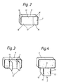
- the cover 7 also has two further, approximately vertical hinges 11, which are at a distance from the side edges 12 of the cover 7, as a result of which two side cover flaps 13 which subdivide the pivotable cover 7 are formed.
- the hinge 9 of the cover 7 is limited by these two cover flaps 13.
- a deployment process of the airbag 2 is controlled, during which several folded positions of the airbag 2 are first unfolded only in lateral areas 14 and partially emerge from the airbag container 6, and only then the cover 7 by the pressure of the airbag 2 on the The inside of the cover is pivoted completely away from the container opening 10.
- This opening process of the cover is continuously outlined in FIGS. 2 to 4. Because the central region of the airbag 2 can only be deployed with a delay compared to its lateral regions and can be filled in front of the vehicle occupant, the deployment pulse in the central airbag region has a reduced effect on the vehicle occupant.
- the side cover flaps 13 are opened along the tear edges 16 by the load on the inside of the cover with the unfolding airbag 2. These have less resistance to tearing than the transverse tear edge 17.
- the opening forces of the tear-open edges 16, 17 can be varied and coordinated in a simple manner, for example, by different notch depths on the inside or outside of the cover.
- the opening mechanism can be influenced by the formation of the hinges 9, 11 themselves, which have, for example, a certain notch depth on the inside of the cover profile, or contain insert strips 15, for example made of fabric, aluminum or steel, which run along the hinges 9, 11 bridge their longitudinal axis, thereby reinforcing them and thereby also being able to increase the resistance to opening, as a result of which the opening speed of the flaps 7 and 13 can be varied.
- insert strips 15 can also be foamed into the covering material, so that the flaps break open along their intended hinge axis, are held by the insert strip 15 on the airbag container 6, and the insert strip 15 can influence the speed of their opening movement.
- the cover 7 is arranged such that it lies in the folded-away open position within the steering wheel rim 5.
Landscapes
- Engineering & Computer Science (AREA)
- Mechanical Engineering (AREA)
- Air Bags (AREA)
Claims (7)
- Dispositif de logement pour sac à air (2), protégeant un passager contre un choc sur les parties de l'habitacle du véhicule, avec un recouvrement (7) rectangulaire, dont les côtés longs du rectangle sont orientés transversalement par rapport à la direction du véhicule lorsqu'on roule en ligne droite et recouvrant un récipient à sac à air (6), en étant fixé sur une plaque de base et qui, pendant le déploiement du sac à air (2), s'ouvre par rabattement le long d'un axe de charnière transversal, dans la zone de bordure inférieure du récipient de sac à air (6), puis libère entièrement une ouverture de récipient (10), donnant passage à la structure de sac (8), en une position gonflée, devant les passagers, caractérisé en ce que le recouvrement (7) présente, outre la première charnière (9) située transversalement et au-dessous, deux autres charnières (11), assurant une limitation sur les deux côtés, à peu près perpendiculaire à la première charnière (9) et présentant un espacement, par rapport aux bordures latérales (12) du recouvrement (7), faisant que sont formés deux volets de recouvrement latéraux (13), subdivisant le recouvrement pivotant (7) et que, suite à une sollicitation de la face intérieure du recouvrement par le sac à air (2) qui se déploie, il se produit d'abord un écartement par rapport à l'ouverture de récipient (10), par pivotement des volets de recouvrement latéraux (13) et ensuite de l'ensemble du recouvrement (7), autour de la charnière (9) située transversalement au-dessous.
- Dispositif de logement selon la revendication 1, caractérisé en ce que, par une sollicitation de la face intérieure de recouvrement, par le sac à air (2) en train de se déployer, se produit d'abord un écartement, par rapport à l'ouverture de récipient (10), par pivotement des volets de recouvrement (13) latéraux, puis de l'ensemble du recouvrement (7).
- Dispositif de logement selon la revendication 2, caractérisé en ce que la charnière (9) du recouvrement (7) offre une résistance à l'ouverture par rabattement plus élevée que le font les deux charnières (11) des volets de recouvrement (13).
- Dispositif de logement selon l'une des revendications précédentes, caractérisé en ce que la charnière (9, respectivement 11) est formée par des entailles linéaires formées dans le profil de recouvrement.
- Dispositif de logement selon l'une des revendications précédentes, caractérisé en ce que la charnière (9 respectivement 11) est renforcée par des bandes de garnitures (15) fixées sur la face intérieure du recouvrement.
- Dispositif de logement selon la revendication 5, caractérisé en ce que la vitesse d'ouverture d'un volet (7 respectivement 13) peut être influencée au moyen des bandes de garnitures (15).
- Dispositif de logement selon la revendication 1, caractérisé en ce que le récipient à sac (6) est fixé dans un volant (4), de telle façon que le recouvrement (7) est situé à l'intérieur de l'arceau de volant (5), lorsque le recouvrement (7) est dans la position écartée par ouverture.
Applications Claiming Priority (2)
| Application Number | Priority Date | Filing Date | Title |
|---|---|---|---|
| DE4010766A DE4010766A1 (de) | 1990-04-04 | 1990-04-04 | Aufnahmevorrichtung fuer einen luftsack |
| DE4010766 | 1990-04-04 |
Publications (2)
| Publication Number | Publication Date |
|---|---|
| EP0453740A1 EP0453740A1 (fr) | 1991-10-30 |
| EP0453740B1 true EP0453740B1 (fr) | 1993-08-25 |
Family
ID=6403683
Family Applications (1)
| Application Number | Title | Priority Date | Filing Date |
|---|---|---|---|
| EP91103493A Expired - Lifetime EP0453740B1 (fr) | 1990-04-04 | 1991-03-07 | Dispositif de logement pour sac à air |
Country Status (4)
| Country | Link |
|---|---|
| US (1) | US5135255A (fr) |
| EP (1) | EP0453740B1 (fr) |
| JP (1) | JP2545003B2 (fr) |
| DE (2) | DE4010766A1 (fr) |
Families Citing this family (9)
| Publication number | Priority date | Publication date | Assignee | Title |
|---|---|---|---|---|
| JPH05246293A (ja) * | 1992-03-10 | 1993-09-24 | Takata Kk | 助手席用エアバッグ装置 |
| US5320381A (en) * | 1993-07-02 | 1994-06-14 | General Motors Corporation | Air bag deployment door hinge |
| US5348343A (en) * | 1993-11-01 | 1994-09-20 | General Motors Corporation | Air bag deployment bias apparatus |
| US5513879A (en) * | 1994-05-04 | 1996-05-07 | Breed Automotive Technology, Inc. | Two stage inflator with module venting for passenger side airbags |
| US5560648A (en) * | 1995-08-24 | 1996-10-01 | General Motors Corporation | Air bag deployment bias apparatus |
| US5630614A (en) * | 1995-11-13 | 1997-05-20 | General Motors Corporation | Bias apparatus for air bag module |
| US5678853A (en) * | 1996-06-26 | 1997-10-21 | Morton International, Inc. | Airbag module with deployment chute |
| US6793238B2 (en) | 2002-03-20 | 2004-09-21 | Autoliv Asp, Inc. | Airbag covers for multi-axis deployment |
| US6848705B2 (en) | 2002-03-20 | 2005-02-01 | Autoliv Asp, Inc. | Airbag cover with multi-axis deployment |
Family Cites Families (7)
| Publication number | Priority date | Publication date | Assignee | Title |
|---|---|---|---|---|
| US3622176A (en) * | 1970-02-05 | 1971-11-23 | Ford Motor Co | Motor vehicle instrument panel element |
| US3794349A (en) * | 1972-05-19 | 1974-02-26 | Gen Motors Corp | Occupant restraint system |
| JPS52116537A (en) * | 1976-03-26 | 1977-09-30 | Toyota Motor Corp | Expansion type passenger restricting device for automobile or the like |
| DE2905618A1 (de) * | 1979-02-14 | 1980-08-21 | Daimler Benz Ag | Auf eine grundplatte aufklipsbare kappenartige abdeckung |
| JPH01144153U (fr) * | 1988-03-11 | 1989-10-03 | ||
| US4903986A (en) * | 1988-11-14 | 1990-02-27 | General Motors Corporation | Modular occupant restraint system |
| US5013064A (en) * | 1990-05-29 | 1991-05-07 | General Motors Corporation | Occupant restraint system |
-
1990
- 1990-04-04 DE DE4010766A patent/DE4010766A1/de not_active Withdrawn
-
1991
- 1991-03-07 EP EP91103493A patent/EP0453740B1/fr not_active Expired - Lifetime
- 1991-03-07 DE DE91103493T patent/DE59100313D1/de not_active Expired - Fee Related
- 1991-03-28 JP JP3133662A patent/JP2545003B2/ja not_active Expired - Lifetime
- 1991-04-04 US US07/680,571 patent/US5135255A/en not_active Expired - Lifetime
Also Published As
| Publication number | Publication date |
|---|---|
| JPH0769153A (ja) | 1995-03-14 |
| DE4010766A1 (de) | 1991-10-17 |
| US5135255A (en) | 1992-08-04 |
| DE59100313D1 (de) | 1993-09-30 |
| EP0453740A1 (fr) | 1991-10-30 |
| JP2545003B2 (ja) | 1996-10-16 |
Similar Documents
| Publication | Publication Date | Title |
|---|---|---|
| DE4304152C2 (de) | Seitenaufprallschutzvorrichtung für einen Fahrzeuginsassen | |
| EP0714818B1 (fr) | Coussin gonflable pour collision latérale | |
| DE69928117T2 (de) | Airbag mit umlenkvorrichtung und einer in ihren volumen expandierbaren kammer | |
| DE60012340T2 (de) | Airbagvorrichtung | |
| DE60305374T2 (de) | Insassenbeinschutzvorrichtung | |
| EP0501040B1 (fr) | Plancher d'habitacle de véhicule, dont au moins une partie consiste d'un matériau à zone de rupture | |
| DE2104109A1 (de) | Instrumentenbrettabdeckung fur ein Kraftfahrzeug | |
| DE20080100U1 (de) | Airbagmodul für Lenkräder | |
| DE112009002218T5 (de) | Airbag Modul | |
| EP0646499B1 (fr) | Tableau de bord dans une automobile | |
| DE4418582A1 (de) | Instrumententafel in einem Kraftwagen | |
| EP1112898B1 (fr) | Volant avec un couvercle pour module de coussin gonflable | |
| DE202021104563U1 (de) | Fahrerairbagvorrichtung für ein Fahrzeug | |
| DE69412671T2 (de) | Luftsack-Deckel | |
| DE10137824C2 (de) | Insassenrückhaltesystem im Fondbereich eines Kraftfahrzeugs | |
| DE10063473A1 (de) | Dachholm-Verkleidung für aufblasbares Rückhaltesystem | |
| EP0453740A1 (fr) | Dispositif de logement pour sac à air | |
| DE10065565B4 (de) | Airbag-Abdeckung in einem Kraftfahrzeug | |
| DE29601257U1 (de) | Airbag | |
| EP0856436B1 (fr) | Système protège-genoux pour le passager d'un véhicule automobile | |
| EP0953485B1 (fr) | Dispositif de protection en cas d'accident | |
| DE19546001C2 (de) | Scharniergehalterte Abdeckklappe für eine Airbag-Anordnung | |
| DE10257248A1 (de) | Kraftfahrzeug mit einer Karosseriestruktur und mit einer Seitenaufprallschutzeinrichtung | |
| EP1113949B1 (fr) | Module sac gonflable doté d'un générateur de gaz à plusieurs étapes | |
| DE69933451T2 (de) | Airbaganordnung zum seitlichen Schutz eines Insassen eines Kraftfahrzeugs |
Legal Events
| Date | Code | Title | Description |
|---|---|---|---|
| ITTA | It: last paid annual fee | ||
| PUAI | Public reference made under article 153(3) epc to a published international application that has entered the european phase |
Free format text: ORIGINAL CODE: 0009012 |
|
| 17P | Request for examination filed |
Effective date: 19910809 |
|
| AK | Designated contracting states |
Kind code of ref document: A1 Designated state(s): DE FR GB IT SE |
|
| 17Q | First examination report despatched |
Effective date: 19930121 |
|
| ITF | It: translation for a ep patent filed | ||
| GRAA | (expected) grant |
Free format text: ORIGINAL CODE: 0009210 |
|
| AK | Designated contracting states |
Kind code of ref document: B1 Designated state(s): DE FR GB IT SE |
|
| REF | Corresponds to: |
Ref document number: 59100313 Country of ref document: DE Date of ref document: 19930930 |
|
| GBT | Gb: translation of ep patent filed (gb section 77(6)(a)/1977) |
Effective date: 19930917 |
|
| ET | Fr: translation filed | ||
| PLBE | No opposition filed within time limit |
Free format text: ORIGINAL CODE: 0009261 |
|
| STAA | Information on the status of an ep patent application or granted ep patent |
Free format text: STATUS: NO OPPOSITION FILED WITHIN TIME LIMIT |
|
| 26N | No opposition filed | ||
| EAL | Se: european patent in force in sweden |
Ref document number: 91103493.2 |
|
| REG | Reference to a national code |
Ref country code: FR Ref legal event code: TP |
|
| REG | Reference to a national code |
Ref country code: GB Ref legal event code: 732E |
|
| REG | Reference to a national code |
Ref country code: GB Ref legal event code: 732E |
|
| PGFP | Annual fee paid to national office [announced via postgrant information from national office to epo] |
Ref country code: GB Payment date: 20000216 Year of fee payment: 10 |
|
| PGFP | Annual fee paid to national office [announced via postgrant information from national office to epo] |
Ref country code: FR Payment date: 20000322 Year of fee payment: 10 |
|
| PGFP | Annual fee paid to national office [announced via postgrant information from national office to epo] |
Ref country code: SE Payment date: 20000323 Year of fee payment: 10 |
|
| REG | Reference to a national code |
Ref country code: GB Ref legal event code: 746 Effective date: 20000309 |
|
| REG | Reference to a national code |
Ref country code: FR Ref legal event code: TP Ref country code: FR Ref legal event code: D6 |
|
| PG25 | Lapsed in a contracting state [announced via postgrant information from national office to epo] |
Ref country code: GB Free format text: LAPSE BECAUSE OF NON-PAYMENT OF DUE FEES Effective date: 20010307 |
|
| PG25 | Lapsed in a contracting state [announced via postgrant information from national office to epo] |
Ref country code: SE Free format text: LAPSE BECAUSE OF NON-PAYMENT OF DUE FEES Effective date: 20010308 |
|
| GBPC | Gb: european patent ceased through non-payment of renewal fee |
Effective date: 20010307 |
|
| EUG | Se: european patent has lapsed |
Ref document number: 91103493.2 |
|
| PG25 | Lapsed in a contracting state [announced via postgrant information from national office to epo] |
Ref country code: FR Free format text: LAPSE BECAUSE OF NON-PAYMENT OF DUE FEES Effective date: 20011130 |
|
| REG | Reference to a national code |
Ref country code: FR Ref legal event code: ST |
|
| PG25 | Lapsed in a contracting state [announced via postgrant information from national office to epo] |
Ref country code: IT Free format text: LAPSE BECAUSE OF NON-PAYMENT OF DUE FEES;WARNING: LAPSES OF ITALIAN PATENTS WITH EFFECTIVE DATE BEFORE 2007 MAY HAVE OCCURRED AT ANY TIME BEFORE 2007. THE CORRECT EFFECTIVE DATE MAY BE DIFFERENT FROM THE ONE RECORDED. Effective date: 20050307 |
|
| PGFP | Annual fee paid to national office [announced via postgrant information from national office to epo] |
Ref country code: DE Payment date: 20060314 Year of fee payment: 16 |
|
| PG25 | Lapsed in a contracting state [announced via postgrant information from national office to epo] |
Ref country code: DE Free format text: LAPSE BECAUSE OF NON-PAYMENT OF DUE FEES Effective date: 20071002 |