EP0452730B1 - Mould with pivoting, radially opening segments - Google Patents
Mould with pivoting, radially opening segments Download PDFInfo
- Publication number
- EP0452730B1 EP0452730B1 EP91105202A EP91105202A EP0452730B1 EP 0452730 B1 EP0452730 B1 EP 0452730B1 EP 91105202 A EP91105202 A EP 91105202A EP 91105202 A EP91105202 A EP 91105202A EP 0452730 B1 EP0452730 B1 EP 0452730B1
- Authority
- EP
- European Patent Office
- Prior art keywords
- mold
- sectors
- sector
- molding
- recess
- Prior art date
- Legal status (The legal status is an assumption and is not a legal conclusion. Google has not performed a legal analysis and makes no representation as to the accuracy of the status listed.)
- Expired - Lifetime
Links
- 238000000465 moulding Methods 0.000 claims description 36
- 230000000295 complement effect Effects 0.000 claims description 2
- 230000000149 penetrating effect Effects 0.000 claims 1
- 230000009471 action Effects 0.000 description 5
- 230000002093 peripheral effect Effects 0.000 description 3
- 230000008901 benefit Effects 0.000 description 2
- 238000004073 vulcanization Methods 0.000 description 2
- 230000005540 biological transmission Effects 0.000 description 1
- 230000007547 defect Effects 0.000 description 1
- 230000000694 effects Effects 0.000 description 1
- 230000002349 favourable effect Effects 0.000 description 1
- 239000013529 heat transfer fluid Substances 0.000 description 1
- 230000006872 improvement Effects 0.000 description 1
- 238000003754 machining Methods 0.000 description 1
- 230000007246 mechanism Effects 0.000 description 1
- 238000000034 method Methods 0.000 description 1
- 238000012986 modification Methods 0.000 description 1
- 230000004048 modification Effects 0.000 description 1
- 238000005096 rolling process Methods 0.000 description 1
Images


Classifications
-
- B—PERFORMING OPERATIONS; TRANSPORTING
- B29—WORKING OF PLASTICS; WORKING OF SUBSTANCES IN A PLASTIC STATE IN GENERAL
- B29D—PRODUCING PARTICULAR ARTICLES FROM PLASTICS OR FROM SUBSTANCES IN A PLASTIC STATE
- B29D30/00—Producing pneumatic or solid tyres or parts thereof
- B29D30/06—Pneumatic tyres or parts thereof (e.g. produced by casting, moulding, compression moulding, injection moulding, centrifugal casting)
- B29D30/0601—Vulcanising tyres; Vulcanising presses for tyres
- B29D30/0606—Vulcanising moulds not integral with vulcanising presses
- B29D30/0629—Vulcanising moulds not integral with vulcanising presses with radially movable sectors
Definitions
- the present invention relates to sector molds for tires, in particular to molds as described in patent application FR 2 342 153.
- This type of mold includes a lower molding part, an upper molding part, and a series of sectors for molding, respectively, a sidewall, the other sidewall, and the tread of the tire.
- the mold has a peripheral hoop surrounding the sectors, causing their radial closing movement (bringing radially towards the center of all the sectors) and keeping them firmly closed to resist the molding pressure.
- the opening of the mold in addition to appropriate kinematics, calls upon the action of springs to move the sectors back, that is to say move them away from the center of the mold, and to make them tilt slightly.
- the recoil movement is caused by slides of the "dovetail" type and this type of control is incompatible with the tilting of the sector.
- the invention aims to reconcile the purely radial recoil movement during the mold release phase of the sculpture occurring at the very beginning of the recoil, with a subsequent tilting of the sectors, in order to keep the space requirement as small as possible.
- the sector mold for molding and vulcanizing tires of the type comprising a lower molding part for molding a sidewall of the tire, an upper molding part for molding the other sidewall, and a series of sectors for molding the tread, as well as a closing and shrinking crown of the series of sectors,: the crown comprising an inclined face, the opening and closing movements implying a radial recoil of the sectors and a tilting of the end of the sectors towards the outside, as well as an elevation of the upper molding part, the radially outer face of each sector being inclined so as to cooperate with the complementary inclined face of said crown, said crown being able to be raised and lowered separately from the upper molding part, each sector being permanently returned to the retracted position and tilted by one or more springs, is characterized in that each sector is provided with at least one horizontal protuberance developing radially beyond said inclined face, each protuberance being pierced by a housing, and in that the crown comprises, in correspondence with each housing, a inclined rod arranged so as to
- the lower molding part is integral with the fixed lower plate of the press; the upper molding part is secured to an upper plate, movable along the axis of the mold.
- the closing crown is integral with a mechanism which ensures its movement along the axis of the mold, separately from the previous movement.
- the radially inner face of the closure crown is generally a frustoconical face.
- the radially outer face of the sectors, which cooperates, as is well known, with the closing crown, is also frustoconical and corresponds exactly to said radially inner face of the crown.
- the inclination of the trunks of cones is such that, at from a position separated from the sectors, a lowering of the crown, by a movement parallel to the axis of the mold in a direction going from the upper plate towards the lower plate, by the sliding of the frustoconical faces one on the another causes the sectors to move in the radial direction towards their closed position.
- the lower molding part 10 made integral with the lower plate 11, the upper molding part 20, a sector 30 of the series of sectors ensuring the molding of the tread.
- This sector 30 consists of a support part 31, and of a part 32 ensuring the molding of the tread.
- the sector 30 has a frustoconical face 33 inclined at an angle ⁇ .
- Sliding plates 34 are screwed onto the upper end 35 of sector 30, to promote the sliding of sector 30 along the upper molding part 20, and also to limit the wear that could cause contact between sector 30 and part upper molding 20 occurring in the kinematics of closing the mold.
- the peripheral ring 40 has a radially frustoconical inner face 41, the inclination of which is identical to the inclination ⁇ of the face 33 of the sectors 30.
- the internal cavity 42 allows the circulation of a heat transfer fluid for vulcanization.
- the sectors 30 are permanently stressed by springs 50, 51, in tilting and in radial recoil.
- Each spring 50 is disposed in a recess 12 provided in the lower plate 11.
- Each spring 50 tends to push upward a pusher 52 whose stroke is limited by a stop 53 fixed on the lower plate 11.
- the pusher 52 acts on the lower part 36 of the sector 30, at the radially inner end thereof.
- the tension springs 51 constantly tend to move the sectors 30 back towards their open position, and this radial recoil is limited by the crown 40, as well as by the axis 6 integral with each sector 30.
- the central part 61 of the axis 6 can slide in a buttonhole 13 delimiting the radial clearance authorized for axis 6.
- Each sector 30 comprises two plates 37 attached by screwing in the lower part 36.
- the shear pins 62 ensure the transmission of the forces from the plates 37 to the sectors 30.
- Each plate 37 forms a horizontal protuberance 30 developing radially beyond the face 33 inclined forming the back of each sector 30.
- a housing 39 is drilled through of each plate 37, at the level of said protuberance 38.
- the crown 40 comprises an inclined rod 43 extending axially downward relative to the crown 40.
- the operation of the mold is as follows. After having introduced the tire 1 to be vulcanized, the upper molding part 20 and the crown 40 are lowered according to the usual procedure for this type of mold.
- the specific means of the present invention namely the plates 37 and the rods 43, do not have to intervene to ensure said mold closure. It can be seen in FIG. 3 that the rods 43 can freely enter the housings 39 without coming into contact with the plates 37.
- FIG. 4 shows the mold completely closed: there remains a radial clearance J between the radially outer side of each rod, and the corresponding edge 16 of the housing 39.
- To open the mold it is first necessary, while keeping the upper plate stationary (therefore the upper molding part 20) to raise the crown 40. It can be seen in FIG.
- the rods 43 cause traction on the sectors 30 and therefore force the purely radial recoil movement favorable to the correct release of the tread from the mold, without causing defects on that -this.
- the inclination ⁇ made by the rods 43 is less than the inclination ⁇ of the frustoconical faces 41 and 33, which, added to the clearance J, prevents any jamming at the opening, and prevents any collision between pieces at closing.
- FIGS 3 '4', 5 'and 7' show an alternative embodiment of the plates 37.
- the sliding friction of the rods 43 on the edge 16 is replaced by a rolling friction.
- a wear roller 14 is mounted which is movable in rotation on an axis 15 disposed at the end of the plates 37 and closing the housing 39. This variant allows an adjustment of the clearance J by varying the diameter of the roller d wear 14.
- the upper molding part 20 can be raised and the continuation of the opening movement of the sectors is ensured, as known, by springs 50 and 51.
- the invention requires only a minimum of modifications to known molds and therefore makes it possible to ensure a gain. important in the quality of molded tires with a minimum of investment.
- the control of the radial recoil does not require great precision in machining and / or mounting, which again constitutes an advantage of the present invention.
Landscapes
- Engineering & Computer Science (AREA)
- Mechanical Engineering (AREA)
- Moulds For Moulding Plastics Or The Like (AREA)
- Heating, Cooling, Or Curing Plastics Or The Like In General (AREA)
- Pens And Brushes (AREA)
- Soil Working Implements (AREA)
- Toys (AREA)
- Mirrors, Picture Frames, Photograph Stands, And Related Fastening Devices (AREA)
- Hinges (AREA)
- Chairs Characterized By Structure (AREA)
- Moulding By Coating Moulds (AREA)
- Casting Or Compression Moulding Of Plastics Or The Like (AREA)
Abstract
Description
La présente invention se rapporte aux moules à secteurs pour pneumatiques, en particulier aux moules tels que décrits dans la demande de brevet FR 2 342 153.The present invention relates to sector molds for tires, in particular to molds as described in patent application FR 2 342 153.
Ce type de moule comporte une partie moulante inférieure, une partie moulante supérieure, et une série de secteurs pour assurer le moulage, respectivement, d'un flanc, de l'autre flanc, et de la bande de roulement du pneumatique. En outre, le moule comporte une frette périphérique entourant les secteurs, provoquant leur mouvement radial de fermeture (rapprochement radialement vers le centre de tous les secteurs) et les maintenant fermement clos pour résister à la pression de moulage. L'ouverture du moule, outre une cinématique appropriée, fait appel à l'action de ressorts pour reculer les secteurs, c'est-à-dire les éloigner du centre du moule, et pour les faire basculer légèrement. Pour plus de détails, il convient de se reporter à la demande de brevet précitée.This type of mold includes a lower molding part, an upper molding part, and a series of sectors for molding, respectively, a sidewall, the other sidewall, and the tread of the tire. In addition, the mold has a peripheral hoop surrounding the sectors, causing their radial closing movement (bringing radially towards the center of all the sectors) and keeping them firmly closed to resist the molding pressure. The opening of the mold, in addition to appropriate kinematics, calls upon the action of springs to move the sectors back, that is to say move them away from the center of the mold, and to make them tilt slightly. For more details, see the aforementioned patent application.
L'avantage de ce type de moule par rapport aux moules à conteneur, dans lesquels les secteurs accompagnent la partie moulante supérieure qui se soulève lors de l'ouverture du moule, réside dans le fait que le poids à soulever pour ouvrir le moule est bien plus faible puisque toute la-partie moulant la bande de roulement reste sur le plateau inférieur de la presse, tout comme la partie moulante inférieure. En outre, le perfectionnement proposé dans la demande de brevet précitée permet un moindre encombrement en diamètre. Ou, à encombrement constant, il permet de mouler des pneumatiques de plus grand diamètre. En effet, le basculement des secteurs permet d'atteindre plus vite un diamètre de dégagement suffisant pour extraire le pneumatique vulcanisé.The advantage of this type of mold compared to container molds, in which the sectors accompany the upper molding part which lifts when the mold is opened, lies in the fact that the weight to be lifted to open the mold is good lower since all the part molding the tread remains on the lower plate of the press, just like the lower molding part. In addition, the improvement proposed in the aforementioned patent application allows a smaller size in diameter. Or, with constant dimensions, it makes it possible to mold tires of larger diameter. Indeed, the tilting of the sectors makes it possible to more quickly reach a clearance diameter sufficient to extract the vulcanized tire.
Beaucoup de sculptures moulées sur les bandes de roulement de pneumatiques, notamment les pneumatiques pour véhicule de tourisme, comportent de nombreuses lamelles. Cela impose d'assurer un mouvement de recul purement radial lors du démoulage, pour limiter autant que faire se peut les efforts de démoulage imposés au pneumatique et aux lamelles. Or, dans le moule objet du brevet précité, seuls les ressorts de recul radial assurent le mouvement d'ouverture de la série de secteurs. L'ouverture se passe de la façon suivante : le dégagement de la frette périphérique n'est suivi d'aucun mouvement des pièces moulantes, l'écartement de la partie moulante supérieure permet le basculement du secteur sous l'action du ou des ressorts interposés entre la partie moulante inférieure et chaque secteur ; ensuite, les secteurs étant tous décollés de la bande de roulement, ils s'écartent tous sous l'action des ressorts de recul radial.Many of the tread molded on the tire treads, in particular passenger car tires, have many strips. This requires ensuring a purely radial recoil movement during demolding, in order to limit as much as possible the demolding forces imposed on the tire and on the strips. However, in the mold object of the aforementioned patent, only the radial recoil springs ensure the opening movement of the series of sectors. The opening takes place as follows: the release of the peripheral hoop is not followed by any movement of the molding parts, the spacing of the upper molding part allows the sector to tilt under the action of the interposed spring or springs between the lower molding part and each sector; then, the sectors all being detached from the tread, they all move apart under the action of the radial recoil springs.
Avec ce moule connu, il s'avère impossible de provoquer le recul radial avant le basculement. En effet, l'effort d'arrachement d'un secteur hors de la bande de roulement vulcanisée est très important, parce qu'il y a un effet de collage du secteur sur la bande de roulement. On ne peut pas installer des ressorts de recul radial suffisamment puissants pour vaincre ce collage dans tous les cas de figure que l'on peut rencontrer. Le ressort théorique nécessaire pour développer un effort suffisant serait trop encombrant.With this known mold, it proves impossible to cause the radial recoil before the tilting. Indeed, the pulling force of a sector outside of the vulcanized tread is very significant, because there is a bonding effect of the sector on the tread. It is not possible to install radial recoil springs which are powerful enough to overcome this bonding in all cases that can be encountered. The theoretical spring necessary to develop sufficient effort would be too bulky.
Dans les types de moules à secteurs à recul purement radial, le mouvement de recul est provoqué par des glissières du genre "queues d'arronde" et ce type de commande est incompatible avec le basculement du secteur. L'invention vise à concilier le mouvement de recul purement radial lors de la phase de démoulage de la sculpture survenant au tout début du recul, avec un basculement ultérieur des secteurs, pour conserver un encombrement aussi réduit que possible.In the types of molds with purely radial recoil sectors, the recoil movement is caused by slides of the "dovetail" type and this type of control is incompatible with the tilting of the sector. The invention aims to reconcile the purely radial recoil movement during the mold release phase of the sculpture occurring at the very beginning of the recoil, with a subsequent tilting of the sectors, in order to keep the space requirement as small as possible.
Selon l'invention, le moule à secteurs pour le moulage et la vulcanisation des pneumatiques, du type comportant une partie moulante inférieure pour le moulage d'un flanc du pneumatique, une partie moulante supérieure pour le moulage de l'autre flanc, et une série de secteurs pour le moulage de la bande de roulement, ainsi qu'une couronne de fermeture et de frettage de la série de secteurs, : la couronne comprenant une face inclinée, les mouvements d'ouverture, fermeture impliquant un recul radial des secteurs et un basculement du bout des secteurs vers l'extérieur, ainsi qu'une élévation de la partie moulante supérieure, la face radialement extérieure de chaque secteur étant inclinée de façon à coopérer avec la face inclinée complémentaire de ladite couronne, ladite couronne pouvant être élevée et abaissée séparément de la partie moulante supérieure, chaque secteur étant en permanence rappelé vers la position reculée et basculée par un ou des ressorts, est caractérisé en ce que chaque secteur est pourvu d'au moins une protubérance horizontale se développant radialement au-delà de ladite face inclinée, chaque protubérance étant percée d'un logement, et en ce que la couronne comporte, en correspondance avec chaque logement, une tige inclinée disposée de façon à pouvoir pénétrer dans le logement lors de la fermeture du moule, et à coopérer avec ladite protubérance pour provoquer le recul radial des secteurs lors de l'ouverture du moule.According to the invention, the sector mold for molding and vulcanizing tires, of the type comprising a lower molding part for molding a sidewall of the tire, an upper molding part for molding the other sidewall, and a series of sectors for molding the tread, as well as a closing and shrinking crown of the series of sectors,: the crown comprising an inclined face, the opening and closing movements implying a radial recoil of the sectors and a tilting of the end of the sectors towards the outside, as well as an elevation of the upper molding part, the radially outer face of each sector being inclined so as to cooperate with the complementary inclined face of said crown, said crown being able to be raised and lowered separately from the upper molding part, each sector being permanently returned to the retracted position and tilted by one or more springs, is characterized in that each sector is provided with at least one horizontal protuberance developing radially beyond said inclined face, each protuberance being pierced by a housing, and in that the crown comprises, in correspondence with each housing, a inclined rod arranged so as to be able to penetrate into the housing when the mold is closed, and to cooperate with said protuberance to cause the radial recoil of the sectors when the mold is opened.
Montée dans la presse de vulcanisation, la partie moulante inférieure est solidaire du plateau inférieur fixe de la presse ; la partie moulante supérieure est solidaire d'un plateau supérieur, mobile selon l'axe du moule. La couronne de fermeture est solidaire d'un mécanisme qui en assure le mouvement selon l'axe du moule, séparément du mouvement précédent. La face radialement intérieure de la couronne de fermeture est en général une face tronconique. La face radialement extérieure des secteurs, qui coopère, comme bien connu, avec la couronne de fermeture, est également tronconique et correspond exactement à ladite face radialement intérieure de la couronne. L'inclinaison des troncs de cônes est telle que, à partir d'une position écartée des secteurs, un abaissement de la couronne, par un mouvement parallèle à l'axe du moule dans un sens allant depuis le plateau supérieur vers le plateau inférieur, par le glissement des faces tronconiques l'une sur l'autre provoque un déplacement des secteurs dans le sens radial, vers leur position de fermeture.Mounted in the vulcanization press, the lower molding part is integral with the fixed lower plate of the press; the upper molding part is secured to an upper plate, movable along the axis of the mold. The closing crown is integral with a mechanism which ensures its movement along the axis of the mold, separately from the previous movement. The radially inner face of the closure crown is generally a frustoconical face. The radially outer face of the sectors, which cooperates, as is well known, with the closing crown, is also frustoconical and corresponds exactly to said radially inner face of the crown. The inclination of the trunks of cones is such that, at from a position separated from the sectors, a lowering of the crown, by a movement parallel to the axis of the mold in a direction going from the upper plate towards the lower plate, by the sliding of the frustoconical faces one on the another causes the sectors to move in the radial direction towards their closed position.
Il est bien certain que c'est l'inclinaison par rapport à l'axe du moule qui assure cette cinématique, la disposition en tronc de cône n'en étant qu'une réalisation spécifique non limitative. C'est la raison pour laquelle on qualifie ces faces d'"inclinées" dans les revendications, alors que, dans la description, on parie de troncs de cônes.It is quite certain that it is the inclination with respect to the axis of the mold which ensures this kinematics, the arrangement in a truncated cone being only a specific non-limiting embodiment. This is the reason why these faces are called "inclined" in the claims, while in the description, we speak of truncated cones.
L'invention est illustrée dans la suite à l'aide d'un exemple de réalisation qui apparaît sur les dessins suivants :
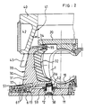
- Les figures 1, 2, 3 et 3' montrent le moule de l'invention au cours de la fermeture ;
- Les figures 4 et 4' montrent le moule de l'invention lors de la fermeture ;
- Les figures 5, 5' et 6 montrent le moule de l'invention au cours de l'ouverture ;
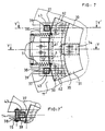
- Les figures 7 et 7' montrent une coupe partielle perpendiculaire à l'axe du moule ;
- La figure 7 est une coupe selon XX à la figure 4 ;
- La figure 7' est une coupe selon X'X' à la figure 4 ;
- Les figures 1, 2 et 6 sont des coupes selon YY à la figure 7 ;
- Les figures 3, 4 et 5 sont des coupes selon Y'Y' à la figure 7.
- Figures 1, 2, 3 and 3 'show the mold of the invention during closing;
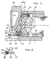
- Figures 4 and 4 'show the mold of the invention during closing;
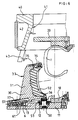
- Figures 5, 5 'and 6 show the mold of the invention during opening;
- Figures 7 and 7 'show a partial section perpendicular to the axis of the mold;
- Figure 7 is a section along XX in Figure 4;
- Figure 7 'is a section along X'X' in Figure 4;
- Figures 1, 2 and 6 are sections along YY in Figure 7;
- Figures 3, 4 and 5 are sections along Y'Y 'in Figure 7.
On aperçoit aux différentes figures la partie moulante inférieure 10 rendue solidaire du plateau inférieur 11, la partie moulante supérieure 20, un secteur 30 de la série de secteurs assurant le moulage de la bande de roulement. Ce secteur 30 est constitué d'une partie support 31, et d'une partie 32 assurant le moulage de la bande de roulement. Le secteur 30 présente une face 33 tronconique inclinée d'un angle α. Des plaquettes de glissement 34 sont vissées sur l'extrémité supérieure 35 de secteur 30, pour favoriser le glissement du secteur 30 le long de la partie moulante supérieure 20, et aussi pour limiter l'usure que pourrait provoquer le contact entre secteur 30 et partie moulante supérieure 20 survenant dans la cinématique de fermeture du moule.We can see in the different figures the
La couronne périphérique 40 comporte une face 41 radialement intérieure tronconique, dont l'inclinaison est identique à l'inclinaison α de la face 33 des secteurs 30. La cavité intérieure 42 permet la circulation d'un fluide caloporteur pour effectuer la vulcanisation.The
Les secteurs 30 sont sollicités en permanence par des ressorts 50, 51, en basculement et en recul radial. Chaque ressort 50 est disposé dans un évidement 12 prévu dans le plateau inférieur 11. Chaque ressort 50 tend à repousser vers le haut un poussoir 52 dont la course est limitée par une butée 53 fixée sur le plateau inférieur 11.The
Le poussoir 52 agit sur la partie inférieure 36 du secteur 30, à l'extrémité radialement intérieure de celui-ci. Les ressorts 51 de traction tendent en permanence à reculer les secteurs 30 vers leur position d'ouverture, et ce recul radial est limité par la couronne 40, ainsi que par l'axe 6 solidaire de chaque secteur 30. La partie centrale 61 de l'axe 6 peut glisser dans une boutonnière 13 délimitant le débattement radial autorisé pour l'axe 6.The
Chaque secteur 30 comporte deux plaques 37 rapportées par vissage en partie inférieure 36. Les pions de cisaillement 62 assurent la transmission des forces des plaques 37 aux secteurs 30. Chaque plaque 37 forme une protubérance 30 horizontale se développant radialement au-delà de la face 33 inclinée formant le dos de chaque secteur 30. Un logement 39 est percé au travers de chaque plaque 37, au niveau de ladite protubérance 38. Au droit de chaque logement, la couronne 40 comporte une tige 43 inclinée s'étendant axialement vers le bas par rapport à la couronne 40.Each
Le fonctionnement du moule est le suivant. Après avoir introduit le pneumatique l à vulcaniser, la partie moulante supérieure 20 et la couronne 40 sont abaissées selon la procédure habituelle pour ce type de moule. Les moyens spécifiques de la présente invention, à savoir les plaques 37 et les tiges 43, n'ont pas à intervenir pour assurer la fermeture dit moule. On aperçoit à la figure 3 que les tiges 43 peuvent librement pénétrer dans les logements 39 sans entrer en contact avec les plaques 37. La figure 4 montre le moule totalement fermé : il subsiste un jeu radial J entre le côté radialement extérieur de chaque tige, et le bord correspondant 16 du logement 39. Pour ouvrir le moule, il faut d'abord, tout en maintenant immobile le plateau supérieur (donc la partie moulante supérieure 20) relever la couronne 40. On aperçoit à la figure 5 que la couronne 40 libère les secteurs 30, les tiges 43 viennent en contact avec les bords 16 des logements 39, et le jeu J est reporté entre couronne 40 et secteurs 30. L'action des ressorts de tractions 51 est insuffisante pour décoller des secteurs 30 du pneumatique vulcanisé et ceux-ci restent donc à leur position de fermeture, le basculemnt sous l'action des ressorts 50 étant rendu impossible par la présence de la partie moulante supérieure 20 encore en contact avec les secteurs 30.The operation of the mold is as follows. After having introduced the
En continuant le mouvement d'élévation de la couronne 40, les tiges 43 provoquent une traction sur les secteurs 30 et forcent donc le mouvement de recul purement radial favorable au bon démoulage de la sculpture de la bande de roulement, sans provoquer de défauts sur celle-ci. De préférence, l'inclinaison β que font les tiges 43 est inférieure à l'inclinaison α des faces tronconiques 41 et 33, ce qui, ajouté au jeu J, empêche tout coincement à l'ouverture, et empêche toute collision entre pièces à la fermeture.Continuing the elevation movement of the
Les figures 3' 4', 5' et 7' représentent une variante d'exécution des plaques 37. On remplace le frotttement de glissement des tiges 43 sur le bord 16 par un frottement de roulement. A cette fin, on utilise un galet d'usure 14 monté mobile en rotation sur un axe 15 disposé à l'extrémité des plaques 37 et fermant le logement 39. Cette variante permet un ajustement du jeu J en jouant sur le diamètre du galet d'usure 14.Figures 3 '4', 5 'and 7' show an alternative embodiment of the
Dès que la sculpture est démoulée, il n'est plus nécessaire que le recul soit purement radial. On peut relever la partie moulante supérieure 20 et la suite du mouvement d'ouverture des secteurs est assurée, comme connu, par des ressorts 50 et 51.Once the sculpture is unmolded, it is no longer necessary for the recoil to be purely radial. The
Outre le fait qu'elle permet d'assurer un recul purement radial lors du démoulage, combiné avec un basculement ultérieur des secteurs 30, l'invention n'impose qu' un minimum de modifications aux moules connus et permet donc d'assurer un gain important en qualité des pneumatiques moulés avec un minimum d'investissement. En outre, la commande du recul radial ne requiert pas une grande précision d'usinage et/ou de montage, ce qui constitue encore un avantage de la présente invention.Besides the fact that it makes it possible to ensure a purely radial recoil during demolding, combined with a subsequent tilting of the
Claims (5)
- A sector mold (30) for the molding and vulcanizing of tires, of the type comprising a lower molding-part (10) for the molding of one sidewall of the tire, an upper molding part (20) for the molding of the other sidewall, and a series of sectors (30) for the molding of the tread, as well as a ring (40) for the closing and hooping of the series of sectors (30), the ring (40) comprising an inclined face (41), the opening and closing movements involving a radial recoil of the sectors (30) and a swinging upward of the sectors (30) towards the outside, as well as a lifting of the upper part (20), the radially outer face (33) of each sector (30) being inclined so as to cooperate with the complementary inclined face (41) of said ring (40), the ring (40) being adapted to be raised and lowered separately from the upper molding part (20), each sector (30) being continuously urged towards the recoiled and swung position by one or more springs, characterized by the fact that each sector (30) is provided with at least one horizontal protuberance (38) which extends radially beyond said inclined face (33), each protuberance being pierced by a recess (39), and by the fact that the ring (40) comprises, in correspondence with each recess (39), an inclined rod (43) which is arranged in such a manner as to be capable of penetrating into the recess (39) upon the closing of the mold and is intended to cooperate with the said protuberance (38) in order to cause the radial recoil of the sectors (30) upon the opening of the mold.
- A mold according to Claim 1, characterized by the fact that, in closed position, there is radial clearance (J) between the radially outer side of each rod (43) and the corresponding edge (16) of its recess (39).
- A mold according to Claim 1 or 2, characterized by the fact that, the said radially outer face (33) of each sector (30) being inclined by an angle α with respect to the axis of the mold, each rod (43) is inclined by an angle β which is slightly smaller than α.
- A mold according to any of Claims 1 to 3, characterized by the fact that the protuberances (38) are formed by at least one plate (37) attached to the lower part (36) of each sector (30), said recess (39) being pierced through each plate (37).
- A mold according to Claim 4, characterized by the fact that a roller (14) is mounted movably in rotation on a pin (15) which is arranged on the end of the said plates (37) and closing the said recess (39).
Priority Applications (1)
| Application Number | Priority Date | Filing Date | Title |
|---|---|---|---|
| AT91105202T ATE103856T1 (en) | 1990-04-19 | 1991-04-02 | FORM WITH PIVOTABLE AND RADIALLY MOVABLE SEGMENTS. |
Applications Claiming Priority (2)
| Application Number | Priority Date | Filing Date | Title |
|---|---|---|---|
| FR9005106A FR2661129B1 (en) | 1990-04-19 | 1990-04-19 | RADIAL BACKSIDE SECTOR MOLDS COMBINED WITH TIPPING. |
| FR9005106 | 1990-04-19 |
Publications (2)
| Publication Number | Publication Date |
|---|---|
| EP0452730A1 EP0452730A1 (en) | 1991-10-23 |
| EP0452730B1 true EP0452730B1 (en) | 1994-04-06 |
Family
ID=9395962
Family Applications (1)
| Application Number | Title | Priority Date | Filing Date |
|---|---|---|---|
| EP91105202A Expired - Lifetime EP0452730B1 (en) | 1990-04-19 | 1991-04-02 | Mould with pivoting, radially opening segments |
Country Status (6)
| Country | Link |
|---|---|
| US (1) | US5141424A (en) |
| EP (1) | EP0452730B1 (en) |
| JP (1) | JP2977931B2 (en) |
| AT (1) | ATE103856T1 (en) |
| DE (1) | DE69101577T2 (en) |
| FR (1) | FR2661129B1 (en) |
Families Citing this family (19)
| Publication number | Priority date | Publication date | Assignee | Title |
|---|---|---|---|---|
| US5585064A (en) * | 1994-07-20 | 1996-12-17 | The Goodyear Tire & Rubber Company | Ventless segmented tire mold and method therefore |
| US5637110A (en) * | 1995-01-31 | 1997-06-10 | Stryker Corporation | Electrocautery surgical tool with relatively pivoted tissue engaging jaws |
| US6290810B1 (en) * | 1995-06-30 | 2001-09-18 | The Goodyear Tire & Rubber Company | Mold for curing precured treads to tire casings |
| US5939002A (en) * | 1997-04-16 | 1999-08-17 | Michelin Recherche Et Technique S.A. | Apparatus and process for changing a sidewall insert of a tire mold |
| JP3874507B2 (en) * | 1997-10-09 | 2007-01-31 | 株式会社ブリヂストン | Tire vulcanizer |
| AU1187199A (en) * | 1998-10-09 | 2000-05-01 | Goodyear Tire And Rubber Company, The | Method and apparatus for molding a tire |
| US6808377B1 (en) | 1999-10-01 | 2004-10-26 | The Goodyear Tire & Rubber Company | Segmented tire mold |
| JP2002166424A (en) * | 2000-11-29 | 2002-06-11 | Bridgestone Corp | Method for vulcanizing pneumatic tire and mold used for the method |
| ATE340691T1 (en) * | 2001-02-20 | 2006-10-15 | Michelin Soc Tech | MOLDING TOOL AND METHOD FOR SHAPING A TIRE TREAD |
| US6632393B2 (en) | 2001-09-06 | 2003-10-14 | Louis T. Fike | Method and apparatus for curing radial tires |
| JP3853211B2 (en) * | 2001-12-28 | 2006-12-06 | 株式会社ブリヂストン | Tire vulcanizing method and apparatus |
| US6716013B2 (en) * | 2002-01-25 | 2004-04-06 | Louis T. Fike | Tear resistant shield for a tread segment of a segmented tire mold |
| US20040260337A1 (en) | 2003-06-18 | 2004-12-23 | Scimed Life Systems, Inc. | Endoscopic instruments and methods of manufacture |
| US8469993B2 (en) | 2003-06-18 | 2013-06-25 | Boston Scientific Scimed, Inc. | Endoscopic instruments |
| JP2006312251A (en) * | 2005-05-06 | 2006-11-16 | Bridgestone Corp | Tire vulcanizer |
| FR2998830B1 (en) * | 2012-12-04 | 2015-02-20 | Michelin & Cie | COOKING MOLD OF PNEUMATIC ENVELOPE BRAKE INCLUDING MOBILE SECTORS |
| FR3020983B1 (en) * | 2014-05-14 | 2016-06-24 | Michelin & Cie | PNEUMATIC COOKING MOLD COMPRISING RESISTANT SECTORS SUPPORTING A PLURALITY OF CIRCONFERENTIALLY MOBILE MOLDING SECTIONS |
| FR3024074B1 (en) * | 2014-07-25 | 2016-09-02 | Michelin & Cie | VULCANIZATION MOLD FOR OPTIMIZED CLOSURE PNEUMATIC |
| JP7064423B2 (en) * | 2018-10-16 | 2022-05-10 | 株式会社ブリヂストン | Tire vulcanizer |
Family Cites Families (8)
| Publication number | Priority date | Publication date | Assignee | Title |
|---|---|---|---|---|
| DE1729619B2 (en) * | 1966-04-19 | 1976-04-15 | Dunlop Holdings Ltd., London | VULCANIZING FORMS FOR A PNEUMATIC TIRE |
| FR1590815A (en) * | 1968-11-06 | 1970-04-20 | ||
| US3922122A (en) * | 1971-12-17 | 1975-11-25 | Pirelli | Apparatus for molding an embossed pattern on the peripheral band of a toroidal article, in particular on tire treads |
| GB1473649A (en) * | 1973-07-12 | 1977-05-18 | Dunlop Ltd | Tyre moulds |
| FR2270088B1 (en) * | 1974-03-29 | 1977-01-07 | ||
| FR2342153A1 (en) * | 1976-02-24 | 1977-09-23 | Kleber Colombes | SECTOR MOLD |
| IT1176523B (en) * | 1984-08-01 | 1987-08-18 | Pirelli | IMPROVEMENTS IN THE VULCANIZATION PRESSES |
| HUT49071A (en) * | 1987-12-16 | 1989-08-28 | Taurus Gumiipari Vallalat | Mould carrying and actuating device for vulcanizing radial tyres |
-
1990
- 1990-04-19 FR FR9005106A patent/FR2661129B1/en not_active Expired - Fee Related
-
1991
- 1991-04-02 AT AT91105202T patent/ATE103856T1/en not_active IP Right Cessation
- 1991-04-02 EP EP91105202A patent/EP0452730B1/en not_active Expired - Lifetime
- 1991-04-02 DE DE69101577T patent/DE69101577T2/en not_active Expired - Fee Related
- 1991-04-04 US US07/680,395 patent/US5141424A/en not_active Expired - Lifetime
- 1991-04-18 JP JP3086496A patent/JP2977931B2/en not_active Expired - Fee Related
Also Published As
| Publication number | Publication date |
|---|---|
| ATE103856T1 (en) | 1994-04-15 |
| EP0452730A1 (en) | 1991-10-23 |
| DE69101577D1 (en) | 1994-05-11 |
| DE69101577T2 (en) | 1994-08-25 |
| FR2661129B1 (en) | 1992-07-10 |
| JP2977931B2 (en) | 1999-11-15 |
| JPH0592431A (en) | 1993-04-16 |
| US5141424A (en) | 1992-08-25 |
| FR2661129A1 (en) | 1991-10-25 |
Similar Documents
| Publication | Publication Date | Title |
|---|---|---|
| EP0452730B1 (en) | Mould with pivoting, radially opening segments | |
| EP2448750B1 (en) | Sector mold with radial regression | |
| LU86192A1 (en) | MOLD FOR PNEUMATIC TIRES | |
| FR2715119A1 (en) | Improved autoguiding arm of a road vehicle along a steering rail. | |
| EP1417082B1 (en) | Mould for tyre running tread | |
| CA2033521C (en) | Self-locking sectional mold for the vulcanization of tire casings | |
| EP3386704B1 (en) | Curing press for a tyre blank, comprising a tie rod | |
| FR2577760A1 (en) | Method for making edible containers in the form of cups or the like from biscuit dough and device for carrying out said method | |
| EP2897790B1 (en) | Vulcanizing device with radially mobile segments for a tyre | |
| EP2928677B1 (en) | Tyre curing mould comprising movable sectors. | |
| EP2072204B1 (en) | Mould for vulcanisation of a raw blank of a tyre | |
| EP3386741B1 (en) | Curing press for a tyre blank | |
| EP0437413B1 (en) | Removable unitary structure for securing and supporting a road vehicle by its wheels | |
| EP0738578B1 (en) | Method and mould for injection moulding a glass of an illumination or signalling device of a vehicle | |
| WO2020126798A1 (en) | Mold with sectors for tires, in particular tires for agricultural vehicles, and associated molding method | |
| WO2024028139A1 (en) | Curing mould and method for curing a green tyre | |
| FR3071189B1 (en) | COOKING PRESS OF A PNEUMATIC BRAKE | |
| FR2705611A1 (en) | Moulding press with rotary (bed)plate | |
| WO2014086880A1 (en) | Tyre vulcanizing mould | |
| BE862573A (en) | APPARATUS FOR MAKING A WHEEL RIM | |
| BE642417A (en) | ||
| WO2014086879A1 (en) | Tyre vulcanizing mould | |
| BE555903A (en) |
Legal Events
| Date | Code | Title | Description |
|---|---|---|---|
| PUAI | Public reference made under article 153(3) epc to a published international application that has entered the european phase |
Free format text: ORIGINAL CODE: 0009012 |
|
| 17P | Request for examination filed |
Effective date: 19910403 |
|
| AK | Designated contracting states |
Kind code of ref document: A1 Designated state(s): AT BE CH DE DK ES FR GB GR IT LI LU NL SE |
|
| 17Q | First examination report despatched |
Effective date: 19930622 |
|
| GRAA | (expected) grant |
Free format text: ORIGINAL CODE: 0009210 |
|
| AK | Designated contracting states |
Kind code of ref document: B1 Designated state(s): AT BE CH DE DK ES FR GB GR IT LI LU NL SE |
|
| PG25 | Lapsed in a contracting state [announced via postgrant information from national office to epo] |
Ref country code: GR Free format text: LAPSE BECAUSE OF FAILURE TO SUBMIT A TRANSLATION OF THE DESCRIPTION OR TO PAY THE FEE WITHIN THE PRESCRIBED TIME-LIMIT Effective date: 19940406 Ref country code: GB Effective date: 19940406 Ref country code: SE Free format text: THE PATENT HAS BEEN ANNULLED BY A DECISION OF A NATIONAL AUTHORITY Effective date: 19940406 Ref country code: DK Effective date: 19940406 Ref country code: NL Effective date: 19940406 Ref country code: ES Free format text: THE PATENT HAS BEEN ANNULLED BY A DECISION OF A NATIONAL AUTHORITY Effective date: 19940406 |
|
| REF | Corresponds to: |
Ref document number: 103856 Country of ref document: AT Date of ref document: 19940415 Kind code of ref document: T |
|
| REF | Corresponds to: |
Ref document number: 69101577 Country of ref document: DE Date of ref document: 19940511 |
|
| ITF | It: translation for a ep patent filed |
Owner name: JACOBACCI CASETTA & PERANI S.P.A. |
|
| NLV1 | Nl: lapsed or annulled due to failure to fulfill the requirements of art. 29p and 29m of the patents act | ||
| GBV | Gb: ep patent (uk) treated as always having been void in accordance with gb section 77(7)/1977 [no translation filed] |
Effective date: 19940406 |
|
| PLBE | No opposition filed within time limit |
Free format text: ORIGINAL CODE: 0009261 |
|
| STAA | Information on the status of an ep patent application or granted ep patent |
Free format text: STATUS: NO OPPOSITION FILED WITHIN TIME LIMIT |
|
| 26N | No opposition filed | ||
| PG25 | Lapsed in a contracting state [announced via postgrant information from national office to epo] |
Ref country code: LI Effective date: 19950430 Ref country code: CH Effective date: 19950430 |
|
| REG | Reference to a national code |
Ref country code: CH Ref legal event code: PL |
|
| PGFP | Annual fee paid to national office [announced via postgrant information from national office to epo] |
Ref country code: AT Payment date: 20020328 Year of fee payment: 12 |
|
| PG25 | Lapsed in a contracting state [announced via postgrant information from national office to epo] |
Ref country code: AT Free format text: LAPSE BECAUSE OF NON-PAYMENT OF DUE FEES Effective date: 20030402 |
|
| PGFP | Annual fee paid to national office [announced via postgrant information from national office to epo] |
Ref country code: LU Payment date: 20070412 Year of fee payment: 17 |
|
| PGFP | Annual fee paid to national office [announced via postgrant information from national office to epo] |
Ref country code: BE Payment date: 20070502 Year of fee payment: 17 |
|
| BERE | Be: lapsed |
Owner name: PNEUMATIQUES *KLEBER Effective date: 20080430 |
|
| PG25 | Lapsed in a contracting state [announced via postgrant information from national office to epo] |
Ref country code: BE Free format text: LAPSE BECAUSE OF NON-PAYMENT OF DUE FEES Effective date: 20080430 |
|
| PGFP | Annual fee paid to national office [announced via postgrant information from national office to epo] |
Ref country code: IT Payment date: 20090428 Year of fee payment: 19 Ref country code: FR Payment date: 20090414 Year of fee payment: 19 Ref country code: DE Payment date: 20090422 Year of fee payment: 19 |
|
| PG25 | Lapsed in a contracting state [announced via postgrant information from national office to epo] |
Ref country code: LU Free format text: LAPSE BECAUSE OF NON-PAYMENT OF DUE FEES Effective date: 20080402 |
|
| REG | Reference to a national code |
Ref country code: FR Ref legal event code: ST Effective date: 20101230 |
|
| PG25 | Lapsed in a contracting state [announced via postgrant information from national office to epo] |
Ref country code: DE Free format text: LAPSE BECAUSE OF NON-PAYMENT OF DUE FEES Effective date: 20101103 |
|
| PG25 | Lapsed in a contracting state [announced via postgrant information from national office to epo] |
Ref country code: IT Free format text: LAPSE BECAUSE OF NON-PAYMENT OF DUE FEES Effective date: 20100402 |
|
| PG25 | Lapsed in a contracting state [announced via postgrant information from national office to epo] |
Ref country code: FR Free format text: LAPSE BECAUSE OF NON-PAYMENT OF DUE FEES Effective date: 20100430 |