EP2928677B1 - Tyre curing mould comprising movable sectors. - Google Patents
Tyre curing mould comprising movable sectors. Download PDFInfo
- Publication number
- EP2928677B1 EP2928677B1 EP13808147.6A EP13808147A EP2928677B1 EP 2928677 B1 EP2928677 B1 EP 2928677B1 EP 13808147 A EP13808147 A EP 13808147A EP 2928677 B1 EP2928677 B1 EP 2928677B1
- Authority
- EP
- European Patent Office
- Prior art keywords
- shell
- axis
- lever
- ramp
- mould according
- Prior art date
- Legal status (The legal status is an assumption and is not a legal conclusion. Google has not performed a legal analysis and makes no representation as to the accuracy of the status listed.)
- Active
Links
- 230000005484 gravity Effects 0.000 claims description 6
- 230000000694 effects Effects 0.000 claims description 5
- 238000004519 manufacturing process Methods 0.000 claims description 4
- 238000000034 method Methods 0.000 claims description 2
- 230000000670 limiting effect Effects 0.000 description 5
- 238000000926 separation method Methods 0.000 description 5
- 238000000605 extraction Methods 0.000 description 4
- 238000005096 rolling process Methods 0.000 description 4
- 238000010411 cooking Methods 0.000 description 2
- 238000000465 moulding Methods 0.000 description 2
- 229910000906 Bronze Inorganic materials 0.000 description 1
- 230000005540 biological transmission Effects 0.000 description 1
- 239000010974 bronze Substances 0.000 description 1
- KUNSUQLRTQLHQQ-UHFFFAOYSA-N copper tin Chemical compound [Cu].[Sn] KUNSUQLRTQLHQQ-UHFFFAOYSA-N 0.000 description 1
- 230000001419 dependent effect Effects 0.000 description 1
- 238000006073 displacement reaction Methods 0.000 description 1
- 229940082150 encore Drugs 0.000 description 1
- 238000009434 installation Methods 0.000 description 1
- 239000000463 material Substances 0.000 description 1
- 230000036961 partial effect Effects 0.000 description 1
- -1 polytetrafluoroethylene ring Polymers 0.000 description 1
- 230000002829 reductive effect Effects 0.000 description 1
- 230000000284 resting effect Effects 0.000 description 1
- 230000000717 retained effect Effects 0.000 description 1
- 239000011435 rock Substances 0.000 description 1
- 238000007493 shaping process Methods 0.000 description 1
Images


Classifications
-
- B—PERFORMING OPERATIONS; TRANSPORTING
- B29—WORKING OF PLASTICS; WORKING OF SUBSTANCES IN A PLASTIC STATE IN GENERAL
- B29D—PRODUCING PARTICULAR ARTICLES FROM PLASTICS OR FROM SUBSTANCES IN A PLASTIC STATE
- B29D30/00—Producing pneumatic or solid tyres or parts thereof
- B29D30/06—Pneumatic tyres or parts thereof (e.g. produced by casting, moulding, compression moulding, injection moulding, centrifugal casting)
- B29D30/0601—Vulcanising tyres; Vulcanising presses for tyres
- B29D30/0606—Vulcanising moulds not integral with vulcanising presses
- B29D30/0629—Vulcanising moulds not integral with vulcanising presses with radially movable sectors
-
- B—PERFORMING OPERATIONS; TRANSPORTING
- B29—WORKING OF PLASTICS; WORKING OF SUBSTANCES IN A PLASTIC STATE IN GENERAL
- B29C—SHAPING OR JOINING OF PLASTICS; SHAPING OF MATERIAL IN A PLASTIC STATE, NOT OTHERWISE PROVIDED FOR; AFTER-TREATMENT OF THE SHAPED PRODUCTS, e.g. REPAIRING
- B29C33/00—Moulds or cores; Details thereof or accessories therefor
- B29C33/20—Opening, closing or clamping
- B29C33/26—Opening, closing or clamping by pivotal movement
Definitions
- the invention relates to the manufacture of tire casings and in particular the baking molds of the blank of the casing. Molds for baking a tire casing blank having circumferentially distributed movable sectors for molding the tread of the casing are well known.
- each sector is associated with a lever articulated to the sector, connected to the mold frame and resting on a ramp of the shell forming a face oriented in the direction of the axis.
- the mechanism described in this document has the disadvantage of not allowing full tilting of the sectors during the opening, which may be useful to facilitate tire extraction maneuvers at the end of the cooking cycle.
- This mechanism requires the production of significant efforts to separate the sectors with respect to the envelope, particularly when the envelope has on its tread aggressive sculptures that make this separation more difficult. As a result, the mechanism is relatively bulky, which increases the volume of the installation.
- An object of the invention is to control and accompany the rear tilting of the sectors during the final phase of the opening of the mold.
- this orientation of the ramp allows, by continuing the upward movement of the shell, to tilt the sector radially outwardly. Tipping gives better access to the envelope once the mold is open. It facilitates the extraction of the envelope and the establishment of a blank to cook. This arrangement also reduces the volume occupied by the mechanism. And the latter remains able to make significant efforts to separate the sectors of the envelope.
- the mold is arranged such that the shell moves the sector to a point from which the lever is no longer connected to the shell regardless of the sector.
- the shell cooperates directly with the sector, the lever serving only to transmit the forces at the beginning of the movement for the separation of the sectors relative to the envelope.
- the lever carries a roller capable of rolling on the ramp.
- This roller which forms a wear part, cash a large part of efforts and facilitates their transmission.
- the mold is arranged so that the shell moves the sector to a point from which the roller is no longer in contact with the shell.
- the mold is arranged so that an axial sliding of the shell towards the frame, combined with the effect of gravity, causes a tilting of the sector radially inwards.
- the aforementioned distance of sectors does not generate additional maneuver for the operator. Indeed, it is the movement of the shell itself, combined with the effect of gravity, which then places the sectors in the right position for the next cycle.
- the mold is arranged so that the sector comes into contact with a face of the shell which is inclined with respect to a plane perpendicular to the axis and in a direction opposite to the axis, the angle of the face by ratio to the plane being preferably between 0 ° and 5 °.
- the lever is hinged to the sector around an axis slidably mounted in a housing sector.
- the mold comprises stop means capable of limiting rotation of the sector relative to the lever in the direction opposite to the axis.
- the lever is mounted so as to be solely rotatable relative to the frame.
- the mold comprises an abutment adapted to limit a rotation of the lever relative to the frame in the direction opposite to the axis.
- the ramp has a non-rectilinear profile.
- the ramp has an inclination relative to the stronger axis in a section corresponding to the end of the movement of removal in a corresponding section at the beginning of this movement.
- the ramp has a curved profile portion having a center of curvature located on one side of the ramp opposite the axis.
- the ramp has a portion with a straight profile.
- the lever has an extension capable of extending under the shell.
- This extension also allows to limit the rotation of the lever relative to the shell and also to tilt the sector in the direction of the axis when the shell slides to close the mold.
- a method of manufacturing a tire casing as defined in claim 15, wherein a method according to the invention is used.
- a mold according to a first embodiment of the invention. It is a mold for cooking and shaping wheel tire casing blanks. It may be a vehicle wheel such as a commercial vehicle, a passenger vehicle and a truck-type vehicle or a civil engineering machine.
- the mold 2 is generally of the type described in the document WO 2011/001095 presented above. For more details on the constitution of the mold and its operation, we can refer to this document which is here incorporated by reference.
- the mold comprises a frame 4, a plate 6 rigidly secured to a lower shell 8, a plate rigidly secured to an upper shell which have not been illustrated and lateral sectors 10. Only one of them has been illustrated in the figures.
- the sectors are arranged to be the image of each other by a rotation around the vertical main axis 12 of the mold.
- the two shells are slidably mounted relative to the frame, independently of each other, in the direction of the axis 12. They serve to mold the respective sides of the tire while the sectors 10 serve to mold the strip of rolling with the sculptures.
- the two shells form with the sectors a closed chamber in which the raw gum blank is received to be vulcanized and shaped.
- the two shells move away from each other in the direction of the axis 12 while the sectors move away from this axis in the radial direction. The movements in the opposite direction take place for the closure of the mold.
- Each sector 10 is associated with a part such as a sole 14 rigidly secured to the frame 4, and a lever 16 also called rocker or horn. So there are as many soles and levers as there are sectors.
- the lever 16 forms a rigid assembly articulated to the sole 14 about an axis 18. The rotation around this axis is the only movement of the lever that is allowed relative to the sole.
- the lever 16 carries a shaft 20 articulated to the lever about an axis 22, this shaft being moreover movably mounted in a groove, housing or opening 24 of the sector.
- This groove has in this case an elongate rectilinear vertical shape parallel to the axis 12 so that it allows only vertical sliding of the shaft relative to the sector.
- the lever 16 is connected to the sector by means of a sliding pivot.
- the lever 16 also carries a shaft 26 hinged to the lever about an axis 28 and itself bearing a roller 30.
- the axes 18, 22 and 28 are parallel to each other and horizontal.
- the shell 8 carries a nose 32 rigidly secured to the shell and having a ramp 34.
- This ramp forms a face oriented in the opposite direction to the axis 12.
- This face is adapted to serve as a rolling track for the roller 30.
- the face is profiled, having an upper section 36 of rectilinear profile and a curved lower section 38 with a center of curvature located on one side of the opposite side to the axis 12.
- the two sections extend in continuity one with the other and together constitute the whole of the ramp 34.
- the local inclination of the ramp relative to the vertical direction and to the axis 12 is increasing as one moves away from this axis.
- the ramp 34 forms an edge 39 with a horizontal upper face 40 of the shell. This face is in surface contact with a horizontal lower face 42 of the sector and serves to guide the horizontal sliding movement of the sector in the radial direction.
- the sector 10 comprises an ear 44 rigidly fixed to the sector and which forms the connection of the lever with the sector by receiving the shaft 20.
- the lever 16 has two flat main faces parallel to a same radial plane to the axis 12.
- ear 44 extends on both sides of the lever 16, facing these two main faces, and comprises a junction 46 covering an outer face 48 of the lever facing away from the axis 12. This junction forms a stop capable of limiting the course of the sector 10 rotates relative to the lever 16 when it moves away from the axis 12, the junction 46 coming into contact with the face 48 at the end of this race.
- the sole 14 has a housing 50 receiving the lever 16 and a junction 52 extending facing the face 48 and also forming a stop capable of limiting the travel of the lever in rotation with respect to the sole when it moves away from the axis 12, the junction 52 coming into contact with the face 48.
- the figure 1 illustrates the closed configuration of the mold, the blank not being illustrated.
- the sectors 10 occupy their position closest to the axis 12 and are in surface contact with the lower shell by means of the faces 40, 42 and also in surface contact with the upper shell.
- the roller 30 is in contact with the upper end of the ramp 34 formed by the edge 39, or is very close to this ramp.
- the shaft 20 is at the upper end of the groove 24.
- each sector 10 is therefore also driven in translation in the vertical direction. It is the same for the draft. But this movement causes rolling 30 of the roller down on the rectilinear section 36 of the ramp. As this section is inclined, the lever 16 drives the ear and the sector in radial sliding relative to the shell 8 away from the axis 12. At the same time, the shaft 20 down into the groove 24.
- the shape of the ramp is adapted so that, in the reference of the shell, the sector has a purely radial rectilinear movement, so that the sculpture elements carried by the sector are extracted from the tread of the tire, which also follows the movement of the shell, according to a purely radial trajectory.
- the sliding up of the shell continues.
- the roller travels the rectilinear section 36 and the curved section 38.
- the sectors have separated from the tread so that the curved section can move the sector faster in the radial direction. But comes a moment when the shaft 20 reaches the lower end of the groove 24.
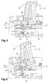
- the subsequent rise of the shell then causes the tilting of the sector in rotation radially outwards, the sector bearing on the edge 39 so that the face 42 is detached from the face 40. This tilting also removes the sector relative to the axis 12. It is observed that this tilting is allowed by the fact that the axis 22 is beyond the ramp with reference to the radial direction.
- An alternative embodiment consists in slightly tilting down the radially outer portion of the face 40 of the shell so as to promote the tilting of the sector.
- the angle of inclination ⁇ relative to the plane, perpendicular to the axis, of the shell, can usefully be between 0 ° and 5 °, as illustrated in FIG. figure 3 .
- the roller moves away from the ramp so that the lever 16 is no longer connected only to the sole 14 on the one hand and the ear 44 on the other hand.
- the junctions 46 and 52 define one end of the lever and sector tilting strokes, thus preventing these elements from moving too far from the axis 12.
- the rise of the shell is stopped before the shaft 22 reaches its end again.
- the mold is closed. For that, we do slide the lower shell 8 in the axial direction but this time down. During this movement, the sector that has remained supported on the edge 39 by gravity rocking with the lever 16 to move closer to the axis 12 until again make contact between the faces 40 and 42, as illustrated to the figure 8 .
- the position of the sector and the lever furthest from the axis is in fact defined with respect to the axes of rotation 18 and 22 so that the sector tends by gravity to approach the axis when the movement of the shell allows him.
- the roller 30 remains out of contact with the ramp and more generally with the shell.
- a hooping ring 54 is then slid downwards in the axial direction, which has a frustoconical internal face 56 adapted to cooperate with a frustoconical outer face 58 of the sectors so that the sliding of these faces one on the other causes the radial sliding of the sectors in the direction of the axis 12.
- the two frustoconical faces have the same radius and have the axis 12 for common axis.
- the mold is found in the configuration of the figure 1 .
- the mechanism for guiding the movement of the sectors is compact and reduces the risk of wear due to the friction of the parts. Thanks to this reduced size, such a mechanism can equip molds comprising up to twenty sectors or more. It makes it possible to reduce the forces to be produced for demolding the envelope, especially when the latter has aggressive carvings by allowing the sculpting elements to be unthreaded in a substantially radial direction with respect to the tire.
- the roller forms a wear part. It is his role to cash out the demolding efforts.
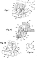
- a second embodiment of the mold has been illustrated at figure 10 .
- This embodiment differs from the previous one only in certain details.
- the main lies in an extension that has the lever 16 and here takes the form of a pallet 60 extending under the part of the shell carrying the ramp.
- the support of the shell on the pallet causes the tilting of the lever in the direction of the axis.
- the pallet also limits the tilting of the lever in the opposite direction when opening the mold.
- the ramp has a curved profile along its length.
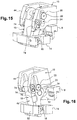
- Figures 11 to 16 a third embodiment of the mold according to the invention. It differs from the first mode only in certain details. Primarily, it aims to replace the stop 46 by the means that will be described below.
- each pin is rotatably mounted on the flank which carries it, the two pins having the same axis of rotation.
- the flanks have two respective faces facing one another.
- the pins extend projecting from the corresponding faces.
- Each pin comprises a shaft 72 ensuring its rotational mounting in the ear and a roller 74 in one piece with the shaft, rigidly fixed to the latter and extending projecting from the sidewall.
- the lever 16 has two flat lateral faces 75 parallel to each other and extending opposite the flanks of the ear respectively. Each of these faces is started from a median zone of the face to its rear edge to define a recess whose front edge forms a non-planar ramp 76 but whose generatrices are perpendicular to the face 75. Both ends of the ramp open into the rear edge of the face 75 and are curved.
- the rollers 74 of the pins are housed in the corresponding recesses so as to roll on the ramps 76.
- the opening of the mold begins as explained in the first embodiment.
- This embodiment of the stop is more robust and durable than that of the first mode, especially when the latter is made by a welded strip.
- This abutment effect can, moreover, be accentuated by giving a swollen shape to the upper end of the ramp, as illustrated in particular in FIGS. figures 13 and 15 .
- roller It is possible to equip the roller with a polytetrafluoroethylene ring, to make it in bronze or in another material.
Landscapes
- Engineering & Computer Science (AREA)
- Mechanical Engineering (AREA)
- Moulds For Moulding Plastics Or The Like (AREA)
- Heating, Cooling, Or Curing Plastics Or The Like In General (AREA)
Description
L'invention concerne la fabrication des enveloppes de pneumatiques et en particulier les moules de cuisson de l'ébauche de l'enveloppe. Des moules de cuisson d'une ébauche d'enveloppe de pneumatique comportant des secteurs mobiles répartis circonférentiellement et destinés à mouler la bande de roulement de l'enveloppe, sont bien connus.The invention relates to the manufacture of tire casings and in particular the baking molds of the blank of the casing. Molds for baking a tire casing blank having circumferentially distributed movable sectors for molding the tread of the casing are well known.
Dans le document
Dans le document
Dans le document
Dans le document
Dans le document
Le mécanisme décrit dans ce document présente l'inconvénient de ne pas autoriser le basculement complet des secteurs lors de l'ouverture, ce qui peut s'avérer utile pour faciliter les manoeuvres d'extraction du pneumatique en fin de cycle de cuisson. De plus, il arrive que, au début de l'éloignement des secteurs, ceux-ci soient retenus élastiquement par la gomme de l'enveloppe puis, au moment de la séparation, basculent brutalement vers l'arrière avec le levier. Il est alors nécessaire de faire basculer manuellement les secteurs en sens contraire pour les remettre en place, ce qui constitue une opération laborieuse qui augmentait les temps de cycle.The mechanism described in this document has the disadvantage of not allowing full tilting of the sectors during the opening, which may be useful to facilitate tire extraction maneuvers at the end of the cooking cycle. In addition, it happens that, at the beginning of the removal of the sectors, they are elastically retained by the eraser of the envelope and, at the moment of separation, rock suddenly backwards with the lever. It is then necessary to manually switch the sectors in the opposite direction to replace them, which is a laborious operation that increased the cycle times.
Ce mécanisme nécessite la production d'efforts importants pour séparer les secteurs à l'égard de l'enveloppe, en particulier lorsque l'enveloppe présente sur sa bande de roulement des sculptures agressives qui rendent cette séparation plus difficile. De ce fait, le mécanisme est relativement encombrant, ce qui augmente le volume de l'installation.This mechanism requires the production of significant efforts to separate the sectors with respect to the envelope, particularly when the envelope has on its tread aggressive sculptures that make this separation more difficult. As a result, the mechanism is relatively bulky, which increases the volume of the installation.
Un but de l'invention est de maîtriser et d'accompagner le basculement arrière des secteurs lors de la phase finale de l'ouverture du moule.An object of the invention is to control and accompany the rear tilting of the sectors during the final phase of the opening of the mold.
À cet effet, on prévoit selon l'invention un moule de cuisson d'une ébauche d'enveloppe de pneumatique, comme défini dans la revendication 1, le moule comportant,
- un bâti présentant un axe,
- au moins une coquille apte à mouler un flanc de l'enveloppe, mobile axialement et présentant une rampe formant une face orientée en direction opposée à l'axe,
- des secteurs répartis circonférentiellement et destinés à mouler une bande de roulement de l'enveloppe et
- pour au moins l'un des secteurs, un levier relié d'une part au secteur, d'autre part au bâti et apte à être relié d'autre part encore à la rampe de sorte qu'un mouvement axial d'éloignement de la coquille par rapport au bâti entraîne successivement un mouvement radial du secteur par rapport à la coquille puis un basculement du secteur radialement vers l'extérieur.
- a frame having an axis,
- at least one shell capable of molding a flank of the casing, axially movable and having a ramp forming a face oriented in the direction opposite to the axis,
- circumferentially distributed sectors intended to mold a tread of the envelope and
- for at least one of the sectors, a lever connected on the one hand to the sector, on the other hand to the frame and adapted to be further connected to the ramp so that an axial movement away from the shell relative to the frame successively causes a radial movement of the sector relative to the shell and a tilting of the sector radially outwardly.
Ainsi, cette orientation de la rampe permet, en poursuivant le mouvement de montée de la coquille, de faire basculer le secteur radialement vers l'extérieur. Le basculement donne un meilleur accès à l'enveloppe une fois le moule ouvert. Il facilite l'extraction de l'enveloppe puis la mise en place d'une ébauche à cuire. Ce montage permet également de réduire le volume occupé par le mécanisme. Et ce dernier demeure en mesure de produire des efforts importants pour séparer les secteurs de l'enveloppe.Thus, this orientation of the ramp allows, by continuing the upward movement of the shell, to tilt the sector radially outwardly. Tipping gives better access to the envelope once the mold is open. It facilitates the extraction of the envelope and the establishment of a blank to cook. This arrangement also reduces the volume occupied by the mechanism. And the latter remains able to make significant efforts to separate the sectors of the envelope.
Des formes préférentielles de l'invention sont définies dans les revendications dépendantes. Dans un mode de réalisation, le moule est agencé de sorte que la coquille déplace le secteur jusqu'à un point à partir duquel le levier n'est plus relié à la coquille indépendamment du secteur.Preferred forms of the invention are defined in the dependent claims. In one embodiment, the mold is arranged such that the shell moves the sector to a point from which the lever is no longer connected to the shell regardless of the sector.
On peut donc prévoir par exemple que, à un certain stade du mouvement, la coquille coopère directement avec le secteur, le levier ne servant qu'à transmettre les efforts au début du mouvement pour la séparation des secteurs par rapport à l'enveloppe.It can therefore be provided for example that, at a certain stage of the movement, the shell cooperates directly with the sector, the lever serving only to transmit the forces at the beginning of the movement for the separation of the sectors relative to the envelope.
De préférence, le levier porte un galet apte à rouler sur la rampe.Preferably, the lever carries a roller capable of rolling on the ramp.
Ce galet, qui forme une pièce d'usure, encaisse une grande partie des efforts et facilite leur transmission.This roller, which forms a wear part, cash a large part of efforts and facilitates their transmission.
Avantageusement, le moule est agencé de sorte que la coquille déplace le secteur jusqu'à un point à partir duquel le galet n'est plus en contact avec la coquille.Advantageously, the mold is arranged so that the shell moves the sector to a point from which the roller is no longer in contact with the shell.
On peut prévoir que le moule est agencé de sorte qu'un coulissement axial de la coquille en direction du bâti, combiné à l'effet de la gravité, entraîne un basculement du secteur radialement vers l'intérieur.It can be provided that the mold is arranged so that an axial sliding of the shell towards the frame, combined with the effect of gravity, causes a tilting of the sector radially inwards.
Ainsi, l'éloignement précité des secteurs n'engendre pas de manoeuvre supplémentaire pour l'opérateur. En effet, c'est le mouvement de la coquille elle-même, combiné à l'effet de la gravité, qui replace ensuite les secteurs dans la bonne position pour le cycle suivant.Thus, the aforementioned distance of sectors does not generate additional maneuver for the operator. Indeed, it is the movement of the shell itself, combined with the effect of gravity, which then places the sectors in the right position for the next cycle.
De préférence, le moule est agencé de sorte que le secteur vient en contact avec une face de la coquille qui est inclinée par rapport à un plan perpendiculaire à l'axe et en direction opposée à l'axe, l'angle de la face par rapport au plan étant compris de préférence entre 0° et 5°.Preferably, the mold is arranged so that the sector comes into contact with a face of the shell which is inclined with respect to a plane perpendicular to the axis and in a direction opposite to the axis, the angle of the face by ratio to the plane being preferably between 0 ° and 5 °.
Avantageusement, le levier est articulé au secteur autour d'un axe monté coulissant dans un logement du secteur.Advantageously, the lever is hinged to the sector around an axis slidably mounted in a housing sector.
De préférence, le moule comprend des moyens formant butée aptes à limiter une rotation du secteur par rapport au levier en direction opposée à l'axe.Preferably, the mold comprises stop means capable of limiting rotation of the sector relative to the lever in the direction opposite to the axis.
Avantageusement, le levier est monté de façon à être uniquement mobile à rotation par rapport au bâti.Advantageously, the lever is mounted so as to be solely rotatable relative to the frame.
De préférence, le moule comprend une butée apte à limiter une rotation du levier par rapport au bâti en direction opposée à l'axe.Preferably, the mold comprises an abutment adapted to limit a rotation of the lever relative to the frame in the direction opposite to the axis.
Grâce aux butées précitées, la rotation des secteurs vers l'arrière au-delà d'un certain angle est prohibée.Thanks to the abovementioned abutments, the rotation of the sectors towards the rear beyond a certain angle is prohibited.
On peut aussi prévoir que la rampe présente un profil non rectiligne.It is also possible that the ramp has a non-rectilinear profile.
Dans un mode de réalisation, la rampe présente une inclinaison par rapport à l'axe plus forte dans un tronçon correspondant à la fin du mouvement d'éloignement que dans un tronçon correspondant au début de ce mouvement.In one embodiment, the ramp has an inclination relative to the stronger axis in a section corresponding to the end of the movement of removal in a corresponding section at the beginning of this movement.
Ainsi, au début de l'éloignement des secteurs, on les sollicite avec une intensité relativement importante quitte à les éloigner de façon relativement lente. Il s'agit en effet au début de privilégier une bonne séparation des secteurs par rapport à l'enveloppe. Une fois cette séparation obtenue, on peut augmenter la vitesse d'éloignement.Thus, at the beginning of the remoteness of the sectors, they are solicited with a relatively high intensity, even if they are removed relatively slowly. It is indeed at the beginning to privilege a good separation of sectors compared to the envelope. Once this separation is obtained, the speed of removal can be increased.
Par exemple, la rampe présente une portion à profil courbe ayant un centre de courbure situé d'un côté de la rampe opposé à l'axe.For example, the ramp has a curved profile portion having a center of curvature located on one side of the ramp opposite the axis.
Avantageusement, la rampe présente une portion à profil rectiligne.Advantageously, the ramp has a portion with a straight profile.
Dans un mode de réalisation, le levier présente un prolongement apte à s'étendre sous la coquille.In one embodiment, the lever has an extension capable of extending under the shell.
Ce prolongement permet lui aussi de limiter la rotation du levier par rapport à la coquille et également de faire basculer le secteur en direction de l'axe lorsque la coquille coulisse pour la fermeture du moule.This extension also allows to limit the rotation of the lever relative to the shell and also to tilt the sector in the direction of the axis when the shell slides to close the mold.
On prévoit également selon l'invention un procédé de fabrication d'une enveloppe de pneumatique, comme défini dans la revendication 15, dans lequel procédé on utilise un moule selon l'invention.Also provided according to the invention a method of manufacturing a tire casing, as defined in claim 15, wherein a method according to the invention is used.
Nous allons présenter trois modes de réalisation du moule selon l'invention à titre d'exemples non limitatifs et à l'appui des dessins annexés sur lesquels :
- la
figure 1 est une vue partielle en coupe d'un moule selon un mode de réalisation de l'invention, montrant un secteur ; - la
figure 2 est une vue en perspective de la partie du moule illustrée à lafigure 1 ; - la
figure 3 est une vue à plus grande échelle d'une partie du moule de lafigure 1 ; - les
figure 4 à 9 sont des vues analogues à lafigure 1 illustrant des étapes du fonctionnement du moule ; - la
figure 10 est une vue analogue à lafigure 1 montrant un deuxième mode de réalisation du moule selon l'invention ; - les
figures 11 et 12 sont des vues analogues auxfigures 2 et3 illustrant un troisième mode de réalisation du moule ; - les
figures 13 et 14 illustrent certaines des pièces du moule de lafigure 11 ; et - les
figures 15 et 16 sont des vues analogues à lafigure 11 montrant deux étapes du fonctionnement du moule.
- the
figure 1 is a partial sectional view of a mold according to one embodiment of the invention, showing a sector; - the
figure 2 is a perspective view of the part of the mold illustrated infigure 1 ; - the
figure 3 is a larger-scale view of a portion of the mold of thefigure 1 ; - the
figure 4 to 9 are similar views to thefigure 1 illustrating steps of the operation of the mold; - the
figure 10 is a view similar to thefigure 1 showing a second embodiment of the mold according to the invention; - the
Figures 11 and 12 are views similar tofigures 2 and3 illustrating a third embodiment of the mold; - the
Figures 13 and 14 illustrate some of the mold parts of thefigure 11 ; and - the
Figures 15 and 16 are similar views to thefigure 11 showing two stages of mold operation.
Nous allons décrire en référence aux
Le moule 2 est globalement du type de celui décrit dans le document
Le moule comprend un bâti 4, un plateau 6 rigidement solidaire d'une coquille inférieure 8, un plateau rigidement solidaire d'une coquille supérieure qui n'ont pas été illustrés et des secteurs latéraux 10. Seul l'un d'eux a été illustré sur les figures. Les secteurs sont disposés de façon à être l'image les uns des autres par une rotation autour de l'axe principal vertical 12 du moule.The mold comprises a
Les deux coquilles sont montées coulissantes par rapport au bâti, indépendamment l'une de l'autre, suivant la direction de l'axe 12. Elles servent à mouler les flancs respectifs du pneumatique tandis que les secteurs 10 servent à en mouler la bande de roulement avec les sculptures. Lors de la cuisson de l'ébauche, les deux coquilles forment avec les secteurs une enceinte fermée dans laquelle l'ébauche de gomme crue est reçue pour être vulcanisée et mise en forme. Pour l'ouverture du moule, les deux coquilles s'éloignent l'une de l'autre suivant la direction de l'axe 12 tandis que les secteurs s'éloignent de cet axe en direction radiale. Les mouvements en sens inverse ont lieu pour la fermeture du moule.The two shells are slidably mounted relative to the frame, independently of each other, in the direction of the
À chaque secteur 10 est associée une pièce telle qu'une semelle 14 rigidement solidaire du bâti 4, ainsi qu'un levier 16 également appelé basculeur ou guignol. Il y a donc autant de semelles et de leviers que de secteurs. Le levier 16 forme un ensemble rigide articulé à la semelle 14 autour d'un axe 18. La rotation autour de cet axe est le seul mouvement du levier qui soit permis par rapport à la semelle.Each
Le levier 16 porte un arbre 20 articulé au levier autour d'un axe 22, cet arbre étant par ailleurs monté mobile dans une gorge, logement ou ouverture 24 du secteur. Cette gorge présente en l'espèce une forme allongée rectiligne verticale parallèle à l'axe 12 de sorte qu'elle n'autorise qu'un coulissement vertical de l'arbre par rapport au secteur. Le levier 16 est donc relié au secteur au moyen d'un pivot coulissant.The
Le levier 16 porte en outre un arbre 26 articulé au levier autour d'un axe 28 et portant lui-même un galet 30.The
Les axes 18, 22 et 28 sont parallèles entre eux et horizontaux.The
La coquille 8 porte un nez 32 rigidement solidaire de la coquille et présentant une rampe 34. Cette rampe forme une face orientée en direction opposée à l'axe 12. Cette face est apte à servir de piste de roulement pour le galet 30. La face est profilée, en présentant un tronçon supérieur 36 de profil rectiligne et un tronçon inférieur courbe 38 avec un centre de courbure situé d'un côté de la face opposé à l'axe 12. Les deux tronçons s'étendent en continuité l'un avec l'autre et constituent à eux deux l'intégralité de la rampe 34. L'inclinaison locale de la rampe par rapport à la direction verticale et à l'axe 12 va en augmentant à mesure qu'on s'éloigne de cet axe.The
La rampe 34 forme une arête 39 avec une face supérieure horizontale 40 de la coquille. Cette face est en contact surfacique avec une face inférieure horizontale 42 du secteur et permet de guider le mouvement de coulissement horizontal du secteur suivant la direction radiale.The
Le secteur 10 comprend une oreille 44 rigidement fixée au secteur et qui forme la liaison du levier avec le secteur en recevant l'arbre 20. Le levier 16 présente deux faces principales plates parallèles à un même plan radial à l'axe 12. L'oreille 44 s'étend des deux côtés du levier 16, en regard de ces deux faces principales, et comprend une jonction 46 recouvrant une face externe 48 du levier orientée en direction opposée à l'axe 12. Cette jonction forme une butée apte à limiter la course du secteur 10 en rotation par rapport au levier 16 lorsqu'il s'éloigne de l'axe 12, la jonction 46 venant en contact avec la face 48 à l'extrémité de cette course.The
De façon similaire, la semelle 14 présente un logement 50 recevant le levier 16 et une jonction 52 s'étendant en regard de la face 48 et formant elle aussi une butée apte à limiter la course du levier en rotation par rapport à la semelle lorsqu'il s'éloigne de l'axe 12, la jonction 52 venant en contact avec la face 48.Similarly, the sole 14 has a
Nous allons maintenant présenter le fonctionnement du moule en ce qui concerne le déplacement des secteurs 10. Nous ne présenterons pas ci-après les mouvements de la coquille supérieure qui se déplace vers le haut pour l'ouverture du moule puis vers le bas pour la fermeture.We will now present the operation of the mold with regard to the displacement of the
La
En référence à la
En référence à la
Une variante d'exécution consiste à incliner légèrement vers le bas la partie radialement externe de la face 40 de la coquille de manière à favoriser le basculement du secteur. L'angle d'inclinaison α par rapport au plan, perpendiculaire à l'axe, de la coquille, peut être utilement compris entre 0° et 5°, comme illustré à la
En référence à la
En référence à la
Une fois l'ébauche installée, on procède à la fermeture du moule. Pour cela, on fait coulisser la coquille inférieure 8 suivant la direction axiale mais cette fois vers le bas. Au cours de ce mouvement, le secteur qui est demeuré en appui sur l'arête 39 par gravité bascule avec le levier 16 pour se rapprocher de l'axe 12 jusqu'à réaliser de nouveau le contact entre les faces 40 et 42, comme illustré à la
En référence à la
On observe ici que, lorsque l'anneau de frettage 54 n'est pas encore engagé au dos des secteurs, les secteurs reposent sur la partie radialement externe de la face 40. Lorsque cette partie radialement externe présente une légère pente, comme cela a été indiqué ci-dessus, les secteurs sont alors légèrement inclinés radialement vers l'extérieur. Cette disposition a pour effet d'agrandir le passage au niveau de la partie supérieure des secteurs et de favoriser l'introduction d'un pneumatique.It is observed here that, when the hooping
Le mécanisme assurant le guidage du mouvement des secteurs est compact et réduit les risques d'usure due au frottement des pièces. Grâce à cet encombrement réduit, un tel mécanisme peut équiper des moules comprenant jusqu'à une vingtaine de secteurs voire plus. Il permet de réduire les efforts à produire pour le démoulage de l'enveloppe notamment lorsque celle-ci a des sculptures agressives en autorisant un déboitage des éléments de sculpture dans une direction essentiellement radiale par rapport au pneumatique.The mechanism for guiding the movement of the sectors is compact and reduces the risk of wear due to the friction of the parts. Thanks to this reduced size, such a mechanism can equip molds comprising up to twenty sectors or more. It makes it possible to reduce the forces to be produced for demolding the envelope, especially when the latter has aggressive carvings by allowing the sculpting elements to be unthreaded in a substantially radial direction with respect to the tire.
Le galet forme une pièce d'usure. C'est à lui que revient le rôle d'encaisser les efforts de démoulage.The roller forms a wear part. It is his role to cash out the demolding efforts.
On a illustré un deuxième mode de réalisation du moule à la
On a illustré aux
Les deux flancs de l'oreille 44 entre lesquels est reçu le levier 16 portent deux pions respectifs 70 illustrés à la
Le levier 16 présente deux faces latérales planes 75 parallèles entre elles et s'étendant en regard des flancs de l'oreille respectivement. Chacune de ces faces est entamée à partir d'une zone médiane de la face jusqu'à son bord arrière afin de définir un évidement dont le bord avant forme une rampe non plane 76 mais dont les génératrices sont perpendiculaires à la face 75. Les deux extrémités de la rampe débouchent dans le bord arrière de la face 75 et sont incurvées. Les galets 74 des pions sont logés dans les évidements correspondants de façon à rouler sur les rampes 76.The
On a illustré à la
L'ouverture du moule débute comme expliqué dans le premier mode de réalisation.The opening of the mold begins as explained in the first embodiment.
A mesure que la coquille 8 monte par rapport au bâti et que l'arbre 20 descend dans les gorges 24, les galets 74 roulent contre les rampes en direction du sommet de celles-ci.As the
Vient donc le moment où l'arbre 20 arrive à l'extrémité inférieure des gorges 24. A ce moment, les galets viennent en butée contre la zone d'extrémité supérieure incurvée des rampes. La coquille 8 tend à faire tourner le secteur 10 autour de l'axe 22 dans le sens contraire des aiguilles d'une montre sur la
Ce mode de réalisation de la butée est plus robuste et durable que celui du premier mode, notamment lorsque ce dernier est réalisé par une barrette soudée.This embodiment of the stop is more robust and durable than that of the first mode, especially when the latter is made by a welded strip.
Cet effet de butée peut d'ailleurs être accentué en donnant une forme renflée à l'extrémité supérieure de la rampe comme illustré notamment aux
Par ailleurs, le basculement du levier (et du secteur) par rapport à la semelle 14 est permis et se produit mais est finalement limité par la butée 52 comme précédemment.Furthermore, the tilting of the lever (and the sector) relative to the sole 14 is allowed and occurs but is ultimately limited by the
Bien entendu, on pourra apporter à l'invention de nombreuses modifications sans sortir du cadre de celle-ci.Of course, we can bring to the invention many changes without departing from the scope thereof.
On peut se dispenser de prévoir les fonctions limitant le basculement du levier et du secteur en direction opposée à l'axe.One can dispense with providing the functions limiting the tilting of the lever and the sector in the opposite direction to the axis.
On peut équiper le galet d'une bague en polytétrafluoroéthylène, le réaliser en bronze ou encore dans un autre matériau.It is possible to equip the roller with a polytetrafluoroethylene ring, to make it in bronze or in another material.
Claims (15)
- Mould (2) for curing a green tyre casing, which comprises:- a supporting structure (4) having an axis (12),- at least one shell (8) that is able to mould a sidewall of the casing, said shell being able to move axially and having a ramp (34) that forms a face oriented in the direction away from the axis,- segments (10) that are distributed circumferentially and are intended to mould a tread of the casing, and,- for at least one of the segments, a lever (16) that is connected on one side to the segment and on the other side to the supporting structure and is also able to be connected to the ramp such that an axial movement of the shell away from the supporting structure successively causes a radial movement of the segment with respect to the shell and then tilting of the segment radially towards the outside.
- Mould according to the preceding claim, wherein the lever bears a roller (30) that is able to roll on the ramp.
- Mould according to the preceding claim, which is designed such that the shell moves the segment as far as a point from which the roller (30) is no longer in contact with the shell.
- Mould according to at least any one of the preceding claims, which is designed such that axial sliding of the shell (8) in the direction of the supporting structure, combined with the effect of gravity, causes the segment to tilt radially towards the inside.
- Mould according to at least one of the preceding claims, which is designed such that the segment (10) comes into contact with a face (40) of the shell which is inclined with respect to a plane perpendicular to the axis (12) and in the direction away from the axis, the angle (α) of the face with respect to the plane being preferably between 0° and 5°.
- Mould according to at least any one of the preceding claims, wherein the lever is articulated to the segment about a spindle (22) mounted in a sliding manner in a housing in the segment.
- Mould according to at least any one of the preceding claims, which comprises means forming a stop (46; 74, 76) that are able to limit a rotation of the segment with respect to the lever in the direction away from the axis.
- Mould according to at least any one of the preceding claims, wherein the lever (16) is mounted so as to be only able to rotate with respect to the supporting structure.
- Mould according to at least any one of the preceding claims, which comprises a stop (52) that is able to limit a rotation of the lever with respect to the supporting structure in the direction away from the axis (12).
- Mould according to at least any one of the preceding claims, wherein the ramp (34) has a non-rectilinear profile.
- Mould according to at least any one of the preceding claims, wherein the ramp (34) has an inclination with respect to the axis that is greater in a section corresponding to the end of the movement apart than in a section corresponding to the start of this movement.
- Mould according to at least any one of the preceding claims, wherein the ramp has a portion (38) with a curved profile having a centre of curvature located on a side of the ramp away from the axis.
- Mould according to at least any one of the preceding claims, wherein the ramp has a portion (36) with a rectilinear profile.
- Mould according to at least any one of the preceding claims, wherein the lever has an extension (60) that is able to extend under the shell.
- Method for manufacturing a tyre casing, wherein use is made of a mould (2) according to at least any one of the preceding claims.
Applications Claiming Priority (2)
| Application Number | Priority Date | Filing Date | Title |
|---|---|---|---|
| FR1261607A FR2998830B1 (en) | 2012-12-04 | 2012-12-04 | COOKING MOLD OF PNEUMATIC ENVELOPE BRAKE INCLUDING MOBILE SECTORS |
| PCT/FR2013/052920 WO2014087089A1 (en) | 2012-12-04 | 2013-12-03 | Mould for curing a green tyre casing, comprising mobile segments |
Publications (2)
| Publication Number | Publication Date |
|---|---|
| EP2928677A1 EP2928677A1 (en) | 2015-10-14 |
| EP2928677B1 true EP2928677B1 (en) | 2017-07-19 |
Family
ID=47878217
Family Applications (1)
| Application Number | Title | Priority Date | Filing Date |
|---|---|---|---|
| EP13808147.6A Active EP2928677B1 (en) | 2012-12-04 | 2013-12-03 | Tyre curing mould comprising movable sectors. |
Country Status (3)
| Country | Link |
|---|---|
| EP (1) | EP2928677B1 (en) |
| FR (1) | FR2998830B1 (en) |
| WO (1) | WO2014087089A1 (en) |
Families Citing this family (4)
| Publication number | Priority date | Publication date | Assignee | Title |
|---|---|---|---|---|
| FR3044951B1 (en) | 2015-12-10 | 2018-01-26 | Compagnie Generale Des Etablissements Michelin | COOKING PRESS OF A PNEUMATIC BLANK COMPRISING A LINK |
| FR3044952B1 (en) * | 2015-12-10 | 2018-08-03 | Michelin & Cie | COOKING PRESS OF A PNEUMATIC BRAKE |
| GB201707031D0 (en) * | 2017-05-03 | 2017-06-14 | Baker Perkins Ltd | Mould assembly |
| FR3071189B1 (en) * | 2017-09-18 | 2019-10-18 | Compagnie Generale Des Etablissements Michelin | COOKING PRESS OF A PNEUMATIC BRAKE |
Family Cites Families (6)
| Publication number | Priority date | Publication date | Assignee | Title |
|---|---|---|---|---|
| GB1176162A (en) * | 1966-04-19 | 1970-01-01 | Dunlop Co Ltd | Improvements in or relating to Moulds for Pneumatic Tyres |
| US3704082A (en) * | 1970-10-19 | 1972-11-28 | Dwight E Hottle | Segmented tire mold having hinged arcuate tread sectors |
| DE2422406A1 (en) * | 1974-02-27 | 1975-08-28 | Pierre Antraigue | Tyre retreading or vulcanising mould - with tread sectors swinging radially outwards from one half-mould during opening |
| FR2661129B1 (en) * | 1990-04-19 | 1992-07-10 | Kleber Pneumatiques | RADIAL BACKSIDE SECTOR MOLDS COMBINED WITH TIPPING. |
| JP3874507B2 (en) * | 1997-10-09 | 2007-01-31 | 株式会社ブリヂストン | Tire vulcanizer |
| FR2947478B1 (en) * | 2009-07-01 | 2013-04-26 | Michelin Soc Tech | MOLD WITH SECTIONS WITH RADIAL RECOIL |
-
2012
- 2012-12-04 FR FR1261607A patent/FR2998830B1/en not_active Expired - Fee Related
-
2013
- 2013-12-03 WO PCT/FR2013/052920 patent/WO2014087089A1/en active Application Filing
- 2013-12-03 EP EP13808147.6A patent/EP2928677B1/en active Active
Non-Patent Citations (1)
| Title |
|---|
| None * |
Also Published As
| Publication number | Publication date |
|---|---|
| WO2014087089A1 (en) | 2014-06-12 |
| FR2998830B1 (en) | 2015-02-20 |
| EP2928677A1 (en) | 2015-10-14 |
| FR2998830A1 (en) | 2014-06-06 |
Similar Documents
| Publication | Publication Date | Title |
|---|---|---|
| EP2928677B1 (en) | Tyre curing mould comprising movable sectors. | |
| EP2448750B1 (en) | Sector mold with radial regression | |
| EP3113939B1 (en) | Assembly drum for manufacturing tyres | |
| EP1417082B1 (en) | Mould for tyre running tread | |
| FR2661129A1 (en) | RADIAL BACKSIDE SECTOR MOLDS COMBINED WITH TIPPING. | |
| EP3386704B1 (en) | Curing press for a tyre blank, comprising a tie rod | |
| EP2504159B1 (en) | Tyre blank assembly device including removable members and process of assembling the device | |
| EP2707202B1 (en) | Method and apparatus for producing a tyre carcass ply | |
| EP3386741B1 (en) | Curing press for a tyre blank | |
| FR2658388A1 (en) | Machine for manufacturing flat food products by cooking a dough | |
| WO2015015095A1 (en) | Drum for producing a tyre, provided with mobile sectors | |
| EP2804749B1 (en) | Assembly drum for a green tyre having mobile elements | |
| EP3684605B1 (en) | Curing press for a tyre blank | |
| FR2787063A1 (en) | METHOD FOR MOUNTING A TIRE ON A RIM AND DEVICE FOR IMPLEMENTING A STEP OF THIS PROCESS | |
| EP1697171B1 (en) | Extractable console assembly with sliding locking means and corresponding motor vehicle | |
| FR2484380A1 (en) | Reversing movement mechanism for large cheese - has rotating cage connected to mast of forklift truck | |
| EP3027402A1 (en) | Drum for producing a tyre, provided with retractable sectors | |
| EP2504158B1 (en) | Vulcanising press for a tyre blank including a tiltable lid | |
| CA1302335C (en) | Drive system for trolleys along a rail, and process for its application | |
| WO2014086880A1 (en) | Tyre vulcanizing mould | |
| FR2625470A1 (en) | SYSTEM FOR DRIVING MOBILE CARTS ON A RAIL AND METHOD FOR ITS IMPLEMENTATION | |
| FR2485434A1 (en) | Tyre removal from vulcaniser - by automated process without misalignment problems |
Legal Events
| Date | Code | Title | Description |
|---|---|---|---|
| PUAI | Public reference made under article 153(3) epc to a published international application that has entered the european phase |
Free format text: ORIGINAL CODE: 0009012 |
|
| 17P | Request for examination filed |
Effective date: 20150601 |
|
| AK | Designated contracting states |
Kind code of ref document: A1 Designated state(s): AL AT BE BG CH CY CZ DE DK EE ES FI FR GB GR HR HU IE IS IT LI LT LU LV MC MK MT NL NO PL PT RO RS SE SI SK SM TR |
|
| AX | Request for extension of the european patent |
Extension state: BA ME |
|
| DAX | Request for extension of the european patent (deleted) | ||
| GRAP | Despatch of communication of intention to grant a patent |
Free format text: ORIGINAL CODE: EPIDOSNIGR1 |
|
| INTG | Intention to grant announced |
Effective date: 20160907 |
|
| GRAJ | Information related to disapproval of communication of intention to grant by the applicant or resumption of examination proceedings by the epo deleted |
Free format text: ORIGINAL CODE: EPIDOSDIGR1 |
|
| STAA | Information on the status of an ep patent application or granted ep patent |
Free format text: STATUS: REQUEST FOR EXAMINATION WAS MADE |
|
| INTC | Intention to grant announced (deleted) | ||
| GRAP | Despatch of communication of intention to grant a patent |
Free format text: ORIGINAL CODE: EPIDOSNIGR1 |
|
| STAA | Information on the status of an ep patent application or granted ep patent |
Free format text: STATUS: GRANT OF PATENT IS INTENDED |
|
| INTG | Intention to grant announced |
Effective date: 20170309 |
|
| GRAS | Grant fee paid |
Free format text: ORIGINAL CODE: EPIDOSNIGR3 |
|
| GRAA | (expected) grant |
Free format text: ORIGINAL CODE: 0009210 |
|
| STAA | Information on the status of an ep patent application or granted ep patent |
Free format text: STATUS: THE PATENT HAS BEEN GRANTED |
|
| RAP1 | Party data changed (applicant data changed or rights of an application transferred) |
Owner name: COMPAGNIE GENERALE DES ETABLISSEMENTS MICHELIN |
|
| AK | Designated contracting states |
Kind code of ref document: B1 Designated state(s): AL AT BE BG CH CY CZ DE DK EE ES FI FR GB GR HR HU IE IS IT LI LT LU LV MC MK MT NL NO PL PT RO RS SE SI SK SM TR |
|
| RAP1 | Party data changed (applicant data changed or rights of an application transferred) |
Owner name: COMPAGNIE GENERALE DES ETABLISSEMENTS MICHELIN |
|
| REG | Reference to a national code |
Ref country code: GB Ref legal event code: FG4D Free format text: NOT ENGLISH |
|
| REG | Reference to a national code |
Ref country code: CH Ref legal event code: EP |
|
| REG | Reference to a national code |
Ref country code: IE Ref legal event code: FG4D Free format text: LANGUAGE OF EP DOCUMENT: FRENCH |
|
| REG | Reference to a national code |
Ref country code: AT Ref legal event code: REF Ref document number: 909972 Country of ref document: AT Kind code of ref document: T Effective date: 20170815 |
|
| REG | Reference to a national code |
Ref country code: DE Ref legal event code: R096 Ref document number: 602013023838 Country of ref document: DE |
|
| REG | Reference to a national code |
Ref country code: NL Ref legal event code: FP |
|
| REG | Reference to a national code |
Ref country code: LT Ref legal event code: MG4D |
|
| REG | Reference to a national code |
Ref country code: AT Ref legal event code: MK05 Ref document number: 909972 Country of ref document: AT Kind code of ref document: T Effective date: 20170719 |
|
| REG | Reference to a national code |
Ref country code: FR Ref legal event code: PLFP Year of fee payment: 5 |
|
| PG25 | Lapsed in a contracting state [announced via postgrant information from national office to epo] |
Ref country code: AT Free format text: LAPSE BECAUSE OF FAILURE TO SUBMIT A TRANSLATION OF THE DESCRIPTION OR TO PAY THE FEE WITHIN THE PRESCRIBED TIME-LIMIT Effective date: 20170719 Ref country code: LT Free format text: LAPSE BECAUSE OF FAILURE TO SUBMIT A TRANSLATION OF THE DESCRIPTION OR TO PAY THE FEE WITHIN THE PRESCRIBED TIME-LIMIT Effective date: 20170719 Ref country code: NO Free format text: LAPSE BECAUSE OF FAILURE TO SUBMIT A TRANSLATION OF THE DESCRIPTION OR TO PAY THE FEE WITHIN THE PRESCRIBED TIME-LIMIT Effective date: 20171019 Ref country code: FI Free format text: LAPSE BECAUSE OF FAILURE TO SUBMIT A TRANSLATION OF THE DESCRIPTION OR TO PAY THE FEE WITHIN THE PRESCRIBED TIME-LIMIT Effective date: 20170719 Ref country code: SE Free format text: LAPSE BECAUSE OF FAILURE TO SUBMIT A TRANSLATION OF THE DESCRIPTION OR TO PAY THE FEE WITHIN THE PRESCRIBED TIME-LIMIT Effective date: 20170719 Ref country code: HR Free format text: LAPSE BECAUSE OF FAILURE TO SUBMIT A TRANSLATION OF THE DESCRIPTION OR TO PAY THE FEE WITHIN THE PRESCRIBED TIME-LIMIT Effective date: 20170719 |
|
| PG25 | Lapsed in a contracting state [announced via postgrant information from national office to epo] |
Ref country code: BG Free format text: LAPSE BECAUSE OF FAILURE TO SUBMIT A TRANSLATION OF THE DESCRIPTION OR TO PAY THE FEE WITHIN THE PRESCRIBED TIME-LIMIT Effective date: 20171019 Ref country code: LV Free format text: LAPSE BECAUSE OF FAILURE TO SUBMIT A TRANSLATION OF THE DESCRIPTION OR TO PAY THE FEE WITHIN THE PRESCRIBED TIME-LIMIT Effective date: 20170719 Ref country code: PL Free format text: LAPSE BECAUSE OF FAILURE TO SUBMIT A TRANSLATION OF THE DESCRIPTION OR TO PAY THE FEE WITHIN THE PRESCRIBED TIME-LIMIT Effective date: 20170719 Ref country code: ES Free format text: LAPSE BECAUSE OF FAILURE TO SUBMIT A TRANSLATION OF THE DESCRIPTION OR TO PAY THE FEE WITHIN THE PRESCRIBED TIME-LIMIT Effective date: 20170719 Ref country code: IS Free format text: LAPSE BECAUSE OF FAILURE TO SUBMIT A TRANSLATION OF THE DESCRIPTION OR TO PAY THE FEE WITHIN THE PRESCRIBED TIME-LIMIT Effective date: 20171119 Ref country code: GR Free format text: LAPSE BECAUSE OF FAILURE TO SUBMIT A TRANSLATION OF THE DESCRIPTION OR TO PAY THE FEE WITHIN THE PRESCRIBED TIME-LIMIT Effective date: 20171020 Ref country code: RS Free format text: LAPSE BECAUSE OF FAILURE TO SUBMIT A TRANSLATION OF THE DESCRIPTION OR TO PAY THE FEE WITHIN THE PRESCRIBED TIME-LIMIT Effective date: 20170719 |
|
| REG | Reference to a national code |
Ref country code: DE Ref legal event code: R097 Ref document number: 602013023838 Country of ref document: DE |
|
| PG25 | Lapsed in a contracting state [announced via postgrant information from national office to epo] |
Ref country code: RO Free format text: LAPSE BECAUSE OF FAILURE TO SUBMIT A TRANSLATION OF THE DESCRIPTION OR TO PAY THE FEE WITHIN THE PRESCRIBED TIME-LIMIT Effective date: 20170719 Ref country code: DK Free format text: LAPSE BECAUSE OF FAILURE TO SUBMIT A TRANSLATION OF THE DESCRIPTION OR TO PAY THE FEE WITHIN THE PRESCRIBED TIME-LIMIT Effective date: 20170719 Ref country code: CZ Free format text: LAPSE BECAUSE OF FAILURE TO SUBMIT A TRANSLATION OF THE DESCRIPTION OR TO PAY THE FEE WITHIN THE PRESCRIBED TIME-LIMIT Effective date: 20170719 |
|
| PLBE | No opposition filed within time limit |
Free format text: ORIGINAL CODE: 0009261 |
|
| STAA | Information on the status of an ep patent application or granted ep patent |
Free format text: STATUS: NO OPPOSITION FILED WITHIN TIME LIMIT |
|
| PG25 | Lapsed in a contracting state [announced via postgrant information from national office to epo] |
Ref country code: EE Free format text: LAPSE BECAUSE OF FAILURE TO SUBMIT A TRANSLATION OF THE DESCRIPTION OR TO PAY THE FEE WITHIN THE PRESCRIBED TIME-LIMIT Effective date: 20170719 Ref country code: IT Free format text: LAPSE BECAUSE OF FAILURE TO SUBMIT A TRANSLATION OF THE DESCRIPTION OR TO PAY THE FEE WITHIN THE PRESCRIBED TIME-LIMIT Effective date: 20170719 Ref country code: SK Free format text: LAPSE BECAUSE OF FAILURE TO SUBMIT A TRANSLATION OF THE DESCRIPTION OR TO PAY THE FEE WITHIN THE PRESCRIBED TIME-LIMIT Effective date: 20170719 Ref country code: SM Free format text: LAPSE BECAUSE OF FAILURE TO SUBMIT A TRANSLATION OF THE DESCRIPTION OR TO PAY THE FEE WITHIN THE PRESCRIBED TIME-LIMIT Effective date: 20170719 |
|
| 26N | No opposition filed |
Effective date: 20180420 |
|
| REG | Reference to a national code |
Ref country code: CH Ref legal event code: PL |
|
| GBPC | Gb: european patent ceased through non-payment of renewal fee |
Effective date: 20171203 |
|
| PG25 | Lapsed in a contracting state [announced via postgrant information from national office to epo] |
Ref country code: SI Free format text: LAPSE BECAUSE OF FAILURE TO SUBMIT A TRANSLATION OF THE DESCRIPTION OR TO PAY THE FEE WITHIN THE PRESCRIBED TIME-LIMIT Effective date: 20170719 |
|
| REG | Reference to a national code |
Ref country code: IE Ref legal event code: MM4A |
|
| PG25 | Lapsed in a contracting state [announced via postgrant information from national office to epo] |
Ref country code: LU Free format text: LAPSE BECAUSE OF NON-PAYMENT OF DUE FEES Effective date: 20171203 Ref country code: MT Free format text: LAPSE BECAUSE OF FAILURE TO SUBMIT A TRANSLATION OF THE DESCRIPTION OR TO PAY THE FEE WITHIN THE PRESCRIBED TIME-LIMIT Effective date: 20170719 |
|
| REG | Reference to a national code |
Ref country code: BE Ref legal event code: MM Effective date: 20171231 |
|
| PG25 | Lapsed in a contracting state [announced via postgrant information from national office to epo] |
Ref country code: IE Free format text: LAPSE BECAUSE OF NON-PAYMENT OF DUE FEES Effective date: 20171203 |
|
| PG25 | Lapsed in a contracting state [announced via postgrant information from national office to epo] |
Ref country code: GB Free format text: LAPSE BECAUSE OF NON-PAYMENT OF DUE FEES Effective date: 20171203 Ref country code: LI Free format text: LAPSE BECAUSE OF NON-PAYMENT OF DUE FEES Effective date: 20171231 Ref country code: BE Free format text: LAPSE BECAUSE OF NON-PAYMENT OF DUE FEES Effective date: 20171231 Ref country code: CH Free format text: LAPSE BECAUSE OF NON-PAYMENT OF DUE FEES Effective date: 20171231 |
|
| PG25 | Lapsed in a contracting state [announced via postgrant information from national office to epo] |
Ref country code: MC Free format text: LAPSE BECAUSE OF FAILURE TO SUBMIT A TRANSLATION OF THE DESCRIPTION OR TO PAY THE FEE WITHIN THE PRESCRIBED TIME-LIMIT Effective date: 20170719 Ref country code: HU Free format text: LAPSE BECAUSE OF FAILURE TO SUBMIT A TRANSLATION OF THE DESCRIPTION OR TO PAY THE FEE WITHIN THE PRESCRIBED TIME-LIMIT; INVALID AB INITIO Effective date: 20131203 |
|
| PG25 | Lapsed in a contracting state [announced via postgrant information from national office to epo] |
Ref country code: CY Free format text: LAPSE BECAUSE OF FAILURE TO SUBMIT A TRANSLATION OF THE DESCRIPTION OR TO PAY THE FEE WITHIN THE PRESCRIBED TIME-LIMIT Effective date: 20170719 |
|
| PG25 | Lapsed in a contracting state [announced via postgrant information from national office to epo] |
Ref country code: MK Free format text: LAPSE BECAUSE OF FAILURE TO SUBMIT A TRANSLATION OF THE DESCRIPTION OR TO PAY THE FEE WITHIN THE PRESCRIBED TIME-LIMIT Effective date: 20170719 |
|
| PG25 | Lapsed in a contracting state [announced via postgrant information from national office to epo] |
Ref country code: TR Free format text: LAPSE BECAUSE OF FAILURE TO SUBMIT A TRANSLATION OF THE DESCRIPTION OR TO PAY THE FEE WITHIN THE PRESCRIBED TIME-LIMIT Effective date: 20170719 |
|
| PG25 | Lapsed in a contracting state [announced via postgrant information from national office to epo] |
Ref country code: PT Free format text: LAPSE BECAUSE OF FAILURE TO SUBMIT A TRANSLATION OF THE DESCRIPTION OR TO PAY THE FEE WITHIN THE PRESCRIBED TIME-LIMIT Effective date: 20170719 |
|
| PG25 | Lapsed in a contracting state [announced via postgrant information from national office to epo] |
Ref country code: AL Free format text: LAPSE BECAUSE OF FAILURE TO SUBMIT A TRANSLATION OF THE DESCRIPTION OR TO PAY THE FEE WITHIN THE PRESCRIBED TIME-LIMIT Effective date: 20170719 |
|
| PGFP | Annual fee paid to national office [announced via postgrant information from national office to epo] |
Ref country code: NL Payment date: 20231220 Year of fee payment: 11 Ref country code: FR Payment date: 20231221 Year of fee payment: 11 Ref country code: DE Payment date: 20231214 Year of fee payment: 11 |