EP0452383B1 - Spleissverschlüsse - Google Patents
Spleissverschlüsse Download PDFInfo
- Publication number
- EP0452383B1 EP0452383B1 EP90901632A EP90901632A EP0452383B1 EP 0452383 B1 EP0452383 B1 EP 0452383B1 EP 90901632 A EP90901632 A EP 90901632A EP 90901632 A EP90901632 A EP 90901632A EP 0452383 B1 EP0452383 B1 EP 0452383B1
- Authority
- EP
- European Patent Office
- Prior art keywords
- tubular
- heat
- base member
- cable
- piece
- Prior art date
- Legal status (The legal status is an assumption and is not a legal conclusion. Google has not performed a legal analysis and makes no representation as to the accuracy of the status listed.)
- Expired - Lifetime
Links
Images

Classifications
-
- G—PHYSICS
- G02—OPTICS
- G02B—OPTICAL ELEMENTS, SYSTEMS OR APPARATUS
- G02B6/00—Light guides; Structural details of arrangements comprising light guides and other optical elements, e.g. couplings
- G02B6/44—Mechanical structures for providing tensile strength and external protection for fibres, e.g. optical transmission cables
- G02B6/4439—Auxiliary devices
- G02B6/4471—Terminating devices ; Cable clamps
- G02B6/4476—Terminating devices ; Cable clamps with heat-shrinkable elements
-
- H—ELECTRICITY
- H02—GENERATION; CONVERSION OR DISTRIBUTION OF ELECTRIC POWER
- H02G—INSTALLATION OF ELECTRIC CABLES OR LINES, OR OF COMBINED OPTICAL AND ELECTRIC CABLES OR LINES
- H02G15/00—Cable fittings
- H02G15/02—Cable terminations
- H02G15/04—Cable-end sealings
-
- H—ELECTRICITY
- H02—GENERATION; CONVERSION OR DISTRIBUTION OF ELECTRIC POWER
- H02G—INSTALLATION OF ELECTRIC CABLES OR LINES, OR OF COMBINED OPTICAL AND ELECTRIC CABLES OR LINES
- H02G15/00—Cable fittings
- H02G15/02—Cable terminations
- H02G15/06—Cable terminating boxes, frames or other structures
- H02G15/076—Cable terminating boxes, frames or other structures for multi-conductor cables
-
- H—ELECTRICITY
- H02—GENERATION; CONVERSION OR DISTRIBUTION OF ELECTRIC POWER
- H02G—INSTALLATION OF ELECTRIC CABLES OR LINES, OR OF COMBINED OPTICAL AND ELECTRIC CABLES OR LINES
- H02G15/00—Cable fittings
- H02G15/08—Cable junctions
- H02G15/18—Cable junctions protected by sleeves, e.g. for communication cable
- H02G15/1806—Heat shrinkable sleeves
-
- Y—GENERAL TAGGING OF NEW TECHNOLOGICAL DEVELOPMENTS; GENERAL TAGGING OF CROSS-SECTIONAL TECHNOLOGIES SPANNING OVER SEVERAL SECTIONS OF THE IPC; TECHNICAL SUBJECTS COVERED BY FORMER USPC CROSS-REFERENCE ART COLLECTIONS [XRACs] AND DIGESTS
- Y10—TECHNICAL SUBJECTS COVERED BY FORMER USPC
- Y10S—TECHNICAL SUBJECTS COVERED BY FORMER USPC CROSS-REFERENCE ART COLLECTIONS [XRACs] AND DIGESTS
- Y10S174/00—Electricity: conductors and insulators
- Y10S174/08—Shrinkable tubes
Definitions
- This invention relates to a method of forming a reopenable cable splice closure, to a base assembly and to a kit for forming such a closure.
- Reopenable splice closures are used for jointing cables and for the distribution of branch cables.
- the closure effects environmental protection and sealing of the cable joints, which cables may be telecommunications and optical fibre cables and the joints may be between adjacent lengths of cable or at their connection to terminal accessories.
- heatshrink members provide a seal of high performance for both unpressurised and pressurised cables over a relatively large cable range
- re-entry to the closure body requires the addition of new materials at extra expense and inconvenience
- the existing cable entry ports require adequate protection from heat when removing the heatshrink members for sealing additional cables to the entry ports.
- Self-amalgamating tapes require considerable care and dexterity on the part of the operator, both to ensure that adequate tape has been provided and to cover all surfaces so that even the smallest gap or moisture penetration path is avoided.
- Mechanical rubber seals can effect a seal of high performance for both unpressurised and pressurised cables without the need for additional materials for reclosing after entry.
- Mechanical rubber seal clamp assemblies are typically designed with one fixing thumb screw facilitating ease and speed of re-entry.
- this technique has the disadvantages that the rubber seal is only effective if clean (a potential hazard in external use) and the seal mating faces have to be dimensionally stable (a constraint when using cable of various sizes and shapes e.g. oval).
- Self curing resins provide a poor means of environmental seal over long periods of time, particularly over the life of a cable jointing closure of 20-30 years.
- Resins have the disadvantage that they require adequate time to cure and that the contact with skin and the fumes which are given off are potential health hazards.
- the notable advantage with resins over other sealing techniques is that they flow around the cables at the entry port, producing an effective barrier to gas, moisture and water and to cable grease penetration.
- EP-A-0094848 discloses a base assembly for a re-openable cable splice closure, the base assembly comprising a one-piece member of rigid construction having a plurality of tubular projections extending therefrom, the tubular projections forming cable entry ports and the one-piece rigid base member including frangible membranes closing the axially-inner ends of the tubular projections.
- the tubular projections project in a direction which is inwardly with respect to the cable splice closure to be formed.
- the frangible membrane of a tubular projection is broken away, then a cable is passed through this tubular projection, and a heat-shrinkable sleeve is recovered around the tubular projection and cable to form a seal.
- EP-A-0236141 discloses a base assembly for a cable splice closure, comprising a plate formed with a plurality of openings initially having breakable closures. Each of these breakable closures may be removed and a heat-shrinkable sleeve can then be fitted to the corresponding opening, to receive a cable.
- EP-A-0240295 discloses a base member for a cable splice closure, having tubular projections which form cable entry ports and which project in an outwards direction from the closure when formed, and over which heat-shrinkable sleeves may be fitted to seal around cables entering the closure through those ports.
- a base assembly for a re-openable cable splice closure comprising a one-piece base member of rigid construction having a plurality of tubular projections extending therefrom, said tubular projections forming cable entry ports and the one-piece rigid base member including frangible membranes closing the axially-inner ends of the tubular projections, and a plurality of tubular elements fitted closely around respective tubular projections of the one-piece rigid base member, the tubular elements having portions projecting beyond the free axially-outer ends of the respective tubular projections of the one-piece rigid base member, said projecting portions of the tubular elements being heat-shrinkable, characterised in that said plurality of tubular projections project from said one-piece base member in a direction which is outwardly with respect to the cable splice closure when the splice closure is formed, and in that said tubular elements form portions of a separate member.
- each said tubular element is closed at its axially outer or free end, so that each entry port is sealed both by its frangible membrane and by the heat-shrinkable portion of the corresponding tubular element.
- selected cable entry ports may be opened by cutting off the closed ends of the heat-shrinkable portions of the respective tubular elements and then breaking off their frangible membranes. Cables can then be inserted through those ports which have been opened, and the heat-shrinkable portions of the respective tubular elements recovered about the inserted cables.
- a heat shield is used to shield from the applied heat the entry ports which are to remain in expanded or unrecovered form. This allows for the unrecovered cable entry ports to be opened up subsequently for the introduction of additional cables to the joint closure.
- the heat-recovered portion of the entry port can be cut-away and then a separate heat-shrink sleeve can be applied over the new cable and over the tubular projection of the base member.
- Heatshields may be provided in tubular form for fitting over those cable entry ports which it is desired to maintain in expanded form when one or more other ports are being recovered.
- a heatshield of e.g. V-shape or C-shape may be provided and placed about an entry port which is to be recovered, to shield adjacent ports from the heat which is to be applied to that port.
- the splice closure base assembly has a generally central tubular entry port which extends axially outwards beyond the other ports which surround it.
- a heatshield may be provided in the form of a flat sheet having an aperture, which may be fitted to the splice closure base assembly with the recoverable portion of the central port projecting through this aperture. Thus heat can be applied to recover this projecting portion of the central port without recovering the other ports.
- a substance e.g. a synthetic resin
- each cable entry port is recovered about a cable, which substance is cured or allowed to cure so as to provide a seal.
- the one-piece rigid member of the splice closure base assembly is formed with a plurality of compartments in register with respective entry ports.
- kits for forming a re-openable cable splice closure comprising a base assembly which comprises a one-piece base member of rigid constriction having a plurality of tubular projections extending therefrom to form cable entry ports, the one-piece rigid base member including frangible membranes which close the axially-inner ends of the tubular projections, and a plurality of tubular elements fitted closely around respective tubular projections of the one-piece rigid base member, the tubular elements having portions projecting beyond the free axially-outer ends of the respective tubular projections of the one-piece base member, said projecting portions of the tubular elements being heat-shrinkable, characterised in that said plurality of tubular projections project from said one-piece base member in a direction which is outwardly with respect to the cable splice closure when the splice closure is formed, in that said tubular elements form portions of a separate member, and in that at least one heat shield is provided for thermally
- a method of forming a re-openable cable splice closure comprising the steps of: furnishing a closure base assembly which comprises a one-piece base member of rigid construction having a plurality of tubular projections extending therefrom to form cable entry ports, the one-piece rigid base member including frangible membranes closing the axially-inner ends of the tubular projections, the base assembly further comprising a plurality of tubular elements fitted closely around respective tubular projections of the one-piece rigid base member, the tubular projections having portions projecting beyond the free axially-outer ends of the respective tubular projections of the one-piece base member, said projecting portions of the tubular elements being heat-shrinkable; rupturing the frangible membrane of at least one tubular projection of the one-piece base member of the closure base assembly; passing a cable through said one tubular projection; and applying heat to a heat-shrinkable sleeve to form a seal between said cable and said one tub
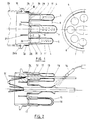
- a re-openable splice closure comprises a one-piece tubular sleeve 26 which is closed at one end (not shown) and has its other, open end fitted to the base assembly 1,2 so as to enclose cable joints or splices.
- the base assembly 1,2 has a tubular section 1a with a portion which fits within the open end of the sleeve 26 and an annular flange 1b which abuts the end of the sleeve.
- a radially outwardly projecting annular flange 26a at the end or sleeve 26 abuts the flange 1b of the base with the interposition of an O-ring seal 10.
- the sleeve 26 is held in place on the base by a split clamping ring (not shown) having a groove on its inner periphery receiving the flanges 1b, 26a.
- the base assembly comprises a rigid member 1 formed of heat resistant thermoset polymer and formed by injection moulding, typically by a dough compression moulding process.
- the outer end of the rigid member 1 is closed but provided with a multiplicity of tubular projections 1c.
- the inner end of each of these is closed by a membrane 28 having a reduced-thickness periphery as shown at e.g. 29, 30.
- the splice closure base assembly further comprises a moulded member 2 having a skirt 2a which fits closely around the outside of the tubular section 1a of the member 1, and a plurality of tubular projections 3, 4 which fit closely around the respective tubular projections 1c of the member 1.
- the tubular projections 3, 4 are approximately twice as long as the projections 1c of the member 1: the projections 3, 4 are of relatively large wall thickness for half their lengths, covering the projections 1c, and of reduced wall thickness for the remainder of their lengths 4, and are closed at their outer or free ends e.g. 5, 7.
- the end portions 4 are in an expanded condition so as to be heat-shrinkable, and are capable of recovering to the shape indicated at 11.
- the heat shrink moulded member 2 is sealed to the member 1 using a hot melt adhesive having a melt temperature above that likely to be experienced through conduction or convection when heat is applied to the recoverable portions 4: an adhesive melt temperature above 60° is unlikely to be required.
- the member 2 is further held to the member 1 by a band 6 (e.g. of stainless steel or high performance polymer) tightened around the skirt 2a of member 2 and the underlying tubular section of member 1.
- the base member 1 is formed with integral partition walls 27 to define individual compartments within its tubular section 1a registering with the respective tubular projections 1c.
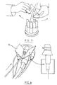
- a kit for forming the cable splice closure comprises the base assembly 1,2, the sleeve 26 and one or more tubular heat shields as shown in Figure 3.
- this tubular heat shield comprises a ceramic fibre material capable of providing insulation against temperatures in excess of 1000°C to ensure adequate protection for the cable entry port to which it is applied.
- the heatshield is cylindrical or otherwise shaped in cross-section (e.g. oval) to match the cross section of the cable entry ports.
- the heat shield has half of its length 18 of relatively large inner diameter to fit over the larger diameter half of the cable entry port, and half of its length 19 of reduced diameter to fit over the reduced diameter end of the cable entry port.
- the heatshield is closed at its outer end.
- a slit 22 is provided along the side of the heatshield and to the centre of its closed end to enable it to be applied to a cable entry which already has a cable installed therein, as shown in Figure 2 at 13.
- the heatshield is formed with a convoluted wall as shown, to allow for expanding the heatshield to fit over the cable entry port and thus grip the latter.
- the rounded, closed end 15 of the heatshield is formed with an inwards deformation 20 which serves for gripping and sealing any cable around which the heatshield is applied.
- the splice closure is formed of the sleeve 26 and the splice closure base 1, 2 fitted into the open end of the sleeve.
- the base has a greater number of cable entry ports than is required for the initial cable installation, thus permitting additional or replacement cables to be installed using the free ports.
- Figure 2 shows a situation where a cable 13 is already installed through one entry port and this has been recovered about the cable. Now another cable has been installed through another port and this port is being recovered about the new cable using a gas flame heating torch 14: before this torch is applied, however, heatshields as shown in Figure 3 are fitted to the neighbouring ports to protect them from the applied heat. Heatshields are fitted both to entry ports through which cables have already been installed, and to unused ports. Individual conductors of the cables are interconnected by splices, one of which is shown at 31.
- the port and associated compartment within the base member 1 are filled with resin as shown at 12 in Figure 2, in order to provide a seal additional to that provided by the recovered port. It will be noted that by providing such a compartment, the resin encapsulates a length of the individual conductors themselves as they emerge from the end of the cable sheath and furthermore seal the end of this sheath. Any ports which are not likely to be needed can be blanked off by filling the associated compartment with resin, without removing the corresponding membrane 28.
- the joint closure kit may include the alternative forms of heat shield shown in Figures 4 to 6.
- the joint closure base has a central entry port 40 which projects axially outwards further than the surrounding entry ports 42, and the central entry port 40 is of generally oval cross-section for receiving two cables side by side.
- a heat shield 44 comprises a flat piece of ceramic material with an oval aperture 46 therein, and this is placed over the central entry port so that the heat-shrinkable end portion of the latter projects through the aperture 46. Heat may then be applied to recover this portion of the entry port about the cables installed through it, the heatshield 44 insulating the other entry ports from this heat. The heat shield 44 is then removed by tearing it through from one edge to the aperture 46 as shown in Figure 5.
- Heat shield 50 is of V shape and is placed around the cable entry port which is to be recovered.
- the heat shield 50 comprises two pieces of the ceramic heat insulating material hinged together, by means for example of an aluminium foil backing.
Landscapes
- Physics & Mathematics (AREA)
- General Physics & Mathematics (AREA)
- Optics & Photonics (AREA)
- Cable Accessories (AREA)
- Separation By Low-Temperature Treatments (AREA)
- Optical Communication System (AREA)
- Processing Of Terminals (AREA)
Claims (8)
- Grundteilanordnung für einen wieder zu öffnenden Kabelspleißverschluß, welche Grundteilanordnung ein einstückiges Grundteilglied (1) starrer Konstruktion mit einer Vielzahl von röhrenförmigen Vorsprüngen (1c), die sich davon erstrecken, wobei die röhrenförmigen Vorsprünge (1c) Kabeleintrittsdurchlässe bilden und das einstückige starre Grundteilglied zerbrechbare Membranen (28) aufweist, die die axial inneren Enden der röhrenförmigen Vorsprünge (1c) abschließen, und eine Vielzahl von röhrenförmigen Elementen (3,4) aufweist, die um die entsprechenden röhrenförmigen Vorsprünge (1c) des einstückigen starren Grundteilgliedes (1) engpassend angeordnet sind, wobei die röhrenförmigen Elemente (3,4) Teile (4) haben, die über die freien axial äußeren Enden der entsprechenden röhrenförmigen Vorsprünge (1c) des einstückigen starren Grundteilgliedes (1) herausragen, wobei die herausragenden Teile (4) der röhrenförmigen Elemente (3,4) wärmeschrumpfbar sind, dadurch gekennzeichnet, daß die Vielzahl von röhrenförmigen Vorsprüngen (1c) von dem einstückigen Grundteilglied (1) in einer Richtung vorstehen, die in bezug auf den Kabelspleißverschluß, wenn der Spleißverschluß gebildet ist, nach außen gerichtet ist, und daß die röhrenförmigen Elemente (3,4) Teile eines separaten Gliedes (2) bilden.
- Kabelspleißverschluß-Grundteilanordnung nach Anspruch 1, dadurch gekennzeichnet, daß der wärmeschrumpfbare Teil (4) jedes röhrenförmigen Elementes (3,4) an seinem freien axial äußeren Ende (5) verschlossen ist.
- Kabelspleißverschluß-Grundteilanordnung nach Anspruch 1 oder 2, dadurch gekennzeichnet, daß das einstückige starre Grundteilglied (1) mit einer Vielzahl von inneren Abteilen ausgebildet ist, die mit entsprechenden röhrenförmigen Vorsprüngen (1c) ausgerichtet sind.
- Ausstattung zum Bilden eines wieder zu öffnenden Kabelspleißverschlusses, wobei die Ausstattung eine Grundteilanordnung (1,2), die ein einstückiges Grundteilglied (1) von starrer Konstruktion mit einer Vielzahl von röhrenförmigen Vorsprüngen (1c) aufweist, die sich davon erstrecken, um Kabeleintrittsdurchlässe zu bilden, wobei das einstückige starre Grundteilglied (1) zerbrechbare Membranen (28) aufweist, die die axial inneren Enden der röhrenförmigen Vorsprünge (1c) abschließen, und eine Vielzahl von röhrenförmigen Elementen (3,4) aufweist, die um entsprechende röhrenförmige Vorsprünge (1c) des einstückigen starren Grundteilgliedes (1) engpassend angeordnet sind, wobei die röhrenförmigen Elemente (3,4) Teile (4) haben, die über die freien axial äußeren Enden der entsprechenden röhrenförmigen Vorsprünge (1c) des einstückigen Grundteilgliedes (1) vorstehen, wobei die vorstehenden Teile (4) der röhrenförmigen Elemente (3,4) wärmeschrumpfbar sind, dadurch gekennzeichnet, daß die Vielzahl von röhrenförmigen Vorsprüngen (1c) von dem einstückigen Grundteilglied (1) in einer Richtung vorstehen, die in bezug auf den Kabelspleißverschluß, wenn der Spleißverschluß gebildet ist, nach außen gerichtet ist, daß die röhrenförmigen Elemente (3,4) Teile eines separaten Gliedes (2) bilden, und daß wenigstens eine Wärmeabschirmung vorgesehen ist, um wenigstens ein röhrenförmiges Element (3,4) thermisch zu isolieren, wenn Wärme angewendet wird, um wenigstens ein anderes röhrenförmiges Element (3,4) einer Wärmeschrumpfung auszusetzen.
- Ausstattung nach Anspruch 4, dadurch gekennzeichnet, daß die wenigstens eine Wärmeabschirmung von röhrenförmiger Form ist, um über ein röhrenförmiges Element (3,4) aufgesetzt zu werden, unabhängig davon, ob das röhrenförmige Element (3,4) expandierte Form oder wärmegeschrumpfte Form hat.
- Ausstattung nach Anspruch 4, dadurch gekennzeichnet, daß eine Wärmeabschirmung (50) allgemein V-förmig oder C-förmig ist, um um ein röhrenförmiges Element (3,4) angelegt zu werden, das einer Wärmeschrumpfung unterzogen werden soll, und um benachbarte röhrenförmige Elemente (3,4) von Wärme abzuschirmen, die auf das röhrenförmige Element angewendet wird.
- Ausstattung nach Anspruch 4, dadurch gekennzeichnet, daß die Wärmeabschirmung ein mit einer Öffnung versehenes Stück von thermisch isolierendem Material zum Aufsetzen über ein röhrenförmiges Element (40) aufweist, welches röhrenförmige Element axial über die freien Enden der anderen röhrenförmigen Elemente (3,4) herausragt, so daß Wärme auf das eine röhrenförmige Element (40) angewendet werden kann, um eine Wärmeschrumpfung desselben zu bewirken, während die anderen röhrenförmigen Elemente von der angewandten Wärme isoliert werden.
- Verfahren zum Bilden eines wieder zu öffnenden Kabelspleißverschlusses, das die Schritte aufweist: eine Verschlußgrundteilanordnung (1,2) zur Verfügung zu stellen, die ein einstückiges Grundteilglied von starrer Konstruktion mit einer Vielzahl von röhrenförmigen Vorsprüngen (1c) aufweist, die sich davon erstrecken, um Kabeleintrittsdurchlässe zu bilden, wobei das einstückige starre Grundteilglied (1) zerbrechbare Membranen (28) einschließt, die die axial inneren Enden der röhrenförmigen Vorsprünge (1c) abschließen, wobei die Grundteilanordnung weiter eine Vielzahl von röhrenförmigen Elementen (3,4) aufweist, die engpassend um die entsprechenden röhrenförmigen Vorsprünge (1c) des einstückigen starren Grundteilgliedes (1) angeordnet sind, wobei die röhrenförmigen Vorsprünge (3,4) Teile (4) haben, die über die freien axial äußeren Enden der entsprechenden röhrenförmigen Vorsprünge (1c) des einstückigen Grundteilgliedes (1) herausragen, wobei die herausragenden Teile (4) der röhrenförmigen Elemente (3,4) wärmeschrumpfbar sind; die zerbrechbare Membran (28) wenigstens eines röhrenförmigen Vorsprunges (1c) des einstückigen Grundteilgliedes (1) der Verschlußgrundteilanordnung (1,2) zu zerbrechen; ein Kabel durch den einen röhrenförmigen Vorsprung (1c) hindurchzuführen; und Wärme auf ein wärmeschrumpfbares röhrenförmiges Element (4) anzuwenden, um einen Verschluß oder eine Dichtung zwischen dem Kabel und dem einen röhrenförmigen Vorsprung (1c) zu bilden, dadurch gekennzeichnet, daß die Vielzahl von röhrenförmigen Vorsprüngen (1c) von dem einstückigen Grundteilelement (1) in einer Richtung vorstehen, die in bezug auf den Kabelspleißverschluß, der gebildet wird, nach außen gerichtet ist, daß die röhrenförmigen Elemente (3,4) Teile eines separaten Gliedes (2) bilden; und daß, während Wärme auf den vorstehenden Teil (4) des röhrenförmigen Elementes (3,4) angewendet wird, durch das das Kabel hindurchgeführt ist, um diesen vorstehenden Teil (4) einer Wärmeschrumpfung zu unterziehen, wenigstens eine Wärmeabschirmung verwendet wird, um die anderen röhrenförmigen Elemente (3,4) von der angewendeten Wärme zu isolieren.
Applications Claiming Priority (5)
| Application Number | Priority Date | Filing Date | Title |
|---|---|---|---|
| GB898900163A GB8900163D0 (en) | 1989-01-05 | 1989-01-05 | Splice closures |
| GB8900163 | 1989-01-05 | ||
| GB8920706A GB2227893B (en) | 1989-01-05 | 1989-09-13 | Splice closures |
| GB8920706 | 1989-09-13 | ||
| PCT/GB1990/000003 WO1990007812A1 (en) | 1989-01-05 | 1990-01-02 | Splice closures |
Publications (2)
| Publication Number | Publication Date |
|---|---|
| EP0452383A1 EP0452383A1 (de) | 1991-10-23 |
| EP0452383B1 true EP0452383B1 (de) | 1994-12-07 |
Family
ID=26294801
Family Applications (1)
| Application Number | Title | Priority Date | Filing Date |
|---|---|---|---|
| EP90901632A Expired - Lifetime EP0452383B1 (de) | 1989-01-05 | 1990-01-02 | Spleissverschlüsse |
Country Status (6)
| Country | Link |
|---|---|
| US (1) | US5208428A (de) |
| EP (1) | EP0452383B1 (de) |
| AU (1) | AU633864B2 (de) |
| CA (1) | CA2044585C (de) |
| DE (1) | DE69014859T2 (de) |
| WO (1) | WO1990007812A1 (de) |
Cited By (1)
| Publication number | Priority date | Publication date | Assignee | Title |
|---|---|---|---|---|
| US5610369A (en) * | 1992-11-03 | 1997-03-11 | Bowthorpe Plc | Cable splice closure |
Families Citing this family (11)
| Publication number | Priority date | Publication date | Assignee | Title |
|---|---|---|---|---|
| CA2044585C (en) * | 1989-01-05 | 1995-07-25 | Raymond Charles Foss | Splice closures |
| DK0584616T3 (da) * | 1992-08-19 | 1996-08-26 | Rxs Schrumpftech Garnituren | Indretning til multikabelindføringer ved kabelmuffer |
| US5442140A (en) * | 1993-10-05 | 1995-08-15 | Homac Mfg. Company | Conduit and cable sealer |
| GB9704037D0 (en) * | 1997-02-27 | 1997-04-16 | Fibresec Holding Ltd | Cable sealing |
| GB9828168D0 (en) * | 1998-12-22 | 1999-02-17 | Bicc Plc | Cable system for use in hazardous environments |
| US6292614B1 (en) | 1999-08-24 | 2001-09-18 | Siecor Operations, Llc | Movable bracket for holding internal components of an optical fiber interconnection closure during servicing and associated method |
| IES20030313A2 (en) * | 2003-04-25 | 2004-11-03 | Paltexa Ltd | An improved cable joint closure system |
| US7339115B2 (en) * | 2005-07-15 | 2008-03-04 | Rockbestos Surprenant Cable Corp | Fire resistant electrical cable splice |
| US8977089B2 (en) * | 2009-05-06 | 2015-03-10 | Yu-Fen Chi | Cable connection housing providing multiple methods for waterproofing main cables |
| CN103109221B (zh) | 2010-09-21 | 2015-11-25 | 胡贝尔和茹纳股份公司 | 环境密封的电缆分支组件 |
| US9601910B2 (en) * | 2013-11-18 | 2017-03-21 | Carlos M. Santos | Riser glove, enclosure glove and strain releasing connectors |
Family Cites Families (16)
| Publication number | Priority date | Publication date | Assignee | Title |
|---|---|---|---|---|
| US3395382A (en) * | 1966-06-06 | 1968-07-30 | Sigma Ind Inc | Re-enterable electrical assembly |
| US3624594A (en) * | 1969-02-14 | 1971-11-30 | Amp Inc | Electrical connector assembly |
| US3614295A (en) * | 1969-10-06 | 1971-10-19 | George W Gillemot | Cable splice kit and method of use in making branchout service connections |
| US3725581A (en) * | 1971-08-02 | 1973-04-03 | G Gillemot | Re-enterable cable splice assembly and method including provision for adding branchout service cables as needed |
| GB1594693A (en) * | 1976-10-29 | 1981-08-05 | Raychem Sa Nv | Heatrecoverable article |
| CH627880A5 (de) * | 1978-03-23 | 1982-01-29 | Bbc Brown Boveri & Cie | Aderaufteilvorrichtung an einem mehrleiterleistungskabel und verfahren zur herstellung einer derartigen vorrichtung. |
| GB2046030A (en) * | 1979-03-30 | 1980-11-05 | A C Egerton Eng Bromley Ltd | Sleeve assembly for sealing a joint between two cable ends |
| IL62765A (en) * | 1980-05-03 | 1985-07-31 | Raychem Ltd | Manufacture of dimensionally recoverable articles |
| CA1232347A (en) * | 1982-05-19 | 1988-02-02 | Joris R.I. Franckx | Cable joint enclosure |
| GB8310014D0 (en) * | 1983-04-13 | 1983-05-18 | Raychem Sa Nv | Feedthrough device |
| GB8413361D0 (en) * | 1984-05-24 | 1984-06-27 | Raychem Sa Nv | Sealed electrical connector |
| DE3607355C1 (de) * | 1986-03-06 | 1987-09-17 | Rose Walter Gmbh & Co Kg | Vorrichtung zum Abdichten von Kabeln |
| GB8608109D0 (en) * | 1986-04-03 | 1986-05-08 | Bowthorpe Hellermann Ltd | Joint closure |
| US4769513A (en) * | 1986-06-10 | 1988-09-06 | Raychem Corporation | Splice closure system |
| US4924034A (en) * | 1987-10-06 | 1990-05-08 | Raychem Corporation | Re-enterable enclosure around splice |
| CA2044585C (en) * | 1989-01-05 | 1995-07-25 | Raymond Charles Foss | Splice closures |
-
1990
- 1990-01-02 CA CA002044585A patent/CA2044585C/en not_active Expired - Fee Related
- 1990-01-02 US US07/721,429 patent/US5208428A/en not_active Expired - Fee Related
- 1990-01-02 AU AU48139/90A patent/AU633864B2/en not_active Ceased
- 1990-01-02 EP EP90901632A patent/EP0452383B1/de not_active Expired - Lifetime
- 1990-01-02 WO PCT/GB1990/000003 patent/WO1990007812A1/en active IP Right Grant
- 1990-01-02 DE DE69014859T patent/DE69014859T2/de not_active Expired - Fee Related
Cited By (1)
| Publication number | Priority date | Publication date | Assignee | Title |
|---|---|---|---|---|
| US5610369A (en) * | 1992-11-03 | 1997-03-11 | Bowthorpe Plc | Cable splice closure |
Also Published As
| Publication number | Publication date |
|---|---|
| DE69014859D1 (de) | 1995-01-19 |
| AU4813990A (en) | 1990-08-01 |
| AU633864B2 (en) | 1993-02-11 |
| EP0452383A1 (de) | 1991-10-23 |
| CA2044585C (en) | 1995-07-25 |
| WO1990007812A1 (en) | 1990-07-12 |
| US5208428A (en) | 1993-05-04 |
| DE69014859T2 (de) | 1995-04-13 |
Similar Documents
| Publication | Publication Date | Title |
|---|---|---|
| US4142592A (en) | Repairable assembly for protecting a cable junction and method of assembling same | |
| US4421945A (en) | Junction assembly | |
| EP0452383B1 (de) | Spleissverschlüsse | |
| US4289553A (en) | Heat-shrinkable article | |
| JPH01295615A (ja) | テーパ状突起付きライナー | |
| US5426715A (en) | Oval port seal and method used for an optical fiber cable closure | |
| AU757414B2 (en) | Cable closure | |
| EP0320189A2 (de) | Kabelverschlussvorrichtung | |
| EP0201533B1 (de) | Verfahren und vorrichtung zum schliessen unter druck einer übertragungskabelverbindung | |
| US5235134A (en) | Sealed reenterable splice enclosure | |
| US4924034A (en) | Re-enterable enclosure around splice | |
| US6177634B1 (en) | Splice Closure | |
| AU7502294A (en) | Sealing member | |
| US3209069A (en) | Joint enclosure for joined electric cables | |
| EP0236141B1 (de) | Methode und Vorrichtung zum Abdichten von Kabeln | |
| AU657812B2 (en) | A cable sleeve composed of a longitudinally-divided housing | |
| EP0628221B1 (de) | Kabelabdichtung | |
| JPS62185511A (ja) | 分割エンドシ−ルおよびクロ−ジヤ− | |
| JP5016714B2 (ja) | ブスバー端部接続部を密封するための安全プラグ | |
| EP0267028A2 (de) | Zusammenbau eines Verschlusses | |
| GB2227893A (en) | Electrical or optical fibre lead through | |
| GB1603626A (en) | Junction assembly | |
| EP0764355B1 (de) | Spleissgehäuse | |
| GB2210736A (en) | Re-enterable enclosure for cable splice | |
| EP0082010B1 (de) | Einlage für einen Verschlusszusammenbau |
Legal Events
| Date | Code | Title | Description |
|---|---|---|---|
| PUAI | Public reference made under article 153(3) epc to a published international application that has entered the european phase |
Free format text: ORIGINAL CODE: 0009012 |
|
| 17P | Request for examination filed |
Effective date: 19910703 |
|
| AK | Designated contracting states |
Kind code of ref document: A1 Designated state(s): BE DE FR |
|
| 17Q | First examination report despatched |
Effective date: 19930429 |
|
| GRAA | (expected) grant |
Free format text: ORIGINAL CODE: 0009210 |
|
| AK | Designated contracting states |
Kind code of ref document: B1 Designated state(s): BE DE FR |
|
| REF | Corresponds to: |
Ref document number: 69014859 Country of ref document: DE Date of ref document: 19950119 |
|
| ET | Fr: translation filed | ||
| PLBE | No opposition filed within time limit |
Free format text: ORIGINAL CODE: 0009261 |
|
| STAA | Information on the status of an ep patent application or granted ep patent |
Free format text: STATUS: NO OPPOSITION FILED WITHIN TIME LIMIT |
|
| 26N | No opposition filed | ||
| PGFP | Annual fee paid to national office [announced via postgrant information from national office to epo] |
Ref country code: FR Payment date: 20020110 Year of fee payment: 13 |
|
| PGFP | Annual fee paid to national office [announced via postgrant information from national office to epo] |
Ref country code: DE Payment date: 20020212 Year of fee payment: 13 |
|
| PGFP | Annual fee paid to national office [announced via postgrant information from national office to epo] |
Ref country code: BE Payment date: 20020320 Year of fee payment: 13 |
|
| PG25 | Lapsed in a contracting state [announced via postgrant information from national office to epo] |
Ref country code: BE Free format text: LAPSE BECAUSE OF NON-PAYMENT OF DUE FEES Effective date: 20030131 |
|
| PG25 | Lapsed in a contracting state [announced via postgrant information from national office to epo] |
Ref country code: DE Free format text: LAPSE BECAUSE OF NON-PAYMENT OF DUE FEES Effective date: 20030801 |
|
| PG25 | Lapsed in a contracting state [announced via postgrant information from national office to epo] |
Ref country code: FR Free format text: LAPSE BECAUSE OF NON-PAYMENT OF DUE FEES Effective date: 20030930 |
|
| REG | Reference to a national code |
Ref country code: FR Ref legal event code: ST |