EP0451925A1 - Système d'ancre - Google Patents
Système d'ancre Download PDFInfo
- Publication number
- EP0451925A1 EP0451925A1 EP91200872A EP91200872A EP0451925A1 EP 0451925 A1 EP0451925 A1 EP 0451925A1 EP 91200872 A EP91200872 A EP 91200872A EP 91200872 A EP91200872 A EP 91200872A EP 0451925 A1 EP0451925 A1 EP 0451925A1
- Authority
- EP
- European Patent Office
- Prior art keywords
- anchor
- sheeting
- leg
- insertion sheet
- bottom edge
- Prior art date
- Legal status (The legal status is an assumption and is not a legal conclusion. Google has not performed a legal analysis and makes no representation as to the accuracy of the status listed.)
- Granted
Links
- 230000037431 insertion Effects 0.000 claims abstract description 22
- 238000003780 insertion Methods 0.000 claims abstract description 22
- 229910000831 Steel Inorganic materials 0.000 claims abstract description 9
- 239000010959 steel Substances 0.000 claims abstract description 9
- 230000004308 accommodation Effects 0.000 claims abstract description 3
- 230000015572 biosynthetic process Effects 0.000 claims abstract description 3
- 229910000278 bentonite Inorganic materials 0.000 description 3
- 239000000440 bentonite Substances 0.000 description 3
- SVPXDRXYRYOSEX-UHFFFAOYSA-N bentoquatam Chemical compound O.O=[Si]=O.O=[Al]O[Al]=O SVPXDRXYRYOSEX-UHFFFAOYSA-N 0.000 description 3
- 229920001903 high density polyethylene Polymers 0.000 description 2
- 239000004700 high-density polyethylene Substances 0.000 description 2
- 239000000203 mixture Substances 0.000 description 2
- 239000004927 clay Substances 0.000 description 1
- 239000003673 groundwater Substances 0.000 description 1
- 238000002955 isolation Methods 0.000 description 1
- 239000004033 plastic Substances 0.000 description 1
- 229920003023 plastic Polymers 0.000 description 1
- 125000006850 spacer group Chemical group 0.000 description 1
- XLYOFNOQVPJJNP-UHFFFAOYSA-N water Substances O XLYOFNOQVPJJNP-UHFFFAOYSA-N 0.000 description 1
Images
Classifications
-
- E—FIXED CONSTRUCTIONS
- E02—HYDRAULIC ENGINEERING; FOUNDATIONS; SOIL SHIFTING
- E02D—FOUNDATIONS; EXCAVATIONS; EMBANKMENTS; UNDERGROUND OR UNDERWATER STRUCTURES
- E02D19/00—Keeping dry foundation sites or other areas in the ground
- E02D19/06—Restraining of underground water
- E02D19/12—Restraining of underground water by damming or interrupting the passage of underground water
- E02D19/18—Restraining of underground water by damming or interrupting the passage of underground water by making use of sealing aprons, e.g. diaphragms made from bituminous or clay material
Definitions
- the invention relates to an anchor intended for fitting at the bottom edge of a sheeting panel which has to be pressed by means of a steel insertion sheet into a ground trench as part of a wall comprising sheeting panels interconnected by section connections, which anchor is U-shaped.
- an anchor of the type mentioned in the preamble In order to anchor a panel after it has been pushed into the ground trench, use is made of an anchor of the type mentioned in the preamble.
- the known anchor is fixed to the bottom edge of a sheeting panel by means of a separate strip and screws. Rib-shaped spacers which prevent the insertion sheet from sticking to the sheeting panel are fitted between the insertion sheet and the sheeting panel. Fixing of the anchor to a sheeting panel is time-consuming.
- the object of the invention is to produce the connection between anchor and sheeting panel considerably more quickly without there being any risk of wedging occurring between insertion sheet and anchor as a result of which the sheeting panel would be pulled up with the insertion sheet during the raising of said sheet after the insertion of said sheeting panel and the locks between the panels could consequently spring apart.
- the anchor is to this end characterized in that the top piece of one of the legs of the U is bent in the direction of the other leg for the formation of a separate accommodation chamber for a thickened part present at the bottom edge of the sheeting panel, while a space exists between the free edge of the inward bent leg part and the above-mentioned other leg for the purpose of allowing through the bottom edge of the steel insertion sheet, and in that a number of recesses are provided in the anchor section for the purpose of reducing the longitudinal rigidity of the anchor.
- the virtually vertical-running recesses in the vertical leg of the U of the anchor section which can lie against the insertion sheet during the insertion of the sheeting panel, reduce the local rigidity of the anchor section.
- the correct wedging between anchor section and insertion sheet can be achieved by providing the correct number of such recesses over the length of the anchor section and/or adapting the length and/or the breadth of said recesses, depending on the shape of anchor section and/or bottom part of the insertion sheet, as a result of which the insertion sheet can be removed from the anchor without too much force after the sheeting panel has been pressed into the lowest position and, in addition, the sheeting panel with its locks is not placed under unnecessary stress.
- the recesses can continue into a part of the bottom of the U.
- the breadth of the recesses preferably lies between 0.5 and 300 mm.
- projecting centring wings can be fixed on the anchor on both sides.
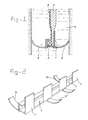
- Figure 1 shows a cross-section through the bottom part of an anchor according to the invention with insertion sheet and sheeting panel.
- Figure 2 shows a perspective view of the anchor.
- the steel anchor 1 shown in the figures is in the shape of a U of which one of the flanges is bent inwards at its top part for the purpose of forming a channel into which the thickened bottom edge 2 of a sheeting panel 3 is pushed.
- This sheeting panel is made of plastic, for example HDPE, and is connected in a manner which is known per se by edge locking sections to a sheeting panel already placed in the trenches.
- a steel insertion sheet for pressing the sheeting panel with anchor into a ground trench 4 filled with bentonite mixture is indicated by 5 and projects with its bottom edge into the anchor.
- centring wings 6 are fixed to the anchor 1, projecting on either side. These wings end in an upward-sloping part, so that during the downward movement of the anchor they cannot become jammed in the trench wall when they come into contact with said wall.
- the wings are welded to the bottom of the anchor section, but they can also be connected to the anchor section at other places.
- the wings 6 at both sides of the anchor section can also be fixed as a continuous unit to the bottom side of the anchor section.
- Vertical-running recesses 7 are provided in order to be able to adjust the local wedging between anchor section 1 and the insertion sheet 5. These recesses are preferably of a minimum breadth of 0.5 mm and a maximum breadth of 300 mm. They can continue into the bottom of the U.
Landscapes
- Engineering & Computer Science (AREA)
- Life Sciences & Earth Sciences (AREA)
- Environmental & Geological Engineering (AREA)
- Hydrology & Water Resources (AREA)
- General Life Sciences & Earth Sciences (AREA)
- Mining & Mineral Resources (AREA)
- Paleontology (AREA)
- Civil Engineering (AREA)
- General Engineering & Computer Science (AREA)
- Structural Engineering (AREA)
- Piles And Underground Anchors (AREA)
Applications Claiming Priority (2)
| Application Number | Priority Date | Filing Date | Title |
|---|---|---|---|
| NL9000875A NL9000875A (nl) | 1990-04-12 | 1990-04-12 | Anker. |
| NL9000875 | 1990-04-12 |
Publications (2)
| Publication Number | Publication Date |
|---|---|
| EP0451925A1 true EP0451925A1 (fr) | 1991-10-16 |
| EP0451925B1 EP0451925B1 (fr) | 1993-07-14 |
Family
ID=19856923
Family Applications (1)
| Application Number | Title | Priority Date | Filing Date |
|---|---|---|---|
| EP19910200872 Expired - Lifetime EP0451925B1 (fr) | 1990-04-12 | 1991-04-12 | Système d'ancre |
Country Status (3)
| Country | Link |
|---|---|
| EP (1) | EP0451925B1 (fr) |
| DE (1) | DE69100167T2 (fr) |
| NL (1) | NL9000875A (fr) |
Citations (3)
| Publication number | Priority date | Publication date | Assignee | Title |
|---|---|---|---|---|
| US3479933A (en) * | 1968-01-11 | 1969-11-25 | Brown Co D S | Elongated,hollow,elastomer sealing strip with elongated,laterally deformable spring |
| EP0074686A1 (fr) * | 1981-09-15 | 1983-03-23 | Volker Stevin Beton- En Waterbouw B.V. | Méthode pour la réalisation dans le sol d'un écran, étanche à l'eau, et écran et dispositif pour l'application de la méthode |
| DE3540270A1 (de) * | 1985-11-13 | 1987-05-14 | Wayss & Freytag Ag | Verfahren zur herstellung einer dichtwand und vorrichtung zur durchfuehrung des verfahrens |
-
1990
- 1990-04-12 NL NL9000875A patent/NL9000875A/nl not_active Application Discontinuation
-
1991
- 1991-04-12 DE DE1991600167 patent/DE69100167T2/de not_active Expired - Fee Related
- 1991-04-12 EP EP19910200872 patent/EP0451925B1/fr not_active Expired - Lifetime
Patent Citations (3)
| Publication number | Priority date | Publication date | Assignee | Title |
|---|---|---|---|---|
| US3479933A (en) * | 1968-01-11 | 1969-11-25 | Brown Co D S | Elongated,hollow,elastomer sealing strip with elongated,laterally deformable spring |
| EP0074686A1 (fr) * | 1981-09-15 | 1983-03-23 | Volker Stevin Beton- En Waterbouw B.V. | Méthode pour la réalisation dans le sol d'un écran, étanche à l'eau, et écran et dispositif pour l'application de la méthode |
| DE3540270A1 (de) * | 1985-11-13 | 1987-05-14 | Wayss & Freytag Ag | Verfahren zur herstellung einer dichtwand und vorrichtung zur durchfuehrung des verfahrens |
Also Published As
| Publication number | Publication date |
|---|---|
| DE69100167D1 (de) | 1993-08-19 |
| EP0451925B1 (fr) | 1993-07-14 |
| DE69100167T2 (de) | 1993-10-28 |
| NL9000875A (nl) | 1991-11-01 |
Similar Documents
| Publication | Publication Date | Title |
|---|---|---|
| US6672016B2 (en) | Wall and sub-floor water drain barrier panel for basement water-control systems | |
| US5340234A (en) | Trench drain system and installation method | |
| US5399050A (en) | Plastic concrete form for footers | |
| US4699544A (en) | Protective frame device for drainage channel | |
| CA2495749C (fr) | Systeme de renfort pour unites de mur de soutenement empilables | |
| EP0180439B1 (fr) | Système de drainage pour sous-sols | |
| US3848378A (en) | Stairs for swimming pools | |
| US5735637A (en) | Method and apparatus for supporting and anchoring drainage channel sections | |
| US5035095A (en) | Basement wall structure to prevent water leakage | |
| US5473845A (en) | Modular fastening system | |
| US4274763A (en) | Excavating sheeting unit | |
| US5794393A (en) | Concrete foundation wall form apparatus and method | |
| US3986310A (en) | Modular swimming pool structure and method for its erection | |
| US3064273A (en) | Swimming pool | |
| US4930272A (en) | Drain system | |
| JPS6314124B2 (fr) | ||
| JP3977848B2 (ja) | 浮体利用の簡易防水板 | |
| GB2086456A (en) | Flood barrier | |
| US975665A (en) | Shoring. | |
| EP0451925A1 (fr) | Système d'ancre | |
| US5984576A (en) | Mobile demountable liquid protective wall from horizontally s-shape indented profile elements, which can be stacked on top of each other | |
| JP3709550B2 (ja) | コンクリ−ト擁壁 | |
| EP0026782B1 (fr) | Paroi de retenue du sol et de l'eau, formee de plaques prefabriquees | |
| JPS6033160Y2 (ja) | 土木建築用ブロツク | |
| JPH07127051A (ja) | 連続地中壁施工用鉄筋篭の構造及びその建込み方法 |
Legal Events
| Date | Code | Title | Description |
|---|---|---|---|
| PUAI | Public reference made under article 153(3) epc to a published international application that has entered the european phase |
Free format text: ORIGINAL CODE: 0009012 |
|
| AK | Designated contracting states |
Kind code of ref document: A1 Designated state(s): BE DE GB LU NL |
|
| 17P | Request for examination filed |
Effective date: 19911112 |
|
| 17Q | First examination report despatched |
Effective date: 19920427 |
|
| GRAA | (expected) grant |
Free format text: ORIGINAL CODE: 0009210 |
|
| AK | Designated contracting states |
Kind code of ref document: B1 Designated state(s): BE DE GB LU NL |
|
| REF | Corresponds to: |
Ref document number: 69100167 Country of ref document: DE Date of ref document: 19930819 |
|
| PLBE | No opposition filed within time limit |
Free format text: ORIGINAL CODE: 0009261 |
|
| STAA | Information on the status of an ep patent application or granted ep patent |
Free format text: STATUS: NO OPPOSITION FILED WITHIN TIME LIMIT |
|
| EPTA | Lu: last paid annual fee | ||
| 26N | No opposition filed | ||
| REG | Reference to a national code |
Ref country code: GB Ref legal event code: IF02 |
|
| PGFP | Annual fee paid to national office [announced via postgrant information from national office to epo] |
Ref country code: GB Payment date: 20050407 Year of fee payment: 15 |
|
| PGFP | Annual fee paid to national office [announced via postgrant information from national office to epo] |
Ref country code: BE Payment date: 20050421 Year of fee payment: 15 |
|
| PGFP | Annual fee paid to national office [announced via postgrant information from national office to epo] |
Ref country code: LU Payment date: 20050425 Year of fee payment: 15 |
|
| PGFP | Annual fee paid to national office [announced via postgrant information from national office to epo] |
Ref country code: DE Payment date: 20050427 Year of fee payment: 15 |
|
| PGFP | Annual fee paid to national office [announced via postgrant information from national office to epo] |
Ref country code: NL Payment date: 20050429 Year of fee payment: 15 |
|
| PG25 | Lapsed in a contracting state [announced via postgrant information from national office to epo] |
Ref country code: GB Free format text: LAPSE BECAUSE OF NON-PAYMENT OF DUE FEES Effective date: 20060412 |
|
| PG25 | Lapsed in a contracting state [announced via postgrant information from national office to epo] |
Ref country code: LU Free format text: LAPSE BECAUSE OF NON-PAYMENT OF DUE FEES Effective date: 20060430 Ref country code: BE Free format text: LAPSE BECAUSE OF NON-PAYMENT OF DUE FEES Effective date: 20060430 |
|
| PG25 | Lapsed in a contracting state [announced via postgrant information from national office to epo] |
Ref country code: NL Free format text: LAPSE BECAUSE OF NON-PAYMENT OF DUE FEES Effective date: 20061101 Ref country code: DE Free format text: LAPSE BECAUSE OF NON-PAYMENT OF DUE FEES Effective date: 20061101 |
|
| GBPC | Gb: european patent ceased through non-payment of renewal fee |
Effective date: 20060412 |
|
| NLV4 | Nl: lapsed or anulled due to non-payment of the annual fee |
Effective date: 20061101 |
|
| BERE | Be: lapsed |
Owner name: HOLLANDSCHE *BETON GROEP N.V. Effective date: 20060430 |