EP0451689A2 - Indicateur du niveau d'un réservoir d'eau pour un appareil ménager - Google Patents
Indicateur du niveau d'un réservoir d'eau pour un appareil ménager Download PDFInfo
- Publication number
- EP0451689A2 EP0451689A2 EP91105287A EP91105287A EP0451689A2 EP 0451689 A2 EP0451689 A2 EP 0451689A2 EP 91105287 A EP91105287 A EP 91105287A EP 91105287 A EP91105287 A EP 91105287A EP 0451689 A2 EP0451689 A2 EP 0451689A2
- Authority
- EP
- European Patent Office
- Prior art keywords
- level indicator
- sight glass
- indicator device
- level
- wall
- Prior art date
- Legal status (The legal status is an assumption and is not a legal conclusion. Google has not performed a legal analysis and makes no representation as to the accuracy of the status listed.)
- Withdrawn
Links
Images
Classifications
-
- A—HUMAN NECESSITIES
- A47—FURNITURE; DOMESTIC ARTICLES OR APPLIANCES; COFFEE MILLS; SPICE MILLS; SUCTION CLEANERS IN GENERAL
- A47J—KITCHEN EQUIPMENT; COFFEE MILLS; SPICE MILLS; APPARATUS FOR MAKING BEVERAGES
- A47J31/00—Apparatus for making beverages
- A47J31/44—Parts or details or accessories of beverage-making apparatus
- A47J31/4403—Constructional details
- A47J31/4457—Water-level indicators
-
- G—PHYSICS
- G01—MEASURING; TESTING
- G01F—MEASURING VOLUME, VOLUME FLOW, MASS FLOW OR LIQUID LEVEL; METERING BY VOLUME
- G01F23/00—Indicating or measuring liquid level or level of fluent solid material, e.g. indicating in terms of volume or indicating by means of an alarm
- G01F23/02—Indicating or measuring liquid level or level of fluent solid material, e.g. indicating in terms of volume or indicating by means of an alarm by gauge glasses or other apparatus involving a window or transparent tube for directly observing the level to be measured or the level of a liquid column in free communication with the main body of the liquid
Definitions
- the invention relates to a level indicator device for a water reservoir of household appliances, in particular of beverage preparation machines, kettles, irons and mouth showers, which has a sight glass for recognizing its level, to the inside of which faces the liquid, a wall that can also be wetted by the liquid runs at a certain distance has at least one display element, which is clearly recognizable through the sight glass with a corresponding liquid level.
- Such a level indicator device is already known from DE-38 06 112 Al.
- This level indicator device consists of a viewing tube made of transparent material and circular in cross-section, on the outer lateral surface of which in the rear area a display element indicating the level is attached in the form of numbers printed on a film.
- this part of the viewing tube filled with water forms an optical lens such that the numbers shown on the film are enlarged when a viewer looks at the viewing tube from the front.
- the numbers of the foil section above the water column are still shown in reduced form. On the one hand, this should make it easy to read the scale or the display elements up to the water level, and on the other hand, the water level should be quickly recognizable.
- the water reservoir is completely filled, which means that the water column is also in the inspection pipe up to the maximum fill level, the scale is shown enlarged over its entire length.
- an operator can read the scale, but cannot determine whether the water tank is completely full or completely empty, since a comparison, namely whether the scale at hand is an enlarged or an unenlarged image, is not possible afterwards.
- the viewing tube is empty.
- EP-0 159 149 A1 also discloses a level indicator device in which the surface structure on the inside of the sight glass is prismatic, fibrous or coated. This is intended to achieve a clear optical contrast between the wet and non-wet sections on the inside of the sight glass.
- the level of the water can be better recognized by this measure, the provision of markings on the front of the sight glass adversely affects the readability of the level, since if the level of the water falls exactly on a mark running parallel to the level, the level is covered by the mark in front of it. But even if the level of clear water is between two markings, an operator has to look longer until he recognizes the level, since the markings are much more contrasting than the transparent water column and therefore their level is comparatively difficult to recognize.
- the object of the invention is therefore to provide a level indicator device by which an operator still one perceive a clearer difference between the display elements wetted and not wetted by the water.
- the surface structure on the inside of the sight glass is specifically designed to be uneven and that the refractive index of the material of the sight glass differs only slightly from that of water.
- the level display device according to the invention only the display elements that are formed on the wall up to the level of the level are visible at an existing level.
- the refractive index of the material of the sight glass must differ only slightly from that of water in order to obtain the most clear and distortion-free image possible.
- the level indicator device has the great advantage that an operator does not have to make a comparison of the size, for example, of the display elements when the water reservoir is empty or full. Likewise, an operator does not have to search long to find the level on the measuring scale.
- the display elements are only shown or sharply depicted in the area in which the water column is located, ie only up to the level of the existing water level. The display elements formed above the water level are still not visible. This enables an operator to determine the water level extremely quickly and easily.
- the diffuser works together with the water column like a one-piece transparent water or glass wall without the bumps on the inside of the sight glass come into effect.
- the viewer now clearly sees the display elements formed on the wall when he looks at the sight glass from the outside, as if he were looking directly at this wall without any obstacle.
- the surface of the inside of the diffusing screen is formed by elevations in the form of individual strips which run parallel to one another and parallel to the longitudinal direction of the sight glass. This makes it possible for the individual sight glasses to be separated from a strip which is endlessly produced in the extrusion process. This makes the production of the sight glasses particularly inexpensive.
- the strips formed on the inside of the sight glass reflect the light striking them in such a way that the sight glass becomes almost opaque. If the strips are designed in such a way that a wave-shaped, crenellated, serrated or prism-shaped surface is created on the inside of the lens, the strip material forming the lens can also be extruded if the lens has a different appearance.
- the display elements are formed by lines that run parallel to one another and the lines run parallel to the water surface when the household appliance is properly installed.
- the bars running perpendicular to the display elements make the display elements in the area of the existing water level particularly clear, since the change from the bars running perpendicular to the water level to the display elements running parallel to the water level is particularly noticeable and distinctive for an observer.
- the lens and the wall are so connected to each other via side walls that a viewing pipe is formed and that the viewing pipe at its lower end via a connecting line to the water storage tank and at its upper end with the Atmosphere. If the viewing tube forms a square in cross section and the wall is detachably connected to the two side walls, the viewing tube can be easily cleaned on the one hand and the section of U-shaped cross section formed by the sight glass and the side walls can also be produced using the extrusion process.
- the display elements are formed directly on the surface of the wall facing the inside of the lens, for example by scratching or coloring marking lines, and that the side walls are also made of transparent material. This makes the wall simple and easy to manufacture. Through the transparent side walls, light now falls from the side onto the wall, including the Diffuser is reflected, so that the display elements in the range of the present level can be seen brighter, clearer and clearer.
- the display elements are formed from numbers, it is advantageous if, depending on the size of the water storage container, they are so far apart that a section from one number to another corresponds to, for example, a cup for coffee or tea.
- Glass-like, transparent plexiglass has proven itself as a particularly inexpensive, shatterproof and easy-to-manufacture sight glass, whose optical properties almost correspond to those of glass.
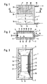
- the inspection tube 1 consists of a sight glass 2 made of transparent material, for example plexiglass or quartz glass, on the end faces 3 of which, according to FIG. 3, parallel to one another and at right angles to the sight glass 2 are side walls 4, 5.
- a sight glass 2 made of transparent material, for example plexiglass or quartz glass
- the side walls 4, 5 form with the sight glass 2 a one-piece, cross-sectionally U-shaped shape.
- the side walls 4, 5 butt against the end face 3 and are firmly connected to each other, for example by gluing using a one-component silicone adhesive.
- FIG. 3 to the left of the two side walls 4, 5 there is a wall 6 running parallel to the sight glass 2, which is connected in one piece to the side walls 4, 5 and thus forms a U-shaped profile with the side walls 4, 5 which can be produced for example in the extrusion or also in the pressing process.
- the U-shaped profile consisting of the sight glass 2 and the side walls 4, 5 is closed from its open side by a wall 6.
- the end faces 7, 8 which laterally delimit the wall 6 abut against the mutually facing inner faces 9, 10 of the side walls 4, 5 and are likewise glued to them.
- FIGS. 2 and 3 can of course also the wall (Fig. 2) or the sight glass 2 (Fig. 3) releasably and tightly connected to the side walls 4, 5 via locking and sealing elements, not shown in the drawing, so that in the event of contamination of the sight glass 2 and the wall 6 these can be cleaned from the inside after their disassembly.
- the top and bottom 11, 12 of the viewing tube 1 are sealed by a cover, but which are not shown in the drawing.
- the sight glass 2 forms with the side walls 4, 5, the wall 6 and the lids a closed chamber 13 which has an inlet pipe 14 on the underside and an outlet pipe 15 on the top.
- Exhaust pipe 15 is used to vent the chamber 13, the inlet pipe 14 is connected via a pipe to a water reservoir, not shown in the drawing, the level of which is to be checked.
- Figs. 2 and 3 are formed on the inside 16 of the sight glass 2 asperities in the form of strips 17 running parallel to one another and parallel to the longitudinal direction of the sight glass, by means of which the sight glass 2 becomes a diffusing screen in the air environment.
- the in Figs. 1 to 3 shown spreading disc has on its inside 16 strips 17 with a wavy cross section.
- display elements or markings 19 are attached in the form of lines running perpendicular to the strips 17, which, when the level indicator is properly set up and the chamber 13 is partially filled with water, parallel to Level 20 (Fig. 1) run.
- numbers 21 can also be attached to the surface 18 of the wall 6.
- the side walls 4 and 5 form the cover or the base and the cover parts (not shown) the rare surfaces of the inspection tube 1. This depends on how the display elements 19 in the form of lines form the side walls 4, 5 run.
- the display elements 19 are formed on a film 22, which is then attached to the back 23 of the wall 6 from the outside. So that the markings 19 can also be seen from the outside 24 of the lens 2, the wall 6 must of course also be transparent and provided with plane-parallel, smooth surfaces 23, 18.
- the mode of operation of the level indicator device according to the invention is as follows: If there is no water in the chamber 13 of the viewing tube 1, the light penetrating into the chamber 13 from the outside is scattered on the strips 17 in such a way that the horizontal lines 19 formed on the wall 6 as a scale-like or roof tile-shaped and hardly visible picture 25 is reproduced.
- the scales 26 are formed by the strips 17, while at the deepest points 27 (FIG. 2), ie at the transition between two strips 17 mirrored strips 28 are formed, so that the display elements are not reproduced in this area.
Landscapes
- Engineering & Computer Science (AREA)
- Food Science & Technology (AREA)
- Physics & Mathematics (AREA)
- Fluid Mechanics (AREA)
- General Physics & Mathematics (AREA)
- Cookers (AREA)
Applications Claiming Priority (2)
| Application Number | Priority Date | Filing Date | Title |
|---|---|---|---|
| DE19904011651 DE4011651A1 (de) | 1990-04-11 | 1990-04-11 | Pegelstandanzeigeeinrichtung fuer einen wasservorratsbehaelter von haushaltsgeraeten |
| DE4011651 | 1990-04-11 |
Publications (2)
| Publication Number | Publication Date |
|---|---|
| EP0451689A2 true EP0451689A2 (fr) | 1991-10-16 |
| EP0451689A3 EP0451689A3 (en) | 1991-11-27 |
Family
ID=6404175
Family Applications (1)
| Application Number | Title | Priority Date | Filing Date |
|---|---|---|---|
| EP19910105287 Withdrawn EP0451689A3 (en) | 1990-04-11 | 1991-04-03 | Level indicator for a water reservoir of a household appliance |
Country Status (2)
| Country | Link |
|---|---|
| EP (1) | EP0451689A3 (fr) |
| DE (1) | DE4011651A1 (fr) |
Cited By (5)
| Publication number | Priority date | Publication date | Assignee | Title |
|---|---|---|---|---|
| EP0625695A1 (fr) * | 1993-05-15 | 1994-11-23 | Norgren Martonair Limited | Perfectionnements aux voyants indicateurs de niveau |
| WO2002000072A1 (fr) * | 2000-06-27 | 2002-01-03 | Pulse Home Products Limited | Bouilloire eclairee |
| EP1154246A3 (fr) * | 2000-05-09 | 2003-10-15 | BSH Bosch und Siemens Hausgeräte GmbH | Indication du niveau de remplissage utilisant une source de lumière |
| EP2564737A1 (fr) * | 2011-08-30 | 2013-03-06 | BSH Bosch und Siemens Hausgeräte GmbH | Réservoir d'eau pour un appareil ménager |
| EP3395211A1 (fr) * | 2017-04-25 | 2018-10-31 | Melitta Europa GmbH & Co. KG | Broc en verre |
Families Citing this family (2)
| Publication number | Priority date | Publication date | Assignee | Title |
|---|---|---|---|---|
| DE29718374U1 (de) * | 1997-10-16 | 1998-02-19 | Rowenta-Werke GmbH, 63071 Offenbach | Getränkebereiter |
| DE10017550A1 (de) * | 2000-04-08 | 2001-10-18 | Fluidtech Gmbh | Vorrichtung zum Anzeigen und Kontrollieren von Fluidzuständen |
Family Cites Families (7)
| Publication number | Priority date | Publication date | Assignee | Title |
|---|---|---|---|---|
| US2923157A (en) * | 1956-01-03 | 1960-02-02 | Wegner Machinery Corp | Liquid level gauge |
| FR2322361A1 (fr) * | 1975-08-29 | 1977-03-25 | Massalski Casimir | Perfectionnement apporte aux indicateurs de niveau de liquide en vue d'en faciliter la lecture |
| US4021943A (en) * | 1976-02-23 | 1977-05-10 | The Hoover Company | Pressing iron water level gauge |
| SE408485B (sv) * | 1977-06-30 | 1979-06-11 | Andersson Jan | Anordning for metning eller dosering av vetskors volym |
| GB2155767A (en) * | 1984-03-24 | 1985-10-02 | Haden D H Ltd | Water heating vessel having a water level indicator |
| DE3806112A1 (de) * | 1988-02-26 | 1989-09-07 | Krups Stiftung | Geraet zum zubereiten von heissen getraenken, wie kaffee, tee od. dgl. |
| GB2215464B (en) * | 1988-03-10 | 1991-09-25 | Ziko Dr A O | Anaesthetic vaporiser |
-
1990
- 1990-04-11 DE DE19904011651 patent/DE4011651A1/de not_active Withdrawn
-
1991
- 1991-04-03 EP EP19910105287 patent/EP0451689A3/de not_active Withdrawn
Cited By (5)
| Publication number | Priority date | Publication date | Assignee | Title |
|---|---|---|---|---|
| EP0625695A1 (fr) * | 1993-05-15 | 1994-11-23 | Norgren Martonair Limited | Perfectionnements aux voyants indicateurs de niveau |
| EP1154246A3 (fr) * | 2000-05-09 | 2003-10-15 | BSH Bosch und Siemens Hausgeräte GmbH | Indication du niveau de remplissage utilisant une source de lumière |
| WO2002000072A1 (fr) * | 2000-06-27 | 2002-01-03 | Pulse Home Products Limited | Bouilloire eclairee |
| EP2564737A1 (fr) * | 2011-08-30 | 2013-03-06 | BSH Bosch und Siemens Hausgeräte GmbH | Réservoir d'eau pour un appareil ménager |
| EP3395211A1 (fr) * | 2017-04-25 | 2018-10-31 | Melitta Europa GmbH & Co. KG | Broc en verre |
Also Published As
| Publication number | Publication date |
|---|---|
| EP0451689A3 (en) | 1991-11-27 |
| DE4011651A1 (de) | 1991-10-17 |
Similar Documents
| Publication | Publication Date | Title |
|---|---|---|
| DE60124535T3 (de) | Beleuchtungsvorrichtung mit kantenbeleuchtung | |
| DE60032786T2 (de) | Waschmittelzugabevorrichtung fur eine haushaltswaschmaschine insbesondere geschirrspülmaschine | |
| DE2548728C2 (de) | Vorrichtung zur analytischen Bestimmung von Substanzen in Lösung | |
| DE4011651A1 (de) | Pegelstandanzeigeeinrichtung fuer einen wasservorratsbehaelter von haushaltsgeraeten | |
| DE60132173T2 (de) | Zählkammer mit referenz und verfahren zur herstellung einer zählkammer mit referenz | |
| DE3017551C2 (de) | Passives elektrooptisches Anzeigeelement | |
| EP1553857B1 (fr) | Appareil de nettoyage pour la tete d'un rasoir et recipient utilise pour celui-ci | |
| WO1986005879A1 (fr) | Calorimetre | |
| CH681182A5 (fr) | ||
| DE69002364T2 (de) | Optischer Druckwandler und dazugehöriges Verfahren zur Realisierung eines solchen Wandlers. | |
| EP0469608A2 (fr) | Indicateurs de niveau, notamment pour dispositifs de préparation des boissons | |
| DE202008016449U1 (de) | Behälter mit einem Raum zum Fassen einer Flüssigkeit, mit Mitteln zur Anzeige eines Pegels der Flüssigkeit | |
| DE102007060849B3 (de) | Bodendüse, insbesondere für Hartböden | |
| DE2911947C2 (de) | Flüssigkeitsstandanzeiger | |
| DE720332C (de) | Vorrichtung zum Messen der Blutfarbe | |
| DE102020209637A1 (de) | Vorrichtung zur Wasserstandsanzeige | |
| DE29822442U1 (de) | Flüssigkeitsuhr | |
| DE3413062A1 (de) | Zeitspannenmessvorrichtung | |
| DE19632896C2 (de) | Trommelgaszähler mit Schrägrohr-Pegelstandsanzeiger | |
| DE9014793U1 (de) | Vorrichtung zum Abstützen von Schmuck- oder Gebrauchsgegenständen, insbesondere von Brillen | |
| DE2049839C3 (de) | Vorrichtung zur Sichtkontrolle schlauchförmiger Textilware | |
| DE29915440U1 (de) | Dekorationsbehälter | |
| DE690619C (de) | Thermometerroehre | |
| DE29905989U1 (de) | Sprudelsäule | |
| DE802019C (de) | Fluessigkeitsstandanzeiger fuer hohe und hoechste Drucke |
Legal Events
| Date | Code | Title | Description |
|---|---|---|---|
| PUAI | Public reference made under article 153(3) epc to a published international application that has entered the european phase |
Free format text: ORIGINAL CODE: 0009012 |
|
| PUAL | Search report despatched |
Free format text: ORIGINAL CODE: 0009013 |
|
| AK | Designated contracting states |
Kind code of ref document: A2 Designated state(s): AT CH DE FR GB IT LI |
|
| AK | Designated contracting states |
Kind code of ref document: A3 Designated state(s): AT CH DE FR GB IT LI |
|
| STAA | Information on the status of an ep patent application or granted ep patent |
Free format text: STATUS: THE APPLICATION IS DEEMED TO BE WITHDRAWN |
|
| 18D | Application deemed to be withdrawn |
Effective date: 19920528 |