EP0451624B1 - Feststellbarer Reissverschlussschieber - Google Patents
Feststellbarer Reissverschlussschieber Download PDFInfo
- Publication number
- EP0451624B1 EP0451624B1 EP91104885A EP91104885A EP0451624B1 EP 0451624 B1 EP0451624 B1 EP 0451624B1 EP 91104885 A EP91104885 A EP 91104885A EP 91104885 A EP91104885 A EP 91104885A EP 0451624 B1 EP0451624 B1 EP 0451624B1
- Authority
- EP
- European Patent Office
- Prior art keywords
- pull tab
- upper wing
- resilient means
- slide fastener
- locking member
- Prior art date
- Legal status (The legal status is an assumption and is not a legal conclusion. Google has not performed a legal analysis and makes no representation as to the accuracy of the status listed.)
- Expired - Lifetime
Links
Images


Classifications
-
- A—HUMAN NECESSITIES
- A44—HABERDASHERY; JEWELLERY
- A44B—BUTTONS, PINS, BUCKLES, SLIDE FASTENERS, OR THE LIKE
- A44B19/00—Slide fasteners
- A44B19/24—Details
- A44B19/26—Sliders
-
- A—HUMAN NECESSITIES
- A44—HABERDASHERY; JEWELLERY
- A44B—BUTTONS, PINS, BUCKLES, SLIDE FASTENERS, OR THE LIKE
- A44B19/00—Slide fasteners
- A44B19/24—Details
- A44B19/26—Sliders
- A44B19/30—Sliders with means for locking in position
- A44B19/308—Sliders with means for locking in position in the form of a spring-actuated locking member actuated by the pull member
-
- A—HUMAN NECESSITIES
- A44—HABERDASHERY; JEWELLERY
- A44B—BUTTONS, PINS, BUCKLES, SLIDE FASTENERS, OR THE LIKE
- A44B19/00—Slide fasteners
- A44B19/24—Details
- A44B19/26—Sliders
- A44B19/30—Sliders with means for locking in position
-
- Y—GENERAL TAGGING OF NEW TECHNOLOGICAL DEVELOPMENTS; GENERAL TAGGING OF CROSS-SECTIONAL TECHNOLOGIES SPANNING OVER SEVERAL SECTIONS OF THE IPC; TECHNICAL SUBJECTS COVERED BY FORMER USPC CROSS-REFERENCE ART COLLECTIONS [XRACs] AND DIGESTS
- Y10—TECHNICAL SUBJECTS COVERED BY FORMER USPC
- Y10T—TECHNICAL SUBJECTS COVERED BY FORMER US CLASSIFICATION
- Y10T24/00—Buckles, buttons, clasps, etc.
- Y10T24/25—Zipper or required component thereof
- Y10T24/2561—Slider having specific configuration, construction, adaptation, or material
- Y10T24/2566—Slider having specific configuration, construction, adaptation, or material including position locking-means attached thereto
- Y10T24/257—Slider having specific configuration, construction, adaptation, or material including position locking-means attached thereto having surface engaging element shifted by reorientation of pull tab
- Y10T24/2571—Resilient or spring biased element
- Y10T24/2577—Biased by distinct spring
Definitions
- This invention relates to a lockable slider manipulated to open and close a slide fastener.
- a difficulty of this prior device is that if for some reason the tooth of the locking pawl fails to engage in the space between adjacent coupling elements as required but instead rides over the upper surfaces of the coupling elements, the locking pawl tends to somewhat press the spring so that the resilient force of the spring is not transmitted to the handle flap, leaving the latter free to wobble itself or hook on the garment or some other objects, resulting in damage to the handle flap or the hooked objects.
- the present invention seeks to provide a lockable slide fastener slider incorporating a locking means which will ensure a firm lock of the slider in any longitudinal position of the slide fastener whether it be on a coupling element, a top end stop, a bottom end stop, or an end separator and which will further ensure retention of a pull tab in flipped flat position relative to the slider body when the slider is locked.
- a lockable slide fastener slider of the invention comprises a slider body including an upper wing and a lower wing joined at one of their respective ends by a neck so as to define therebetween a guide channel for the passage of a pair of rows of coupling elements, a pull tab having a pintle and being pivotably connected through its pintle to the upper wing and having a cam means, a locking member pivotably supported on the slider body and including a locking prong movable into and away from the guide channel and a first resilient means urging the pull tab to flip down against the upper wing.
- the slider further comprises a second resilient means bearing with one end against the upper wing and being received with the other end in a space in engagement with the pull tab urging the pull tab to lie substantially flat against the upper wing in compensation for the lack of resilient forces of the first resilient means.
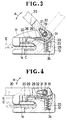
- the slider 10 comprises a slider body including an upper wing member 11 and a lower wing member 12 joined at one of their respective ends by a wedge-shaped neck 13 at a front end of the slider body so as to define therebetween a substantially Y-shaped guide channel 14 for the passage of a pair of rows of coupling elements E on respective stringer tapes T as is well known.
- the upper wing 11 has an aperture 15 communicating with the guide channel 14 for allowing the passage therethrough of a locking prong later described into and out of the channel 14 to engage and disengage the coupling elements E.
- the upper wing 11 has raised confronting side flanges 16, 16' defining therebetween a chamber 17 for receiving a pull tab later described and having a transversely aligned openings 18, 18' through which a support pin 19 is inserted as better shown in Figure 5.
- the support pin 19, which serves as a pintle of the pull tab 20, is secured in place by clamping the peripheral edges of the openings 18, 18' over the respective ends of the pin 19.
- a pull tab 20 pivotally mounted in the chamber 17 has a cross sectionally oblong transverse aperture 21 at its fulcrum end 22 for receiving the pin 19 about which the pull tab 20 is pivotally supported to rotate in the direction of the arrow A as better shown in Figure 3.
- the pull tab 20 is provided with a cam 23 projecting longitudinally from the fulcrum end 22 for purposes hereafter to be described.
- the oblong aperture 21 is convergent toward the rear end of the pull tab 20 remote from the cam 23 to provide an upwardly slanted bottom wall 21'.
- a vertically elongated well 24 for accommodating a first resilient means 25 in the form of a compression spring.
- a locking member 26 generally rectangular in shape is rockably mounted in the chamber 17 between the pull tab 20 and the upper surface of the upper wing 11, for which purpose the locking member 26 is provided with a pin 27 extending transversely from opposite sides thereof and pivotably received in U-shaped grooves 28, 28' in a pair of laterally spaced lugs 29, 29 formed on the upper surface of the upper wing 11.
- the locking member 26 is located with one end 26' overlying an upper end portion of the first resilient means 25.
- a locking prong 30 extends downwardly integrally from the opposite end of the locking member 26 and swings with pivotal movement of the locking member 26 into and out of the guide channel 14 between a first position B shown in Figure 1 in which the prong 30 engages in between adjacent coupling elements E and a second position C shown in Figure 3 in which the prong 30 is lifted away from the passage of the coupling elements E in the guide channel 14.
- a second resilient means 31 in the form of a torsion spring wrapping around or enveloping the support pin 19 and received in the oblong aperture 21 of the pull tab.
- the torsion spring 31 is disposed with one end extension 32 retained in the oblong aperture 21 and laid over the slanted bottom wall 21' thereof and with the opposite end extension 33 drawn out of the aperture 21 and borne against the inner wall of the upper wing flange 16' adjacent to the front end of the slider body, the arrangement being that the second resilient means 31 normally tends to bias the pull tab 20 counterclockwise toward the upper wing 11 as viewed in the drawing.
- the slider 10 is locked against movement by flipping the pull tab 20 counterclockwise down flat against the upper wing 11 normally with the aid of spring action of the first resilient means 25 as shown in Figure 1 in which the locking prong 30 of the locking member 26 engages in between adjacent coupling elements E in the guide channel 14.
- the slider 30 is unlocked by rotating the pull tab 20 clockwise about the pin 19, when the cam 23 abuts against the one end 26' of the locking member 26, lifting the locking prong 30 out of the guide channel 14 against the tension of the first and second resilient means 25 and 31 as shown in Figure 3.
- FIG. 6 - 9 inclusive shows a lockable slider 10 constructed in accordance with a second embodiment of the invention.
- This slider 10 is of a type somewhat similar to an automatic lock slider disclosed in U.S. Patent No. 4,391,022 to the same assignee of the present application in that it includes a locking member 26 in the form of a polygonal leaf spring which serves in effect as the first resilient means 25 as well.
- the locking member 26 has a vertically elongated one end 26' secured in place in the well 24, a generally U-shaped engaging portion 26'' and a locking prong 30 extending downwardly therefrom.
- the pull tab 20 has a pintle 40 about which it is pivotable and a first cam 41 formed centrally on the pintle 40 for engaging the U-shaped portion 26'' of the locking member 26.
- Releasing or flipping down the pull tab 20 causes the locking prong 30 to descend under the influence of the tension of the locking member 26 and engages normally in between adjascent coupling elements E thereby locking the slider 10 against unintentional movement, in which position the pull tab 20 is held flat against the upper surface of the upper wing 11 as shown in Figure 6.
- the locking prong 30 is liable to ride over and rest directly against the coupling elements E instead of entering therebetween during its descending movement with the result that the pull tab 20 is held apart from the upper wing 11 and hence tends to idle.
- This problem is overcome by the provision of a second resilient means 31 in the form of a plain leaf spring according to the second embodiment of the invention.
- the second resilient means 31 which achieves the same function and effect as discussed in connection with the first embodiment, comprises a pair of elongated leaf springs 31a, 31b accommodated in a casing 42 and laterally spaced on opposite sides of the upper wing 11 and extending in overlying relation to the locking member 26. Both ends of each of the leaf springs 31a, 31b are loosely fitted in recesses 43 formed between the casing 42 and the upper wing 11 as better shown in Figures 8 and 9, so that the leaf springs 31a, 31b can flex vertically.
- the pull tab 20 is provided with a pair of downwardly oriented second cams 44a, 44b extending from opposite ends of its pintle 40 and registering in position with the respective leaf springs 31a, 31b which normally act upon the respective cams 44a, 44b so that the pull tab 20 is urged to lie flat against the upper surface of the upper wing 11 of the slider body.
- Figures 10 - 12 inclusive shows a lockable slider 10 according to a third embodiment of the invention in which the second resilient means 31 comprises a leaf spring 31c of rectangular frame form as better shown in Figure 11.
- the leaf spring 31c is flexibly supported in a recessed surface portion 50 of the upper wing 11 and disposed in underlying relation to the locking member 26 in contrast to the second embodiment as better shown in Figure 12.
- the pull tab 20 has a first cam 51 formed centrally on a pintle 52 for engaging a U-shaped portion 26'' of the locking member 26 which is substantially similar in construction to that which appears in the second embodiment.
- the first cam 51 is normally urged downwardly by the locking member 26 in the direction of the arrow D as shown in Figure 10.
- a pair of upwardly oriented second cams 53a, 53b extend from opposite ends of the pintle 52 in overlying relation to the leaf spring 31c which urges the second cams 53a, 53b normally upwardly in the direction of the arrow F as shown in Figure 10.
Landscapes
- Slide Fasteners (AREA)
- Buckles (AREA)
Claims (5)
- Feststellbarer Reißverschlußschieber, umfassend: einen Schieberkörper mit einem Oberschild (11) und einem Unterschild (12), die an einem ihrer jeweiligen Enden durch einen Schieberkeil (13) verbunden sind, um dazwischen einen Führungskanal (14) für den Durchgang von zwei Kuppelgliederreihen(E) zu begrenzen; einen Griff (20), der einen Drehbolzen (19, 40, 52) aufweist und der durch den Drehbolzen (19, 40, 52) mit dem Oberschild (11) schwenkbar verbunden ist und der Steuerkurvenmittel (23, 41, 44a, 44b, 51, 53a, 53b) aufweist; ein Sperrglied (26), das auf dem Schieberkörper schwenkbar abgestützt ist und eine Sperrklaue (30) aufweist, die in den Führungskanal (14) hinein und aus diesem heraus bewegbar ist; und ein erstes Federmittel (25), das den Griff (20) zum Umklappen nach unten gegen den Oberschild (11) vorspannt, dadurch gekennzeichnet, daß ein zweites Federmittel (31, 31a, 31b, 31c) vorgesehen ist, dessen eines Ende am Oberschild (11) anliegt und dessen anderes Ende in einem Hohlraum (21, 43, 50) aufgenommen ist und mit dem Griff (20) in Eingriff steht, das den Griff (20) vorspannt, damit er im wesentlichen eben am Oberschild (11) anliegt, um die mangelnde Vorspannkraft des ersten Federmittels (25) auszugleichen.
- Feststellbarer Reißverschlußschieber nach Anspruch 1, dadurch gekennzeichnet, daß das zweite Federmittel (31) eine Torsionsfeder ist, die um den Drehbolzen (19) herumgewickelt und in einer länglichen Öffnung (21) des Griffs (20) aufgenommen ist.
- Feststellbarer Reißverschlußschieber nach Anspruch 1, dadurch gekennzeichnet, daß das zweite Federmittel (31) zwei Blattfedern (31a, 31b) umfaßt, die im seitlichen Abstand auf gegenüberliegenden Seiten des Oberschilds (11) angeordnet sind und das Sperrglied (26) übergreifen.
- Feststellbarer Reißverschlußschieber nach Anspruch 1, dadurch gekennzeichnet, daß das zweite Federmittel (31) eine Blattfeder (31c) von rechteckiger Form umfaßt, die das Sperrglied (26) untergreift.
- Feststellbarer Reißverschlußschieber nach Anspruch 2, dadurch gekennzeichnet, daß die längliche Öffnung zu einem hinteren Ende des Griffs (20) hin konvergiert, um eine nach oben ansteigende Bodenwand (21') zu bilden, um darauf eine Endverlängerung (32) der Torsionsfeder (31) aufzunehmen.
Priority Applications (1)
| Application Number | Priority Date | Filing Date | Title |
|---|---|---|---|
| EP95112316A EP0682890B1 (de) | 1990-04-12 | 1991-03-27 | Verriegelbarer Schieber für Reissverschlüsse |
Applications Claiming Priority (2)
| Application Number | Priority Date | Filing Date | Title |
|---|---|---|---|
| JP97077/90 | 1990-04-12 | ||
| JP2097077A JPH0761288B2 (ja) | 1990-04-12 | 1990-04-12 | スライドファスナー用停止機構付きスライダー |
Related Child Applications (2)
| Application Number | Title | Priority Date | Filing Date |
|---|---|---|---|
| EP95112316A Division EP0682890B1 (de) | 1990-04-12 | 1991-03-27 | Verriegelbarer Schieber für Reissverschlüsse |
| EP95112316.5 Division-Into | 1991-03-27 |
Publications (2)
| Publication Number | Publication Date |
|---|---|
| EP0451624A1 EP0451624A1 (de) | 1991-10-16 |
| EP0451624B1 true EP0451624B1 (de) | 1996-06-12 |
Family
ID=14182582
Family Applications (2)
| Application Number | Title | Priority Date | Filing Date |
|---|---|---|---|
| EP95112316A Expired - Lifetime EP0682890B1 (de) | 1990-04-12 | 1991-03-27 | Verriegelbarer Schieber für Reissverschlüsse |
| EP91104885A Expired - Lifetime EP0451624B1 (de) | 1990-04-12 | 1991-03-27 | Feststellbarer Reissverschlussschieber |
Family Applications Before (1)
| Application Number | Title | Priority Date | Filing Date |
|---|---|---|---|
| EP95112316A Expired - Lifetime EP0682890B1 (de) | 1990-04-12 | 1991-03-27 | Verriegelbarer Schieber für Reissverschlüsse |
Country Status (9)
| Country | Link |
|---|---|
| US (1) | US5152036A (de) |
| EP (2) | EP0682890B1 (de) |
| JP (1) | JPH0761288B2 (de) |
| KR (1) | KR930006069B1 (de) |
| CA (1) | CA2038729C (de) |
| DE (2) | DE69132558D1 (de) |
| ES (1) | ES2088441T3 (de) |
| HK (1) | HK129597A (de) |
| SG (1) | SG93749A1 (de) |
Cited By (1)
| Publication number | Priority date | Publication date | Assignee | Title |
|---|---|---|---|---|
| CN102475384A (zh) * | 2010-11-26 | 2012-05-30 | 福建浔兴拉链科技股份有限公司 | 自锁式拉链头 |
Families Citing this family (27)
| Publication number | Priority date | Publication date | Assignee | Title |
|---|---|---|---|---|
| JP3393568B2 (ja) * | 1995-08-31 | 2003-04-07 | ワイケイケイ株式会社 | 自動停止装置付スライドファスナー用スライダー |
| JP3439605B2 (ja) * | 1996-07-31 | 2003-08-25 | ワイケイケイ株式会社 | 自動停止装置付スライドファスナー用スライダー |
| JPH10127313A (ja) * | 1996-10-31 | 1998-05-19 | Ykk Corp | 自動停止装置付スライドファスナー用スライダー |
| JPH10127312A (ja) * | 1996-10-31 | 1998-05-19 | Ykk Corp | 停止装置付スライドファスナー用スライダー |
| JP3622885B2 (ja) * | 1997-12-18 | 2005-02-23 | Ykk株式会社 | 停止装置付スライダー用の開離嵌挿具 |
| US6502285B2 (en) * | 2001-03-16 | 2003-01-07 | Alice Mary Kiely | Immobilized and aligned closure systems |
| ES2729980T3 (es) | 2010-09-29 | 2019-11-07 | Ykk Corp | Cursor para cierre de cremallera |
| JP5898680B2 (ja) * | 2011-06-17 | 2016-04-06 | Ykk株式会社 | スライドファスナー用スライダー |
| EP2878221A1 (de) * | 2012-08-04 | 2015-06-03 | Kee (Guangdong) Garment Accessories Ltd | Automatischer Sperrschieber |
| CN104754979B (zh) * | 2012-10-22 | 2017-06-23 | Ykk株式会社 | 拉链用拉头 |
| CN105682501B (zh) * | 2013-10-31 | 2018-08-17 | Ykk株式会社 | 拉头 |
| GB201405748D0 (en) * | 2014-03-31 | 2014-05-14 | Coats Ltd J & P | Zip slider |
| TWI556760B (zh) * | 2014-11-12 | 2016-11-11 | 中傳企業股份有限公司 | 具有可更換式拉片的拉鍊頭組合結構 |
| CN106560107A (zh) * | 2015-12-01 | 2017-04-12 | 福建浔兴拉链科技股份有限公司 | 具有折弯直弹片的拉头 |
| JP3203767U (ja) | 2016-02-04 | 2016-04-14 | Ykk株式会社 | スライドファスナー用スライダー |
| US10064457B2 (en) * | 2016-12-20 | 2018-09-04 | Shah Technologies, LLC | Metal one piece locking slide and pull for slide fastener |
| US11432621B2 (en) | 2016-04-01 | 2022-09-06 | Shah Technologies, LLC | Metal one piece security slide and pull for slide fastener |
| US11006703B2 (en) * | 2016-04-01 | 2021-05-18 | Shah Technologies, LLC | Metal one piece slide and pull for slide fastener |
| ITUA20162338A1 (it) * | 2016-04-06 | 2017-10-06 | Ykk Europe Ltd | Gruppo di cursore per una cerniera lampo. |
| CN105795617B (zh) * | 2016-05-16 | 2018-10-09 | 理想(广东)拉链实业有限公司 | 一种弹簧拉头 |
| EP3777597B1 (de) * | 2018-04-09 | 2024-05-22 | YKK Corporation | Schieber und reissverschluss damit |
| CN111936007B (zh) * | 2018-04-09 | 2023-03-24 | Ykk株式会社 | 拉头和具备该拉头的拉链 |
| WO2019211914A1 (ja) * | 2018-05-02 | 2019-11-07 | Ykk株式会社 | スライドファスナー |
| US11559116B2 (en) | 2018-12-20 | 2023-01-24 | Ykk Corporation | Slider for slide fastener |
| CN112444197B (zh) * | 2019-08-28 | 2022-06-14 | Ykk株式会社 | 拉头检查装置 |
| CN110786595B (zh) * | 2019-11-08 | 2022-07-22 | 浙江鑫鸿拉链有限公司 | 一种衣服拉链 |
| US11241047B1 (en) * | 2021-03-03 | 2022-02-08 | Caitlin Hurst | Locking zipper and garments associated therewith |
Family Cites Families (18)
| Publication number | Priority date | Publication date | Assignee | Title |
|---|---|---|---|---|
| FR851471A (fr) * | 1938-03-10 | 1940-01-09 | Fermeture Eclair | Perfectionnements aux curseurs pour fermetures à curseurs |
| US2289585A (en) * | 1940-06-04 | 1942-07-14 | Marinsky Davis | Lock slider for separable fasteners |
| US2290834A (en) * | 1940-06-25 | 1942-07-21 | United Carr Fastener Corp | Slider |
| US2397638A (en) * | 1943-03-27 | 1946-04-02 | Pure Oil Co | Conversion of hydrocarbons |
| FR919541A (fr) * | 1944-08-21 | 1947-03-11 | Lightning Fasteners Ltd | Perfectionnements aux curseurs pour fermetures à curseur |
| US2487386A (en) * | 1945-05-01 | 1949-11-08 | Conmar Prod Corp | Automatic lock slider |
| US2646605A (en) * | 1948-09-21 | 1953-07-28 | Louis H Morin | Safety automatic lock slider |
| US2784474A (en) * | 1950-10-26 | 1957-03-12 | Louis H Morin | Reverse spring lock means for two-way separators and sliders |
| US3522050A (en) * | 1967-04-24 | 1970-07-28 | Ricoh Kk | Heat developable diazotype copy paper |
| DE1610472B1 (de) | 1967-09-20 | 1976-08-19 | Zipp Werk Gmbh | Reissverschlusschieber |
| US3837050A (en) * | 1972-12-28 | 1974-09-24 | Yoshida Kogyo Kk | Automatic locking sliders |
| JPS5426083Y2 (de) * | 1974-02-07 | 1979-08-30 | ||
| JPS5542735Y2 (de) * | 1975-12-16 | 1980-10-07 | ||
| JPS5637606Y2 (de) * | 1976-09-20 | 1981-09-03 | ||
| GB2011994A (en) * | 1978-01-05 | 1979-07-18 | Lightning Fasteners Ltd | Slider for sliding clasp fastener |
| JPS5758966Y2 (de) * | 1978-02-23 | 1982-12-16 | ||
| GB2072256B (en) | 1980-03-04 | 1983-12-21 | Yoshida Kogyo Kk | Automatic lock slider for slide fasteners |
| US4644613A (en) * | 1985-10-21 | 1987-02-24 | Talon, Inc. | Locking slider for slide fastener |
-
1990
- 1990-04-12 JP JP2097077A patent/JPH0761288B2/ja not_active Expired - Fee Related
-
1991
- 1991-03-20 CA CA002038729A patent/CA2038729C/en not_active Expired - Fee Related
- 1991-03-27 EP EP95112316A patent/EP0682890B1/de not_active Expired - Lifetime
- 1991-03-27 DE DE69132558T patent/DE69132558D1/de not_active Expired - Lifetime
- 1991-03-27 ES ES91104885T patent/ES2088441T3/es not_active Expired - Lifetime
- 1991-03-27 EP EP91104885A patent/EP0451624B1/de not_active Expired - Lifetime
- 1991-03-27 SG SG9600730A patent/SG93749A1/en unknown
- 1991-03-27 DE DE69120140T patent/DE69120140T2/de not_active Expired - Fee Related
- 1991-04-11 US US07/684,300 patent/US5152036A/en not_active Expired - Lifetime
- 1991-04-11 KR KR1019910005796A patent/KR930006069B1/ko not_active IP Right Cessation
-
1997
- 1997-06-26 HK HK129597A patent/HK129597A/xx not_active IP Right Cessation
Cited By (2)
| Publication number | Priority date | Publication date | Assignee | Title |
|---|---|---|---|---|
| CN102475384A (zh) * | 2010-11-26 | 2012-05-30 | 福建浔兴拉链科技股份有限公司 | 自锁式拉链头 |
| CN102475384B (zh) * | 2010-11-26 | 2014-08-27 | 福建浔兴拉链科技股份有限公司 | 自锁式拉链头 |
Also Published As
| Publication number | Publication date |
|---|---|
| KR930006069B1 (ko) | 1993-07-07 |
| EP0451624A1 (de) | 1991-10-16 |
| JPH03295502A (ja) | 1991-12-26 |
| HK129597A (en) | 1997-09-19 |
| ES2088441T3 (es) | 1996-08-16 |
| CA2038729C (en) | 1995-12-05 |
| CA2038729A1 (en) | 1991-10-13 |
| DE69120140D1 (de) | 1996-07-18 |
| KR910017984A (ko) | 1991-11-30 |
| EP0682890A3 (de) | 1996-05-08 |
| DE69120140T2 (de) | 1997-01-30 |
| EP0682890B1 (de) | 2001-03-14 |
| JPH0761288B2 (ja) | 1995-07-05 |
| US5152036A (en) | 1992-10-06 |
| DE69132558D1 (de) | 2001-04-19 |
| EP0682890A2 (de) | 1995-11-22 |
| SG93749A1 (en) | 2003-01-21 |
Similar Documents
| Publication | Publication Date | Title |
|---|---|---|
| EP0451624B1 (de) | Feststellbarer Reissverschlussschieber | |
| EP0402949B1 (de) | Verriegelungsvorrichtung für Reissverschluss | |
| CA1121574A (en) | Automatically locking slider for slide fastener | |
| EP0821892B1 (de) | Automatisch verriegelbarer Schieber für Reissverschlüsse | |
| CA1079934A (en) | Slider for slide fasteners | |
| EP1262115B1 (de) | Schieber für Reissverschluss mit Verriegelungsvorrichtung | |
| US5572771A (en) | Strap buckle | |
| EP0640300B1 (de) | Automatisch verriegelbarer Schieber für einen verdeckten Reissverschlüss | |
| CA1288219C (en) | Automatic locking slider for slide fasteners | |
| CA1290557C (en) | Automatic locking slider with a pair of pull tabs | |
| FI57203B (fi) | Automatiskt laosande loepare foer blixtlaos | |
| US4780938A (en) | Slide fastener slider with detachable pull tab | |
| US5694667A (en) | Automatic lock slider for slide fastener | |
| US9462853B2 (en) | Slider for slide fastener | |
| US4976014A (en) | Automatic lock slider for slide fastener | |
| CA2320006C (en) | Zipper pull of slider for slide fastener | |
| GB2359784A (en) | Ring binder mechanism held shut by inter-engaging teeth | |
| US5297321A (en) | Fastening device | |
| CA1285123C (en) | Lockable slider for slide fasteners | |
| EP0598373B1 (de) | Reissverschlussschieber | |
| EP0493787B1 (de) | Unterer teilbarer Endstop für Reissverschluss | |
| US2737699A (en) | Sliders for slide fasteners | |
| US2705356A (en) | Slide fasteners | |
| JPH0932815A (ja) | ロック機構 | |
| GB2180593A (en) | Automatic locking slider for slide fasteners |
Legal Events
| Date | Code | Title | Description |
|---|---|---|---|
| PUAI | Public reference made under article 153(3) epc to a published international application that has entered the european phase |
Free format text: ORIGINAL CODE: 0009012 |
|
| AK | Designated contracting states |
Kind code of ref document: A1 Designated state(s): DE ES FR GB IT SE |
|
| 17P | Request for examination filed |
Effective date: 19920116 |
|
| 17Q | First examination report despatched |
Effective date: 19930413 |
|
| RAP1 | Party data changed (applicant data changed or rights of an application transferred) |
Owner name: YKK CORPORATION |
|
| GRAH | Despatch of communication of intention to grant a patent |
Free format text: ORIGINAL CODE: EPIDOS IGRA |
|
| GRAH | Despatch of communication of intention to grant a patent |
Free format text: ORIGINAL CODE: EPIDOS IGRA |
|
| GRAA | (expected) grant |
Free format text: ORIGINAL CODE: 0009210 |
|
| AK | Designated contracting states |
Kind code of ref document: B1 Designated state(s): DE ES FR GB IT SE |
|
| XX | Miscellaneous (additional remarks) |
Free format text: TEILANMELDUNG 95112316.5 EINGEREICHT AM 04/08/95. |
|
| ET | Fr: translation filed | ||
| REG | Reference to a national code |
Ref country code: ES Ref legal event code: BA2A Ref document number: 2088441 Country of ref document: ES Kind code of ref document: T3 |
|
| ITF | It: translation for a ep patent filed |
Owner name: JACOBACCI & PERANI S.P.A. |
|
| REF | Corresponds to: |
Ref document number: 69120140 Country of ref document: DE Date of ref document: 19960718 |
|
| REG | Reference to a national code |
Ref country code: ES Ref legal event code: FG2A Ref document number: 2088441 Country of ref document: ES Kind code of ref document: T3 |
|
| PGFP | Annual fee paid to national office [announced via postgrant information from national office to epo] |
Ref country code: SE Payment date: 19961206 Year of fee payment: 7 |
|
| PGFP | Annual fee paid to national office [announced via postgrant information from national office to epo] |
Ref country code: ES Payment date: 19970303 Year of fee payment: 7 |
|
| PGFP | Annual fee paid to national office [announced via postgrant information from national office to epo] |
Ref country code: GB Payment date: 19970318 Year of fee payment: 7 |
|
| PLBE | No opposition filed within time limit |
Free format text: ORIGINAL CODE: 0009261 |
|
| STAA | Information on the status of an ep patent application or granted ep patent |
Free format text: STATUS: NO OPPOSITION FILED WITHIN TIME LIMIT |
|
| PGFP | Annual fee paid to national office [announced via postgrant information from national office to epo] |
Ref country code: DE Payment date: 19970430 Year of fee payment: 7 |
|
| 26N | No opposition filed | ||
| PG25 | Lapsed in a contracting state [announced via postgrant information from national office to epo] |
Ref country code: GB Free format text: LAPSE BECAUSE OF NON-PAYMENT OF DUE FEES Effective date: 19980327 |
|
| PG25 | Lapsed in a contracting state [announced via postgrant information from national office to epo] |
Ref country code: SE Free format text: LAPSE BECAUSE OF NON-PAYMENT OF DUE FEES Effective date: 19980328 Ref country code: ES Free format text: LAPSE BECAUSE OF EXPIRATION OF PROTECTION Effective date: 19980328 |
|
| GBPC | Gb: european patent ceased through non-payment of renewal fee |
Effective date: 19980327 |
|
| PG25 | Lapsed in a contracting state [announced via postgrant information from national office to epo] |
Ref country code: DE Free format text: LAPSE BECAUSE OF NON-PAYMENT OF DUE FEES Effective date: 19981201 |
|
| EUG | Se: european patent has lapsed |
Ref document number: 91104885.8 |
|
| REG | Reference to a national code |
Ref country code: ES Ref legal event code: FD2A Effective date: 20000201 |
|
| PG25 | Lapsed in a contracting state [announced via postgrant information from national office to epo] |
Ref country code: IT Free format text: LAPSE BECAUSE OF NON-PAYMENT OF DUE FEES Effective date: 20050327 |
|
| PGFP | Annual fee paid to national office [announced via postgrant information from national office to epo] |
Ref country code: FR Payment date: 20100324 Year of fee payment: 20 |